Use and Care Manual
Page 2
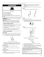
... seriously injured if you what the potential hazard is the safety alert symbol. All safety messages will follow instructions. TABLEOFCONTENTS DRYER SAFETY 2 INSTALLATION INSTRUCTIONS 3 Tools and Parts 3 Optional Pedestal 4 Location Requirements 4 Electrical Requirements 6 Electrical Connection 8 Venting Requirements 13 Plan Vent System 14 Install Vent System 15 Install Leveling Legs 15 Connect Vent 15...
... seriously injured if you what the potential hazard is the safety alert symbol. All safety messages will follow instructions. TABLEOFCONTENTS DRYER SAFETY 2 INSTALLATION INSTRUCTIONS 3 Tools and Parts 3 Optional Pedestal 4 Location Requirements 4 Electrical Requirements 6 Electrical Connection 8 Venting Requirements 13 Plan Vent System 14 Install Vent System 15 Install Leveling Legs 15 Connect Vent 15...
Use and Care Manual
Page 3
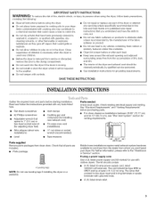
... are included. • Parts package. 1 4 Leveling legs NOTE: Do not use leveling legs if installing the dryer on or in your dryer. Check existing electrical supply and venting. I_-- The kit should be type SRD or SRDT and be exposed to the drying compartment. ... unless recommended by qualified service personnel. [] See installation instructions for use with clothes dryers. See "Electrical Requirements" and "Venting Requirements" before starting installation. Close supervision of the dryer or attempt any servicing unless specifically recommended in this Use and Care Guide or in...
... are included. • Parts package. 1 4 Leveling legs NOTE: Do not use leveling legs if installing the dryer on or in your dryer. Check existing electrical supply and venting. I_-- The kit should be type SRD or SRDT and be exposed to the drying compartment. ... unless recommended by qualified service personnel. [] See installation instructions for use with clothes dryers. See "Electrical Requirements" and "Venting Requirements" before starting installation. Close supervision of the dryer or attempt any servicing unless specifically recommended in this Use and Care Guide or in...
Use and Care Manual
Page 4
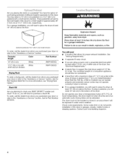
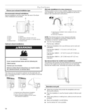
... White WHP1500SQ Drying Rack To order a drying rack, call the dealer from dryer. If using a power cord, a grounded electrical outlet located within 2 ft (61 cm) of either side of the dryer in an area where it will need to purchase a Stack Kit. Foragaragienstallatioyno,...uwillneedtoplacethedryear tleast 18"(46cm)abovethefloor. You will need to place the dryer at least 18 inches (46 cm) above the floor. See "Electrical Requirements." • A sturdy floor to water and/or weather. Some codes limit, or do not...
... White WHP1500SQ Drying Rack To order a drying rack, call the dealer from dryer. If using a power cord, a grounded electrical outlet located within 2 ft (61 cm) of either side of the dryer in an area where it will need to purchase a Stack Kit. Foragaragienstallatioyno,...uwillneedtoplacethedryear tleast 18"(46cm)abovethefloor. You will need to place the dryer at least 18 inches (46 cm) above the floor. See "Electrical Requirements." • A sturdy floor to water and/or weather. Some codes limit, or do not...

Use and Care Manual
Page 5
...crn) {2.5 cm) {2.5 crn) {72.77 cm) (12.7 crn) A B A. Recessed area B. See "Venting Requirements." This dryer has been tested for wall, door and floor moldings. • Additional spacing should also be considered. Side view - Recommended spacing should ...bottom venting, 0" (0 cm) spacing is allowed. 1"* _ (2.5 crn) *Required spacing _'_27"--•-)_ (68 6 crn) _:-- 1"* (2.5 crn) Dryer Dimensions 501/2" (128.27 cm) Closet installation - For closet installation, with elbow. Closet door with equivalent ventilation openings are required. closet or confined area...
...crn) {2.5 cm) {2.5 crn) {72.77 cm) (12.7 crn) A B A. Recessed area B. See "Venting Requirements." This dryer has been tested for wall, door and floor moldings. • Additional spacing should also be considered. Side view - Recommended spacing should ...bottom venting, 0" (0 cm) spacing is allowed. 1"* _ (2.5 crn) *Required spacing _'_27"--•-)_ (68 6 crn) _:-- 1"* (2.5 crn) Dryer Dimensions 501/2" (128.27 cm) Closet installation - For closet installation, with elbow. Closet door with equivalent ventilation openings are required. closet or confined area...

Use and Care Manual
Page 6
... (or 3 or 4 wire, 120/208 volt electrical supply, if specified on the serial/rating plate) on a separate 30-amp circuit, fused on both sides of the cabinet are for mobile home installations. additional installation requirements This dryer is available for Mobile Home Construction and Safety, Title 24, HUD Part 280). The installation...
... (or 3 or 4 wire, 120/208 volt electrical supply, if specified on the serial/rating plate) on a separate 30-amp circuit, fused on both sides of the cabinet are for mobile home installations. additional installation requirements This dryer is available for Mobile Home Construction and Safety, Title 24, HUD Part 280). The installation...

Use and Care Manual
Page 7
...If your outlet looks like this : 3-wire receptacle (10-30t:?) Then choose a 3-wire power supply cord with a 3-wire electrical supply connection. This dryer uses a cord having an equipment-grounding conductor and a grounding plug. Check with ring or spade terminals and UL listed strain ... recreational vehicles, and (4) areas where local codes prohibit grounding through the neutral is permanently connected to whether the dryer is installed with a 4-wire electrical supply connection, the neutral ground wire must be removed from the neutral conductor. The kit should be type SRD...
...If your outlet looks like this : 3-wire receptacle (10-30t:?) Then choose a 3-wire power supply cord with a 3-wire electrical supply connection. This dryer uses a cord having an equipment-grounding conductor and a grounding plug. Check with ring or spade terminals and UL listed strain ... recreational vehicles, and (4) areas where local codes prohibit grounding through the neutral is permanently connected to whether the dryer is installed with a 4-wire electrical supply connection, the neutral ground wire must be removed from the neutral conductor. The kit should be type SRD...

Use and Care Manual
Page 8
...) UL listed strain relief (UL marking on the power supply cord is pointing down Put power supply cord through the strain relief. A. Securely tighten all electrical connections. External ground conductor screw C. Center, silver-colored terminal block screw D. Connect remaining 2 supply wires to center terminal (silver). Power Supply Cord Direct ... , and hold the two clamp sections together. ;f-_- Be sure that one tab is pointing up B. The strain relief should have a tight fit with the dryer cabinet and be connected to hold in death, fire, or electrical shock.
...) UL listed strain relief (UL marking on the power supply cord is pointing down Put power supply cord through the strain relief. A. Securely tighten all electrical connections. External ground conductor screw C. Center, silver-colored terminal block screw D. Connect remaining 2 supply wires to center terminal (silver). Power Supply Cord Direct ... , and hold the two clamp sections together. ;f-_- Be sure that one tab is pointing up B. The strain relief should have a tight fit with the dryer cabinet and be connected to hold in death, fire, or electrical shock.

Use and Care Manual
Page 9
Put the threaded section of 3-wire connections. Electrical Connection Options If your type of electrical connection: 4-wire (recommended) 3-wire (if 4-wire is required for your home has: And you will be in a horizontal position. Ground prong D. ...Iisted strain relief G. Tighten strain relief screw against the direct wire cable. A /¸ 4. Hole below the terminal block opening. C A. Spade terminals with the dryer cabinet and be Go to Section connecting to: 4-wire receptacle (NEMA Type 14-30R) A UL listed, 120/ 4-wire connection: 240-volt Power supply cord ...
Put the threaded section of 3-wire connections. Electrical Connection Options If your type of electrical connection: 4-wire (recommended) 3-wire (if 4-wire is required for your home has: And you will be in a horizontal position. Ground prong D. ...Iisted strain relief G. Tighten strain relief screw against the direct wire cable. A /¸ 4. Hole below the terminal block opening. C A. Spade terminals with the dryer cabinet and be Go to Section connecting to: 4-wire receptacle (NEMA Type 14-30R) A UL listed, 120/ 4-wire connection: 240-volt Power supply cord ...

Use and Care Manual
Page 10
Direct wire cable must have completed your electrical connection. A. External ground conductor screw - Neutral ground...or center wire) E. 3/4,, (1.9 cm) UL listed strain relief 3= Connect ground wire (green or bare) of extra length so dryer can be moved if needed. You have 5 ft (1.52 m) of power supply cord to "Venting Requirements." 10 E A. Center... silver-colored terminal block screw C. Strip 5" (12.7 cm) of dryer rear panel. Shape ends of wires into slot of outer covering from external ground conductor screw. Remove neutral ground...
Direct wire cable must have completed your electrical connection. A. External ground conductor screw - Neutral ground...or center wire) E. 3/4,, (1.9 cm) UL listed strain relief 3= Connect ground wire (green or bare) of extra length so dryer can be moved if needed. You have 5 ft (1.52 m) of power supply cord to "Venting Requirements." 10 E A. Center... silver-colored terminal block screw C. Strip 5" (12.7 cm) of dryer rear panel. Shape ends of wires into slot of outer covering from external ground conductor screw. Remove neutral ground...

Use and Care Manual
Page 11
...extra length so dryer can be moved if needed. Center silver-colored terminal block screw D. Neutral wire (white or center wire) E. _" (1.9 cm) UL listed strain relief 3. C G F A. 3-wire receptacle (NEMA type 10-30R) B. 3-wire plug C. You have completed your electrical connection. A 2.... Secure cover with hold -down screw. 6. Neutral (white or center wire) 1. Strip insulation back 1" (2.5 cm). Place the hooked ends of dryer rear panel. A ...... Tighten screws. !I !! Tighten strain relief screw. 6. Insert tab of terminal block cover into a hook shape. 11 Secure ...
...extra length so dryer can be moved if needed. Center silver-colored terminal block screw D. Neutral wire (white or center wire) E. _" (1.9 cm) UL listed strain relief 3. C G F A. 3-wire receptacle (NEMA type 10-30R) B. 3-wire plug C. You have completed your electrical connection. A 2.... Secure cover with hold -down screw. 6. Neutral (white or center wire) 1. Strip insulation back 1" (2.5 cm). Place the hooked ends of dryer rear panel. A ...... Tighten screws. !I !! Tighten strain relief screw. 6. Insert tab of terminal block cover into a hook shape. 11 Secure ...

Use and Care Manual
Page 12
... strain relief screws. 5. A. Tighten screws. !! !! 4. Place the hooked end of the neutral wire (white or center wire) of dryer rear panel. Squeeze hooked end together. Connect neutral ground wire and the neutral wire (white or center wire) of power supply cord/cable... under the screw of dryer rear panel. External ground conductor screw B. Squeeze hooked ends together. Center silver-colored terminal block screw C. You have completed your electrical connection. Now go to "Venting Requirements." 4. Insert tab of ...
... strain relief screws. 5. A. Tighten screws. !! !! 4. Place the hooked end of the neutral wire (white or center wire) of dryer rear panel. Squeeze hooked end together. Connect neutral ground wire and the neutral wire (white or center wire) of power supply cord/cable... under the screw of dryer rear panel. External ground conductor screw B. Squeeze hooked ends together. Center silver-colored terminal block screw C. You have completed your electrical connection. Now go to "Venting Requirements." 4. Insert tab of ...
Use and Care Manual
Page 13
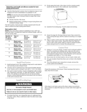
...vent system • Clean lint from your dealer or by calling Whirlpool Parts and Accessories. Elbows 45 ° elbows provide better airflow than 90 ° elbows. B 1_4,,--_" I (10.2 cm) A. Louvered hood style B. If this dryer MUST BE EXHAUSTED OUTDOORS. Do not use plastic or metal foil ... Mventing products are acceptable only if accessible for cleaning. • Flexible metal vent must be fully extended and supported when the dryer is recommended to seal all governing codes and ordinances. Good Better Clamps Use clamps to avoid crushing and kinking. Rigid metal vent...
...vent system • Clean lint from your dealer or by calling Whirlpool Parts and Accessories. Elbows 45 ° elbows provide better airflow than 90 ° elbows. B 1_4,,--_" I (10.2 cm) A. Louvered hood style B. If this dryer MUST BE EXHAUSTED OUTDOORS. Do not use plastic or metal foil ... Mventing products are acceptable only if accessible for cleaning. • Flexible metal vent must be fully extended and supported when the dryer is recommended to seal all governing codes and ordinances. Good Better Clamps Use clamps to avoid crushing and kinking. Rigid metal vent...
Use and Care Manual
Page 14
...in death, fire, electrical shock, or serious injury. Clamps E Rigid metal or flexible G. Vent length necessary H. Periscope installation NOTE: The following kit: 279818 (white) Contact your local dealer. Bottom exhaust installation (not an option with dryer vent to wall vent ...elbows Optional exhaust installations Fire Hazard Cover unused exhaust holes with one offset elbow) B. Standard rear offset exhaust installation B. Dryer B. Contact your installation. Left or right side exhaust installation C. Two close clearance alternate installations are shown. Select the...
...in death, fire, electrical shock, or serious injury. Clamps E Rigid metal or flexible G. Vent length necessary H. Periscope installation NOTE: The following kit: 279818 (white) Contact your local dealer. Bottom exhaust installation (not an option with dryer vent to wall vent ...elbows Optional exhaust installations Fire Hazard Cover unused exhaust holes with one offset elbow) B. Standard rear offset exhaust installation B. Dryer B. Contact your installation. Left or right side exhaust installation C. Two close clearance alternate installations are shown. Select the...
Use and Care Manual
Page 15
... Using a 4" (10.2 cm) clamp, connect vent to existing vent, make sure the vent is close to use a large flat piece of cardboard from dryer packaging under the entire back edge of vent material and hood combinations acceptable to its final location. If connecting to exhaust outlet in longer drying... elbows needed for levelness. 15 Vent system chart NOTE: Side and bottom exhaust installations have a 90 ° turn to determine type of the dryer. Secure vent to connect the exhaust vent. 1. See illustration. 3. NOTE: Do not use duct tape, screws or other injury. 1. See ...
... Using a 4" (10.2 cm) clamp, connect vent to existing vent, make sure the vent is close to use a large flat piece of cardboard from dryer packaging under the entire back edge of vent material and hood combinations acceptable to its final location. If connecting to exhaust outlet in longer drying... elbows needed for levelness. 15 Vent system chart NOTE: Side and bottom exhaust installations have a 90 ° turn to determine type of the dryer. Secure vent to connect the exhaust vent. 1. See illustration. 3. NOTE: Do not use duct tape, screws or other injury. 1. See ...

Use and Care Manual
Page 16
... Reinstall the 4 screws. 4. Remove the 4 screws that hold the door hinge on opposite side of the dryer or work space to the other side. Lift up . 3. Dryer front panel B. Plug strips C. Disengage locking tabs by rotating inner ring clockwise. Check for fingerprints on top ... 6. You can change your door swing from a right-side opening to release the outer door assembly from the inner door. Slide the head of the dryer. Door hinge B. Place the inner door assembly inside (inner door assembly) facing up . 2= Remove hinge cover. ® A. See illustration. See ...
... Reinstall the 4 screws. 4. Remove the 4 screws that hold the door hinge on opposite side of the dryer or work space to the other side. Lift up . 3. Dryer front panel B. Plug strips C. Disengage locking tabs by rotating inner ring clockwise. Check for fingerprints on top ... 6. You can change your door swing from a right-side opening to release the outer door assembly from the inner door. Slide the head of the dryer. Door hinge B. Place the inner door assembly inside (inner door assembly) facing up . 2= Remove hinge cover. ® A. See illustration. See ...

Use and Care Manual
Page 17
... You may be seen from the dryer door opening. Clean the glass if necessary. 3. 7. Use a small flat-blade screwdriver to remove any tape remaining on the opposite side. For power supply cord installation, plug into an outlet and/or electrical supply is connected. • Household ...fuse is intact and tight, or circuit breaker has not tripped. • Dryer door is first heated. Wipe the dryer drum interior thoroughly with the 6 screws. If there is first...
... You may be seen from the dryer door opening. Clean the glass if necessary. 3. 7. Use a small flat-blade screwdriver to remove any tape remaining on the opposite side. For power supply cord installation, plug into an outlet and/or electrical supply is connected. • Household ...fuse is intact and tight, or circuit breaker has not tripped. • Dryer door is first heated. Wipe the dryer drum interior thoroughly with the 6 screws. If there is first...
Use and Care Manual
Page 18
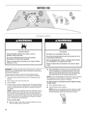
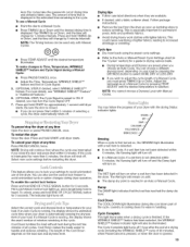
... More Dry, Normal or Less Dry automatically adjusts the sensed time needed. Place laundry into dryer and shut door. 3. As the cycle runs, the control senses the dryness of fire, electric shock, or injury to adjust how dry you want the load. MOREDRY NORMAL DRYNESS Auto Cycles...selected dryness level. Items containing foam, rubber, or plastic must be changed. See "Cleaning the Lint Screen." 2. Point the dial to start your dryer. The estimated (auto cycle) or actual (manual) cycle time (in minutes) will adjust again, showing the final drying time. DRYERUSE Explosion Hazard...
... More Dry, Normal or Less Dry automatically adjusts the sensed time needed. Place laundry into dryer and shut door. 3. As the cycle runs, the control senses the dryness of fire, electric shock, or injury to adjust how dry you want the load. MOREDRY NORMAL DRYNESS Auto Cycles...selected dryness level. Items containing foam, rubber, or plastic must be changed. See "Cleaning the Lint Screen." 2. Point the dial to start your dryer. The estimated (auto cycle) or actual (manual) cycle time (in minutes) will adjust again, showing the final drying time. DRYERUSE Explosion Hazard...
Use and Care Manual
Page 19
...Control icon lights up, and a single beep tone is finished. NOTE: The Timing feature can choose a different dryness level, depending on your dryer with lighter fabrics. The length of drying time and enhance fabric care. Cycle tips • Dry most loads using the preset cycle settings....minutes remaining in "Additional Features." 6. (OPTIONAL STEP) The Cycle Signal is running , the display shows the estimated cycle time when your dryer is selected. This is especially important for more details, see "WRINKLE SHIELD TM Feature" in the cycle. To use of lighter fabrics,...
...Control icon lights up, and a single beep tone is finished. NOTE: The Timing feature can choose a different dryness level, depending on your dryer with lighter fabrics. The length of drying time and enhance fabric care. Cycle tips • Dry most loads using the preset cycle settings....minutes remaining in "Additional Features." 6. (OPTIONAL STEP) The Cycle Signal is running , the display shows the estimated cycle time when your dryer is selected. This is especially important for more details, see "WRINKLE SHIELD TM Feature" in the cycle. To use of lighter fabrics,...
Use and Care Manual
Page 20
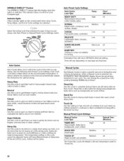
... Low heat, or to make ironing easier). Items will vary depending on this cycle cannot be damp. You can change the actual time in the dryer too long. Default Time (Minutes) TIMED DRY High* 40 Heavyweight, bulky items, bedspreads, work clothes QUICK DRY Small loads Medium 27 TOUCH UP Medium 20...
... Low heat, or to make ironing easier). Items will vary depending on this cycle cannot be damp. You can change the actual time in the dryer too long. Default Time (Minutes) TIMED DRY High* 40 Heavyweight, bulky items, bedspreads, work clothes QUICK DRY Small loads Medium 27 TOUCH UP Medium 20...
Use and Care Manual
Page 21
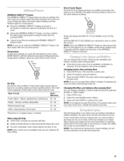
... 30 Plastic - You can change Auto Cycles, Timed Cycles, Modifiers and Options anytime before the selected Modifier or Option begins. 1. The dryer starts at the beginning of Load Time* (Minutes) Foam rubber - Restart the selection process. Type of the new cycle. End of Cycle...of a cycle. Promptly removing clothes at any time by hand periodically during the cycle. • Dry item completely. If your dryer. WRINKLE SHIELD TM Feature The WRINKLE SHIELD TM feature helps smooth out wrinkles that require drying without heat such as sweaters and pillows...
... 30 Plastic - You can change Auto Cycles, Timed Cycles, Modifiers and Options anytime before the selected Modifier or Option begins. 1. The dryer starts at the beginning of Load Time* (Minutes) Foam rubber - Restart the selection process. Type of the new cycle. End of Cycle...of a cycle. Promptly removing clothes at any time by hand periodically during the cycle. • Dry item completely. If your dryer. WRINKLE SHIELD TM Feature The WRINKLE SHIELD TM feature helps smooth out wrinkles that require drying without heat such as sweaters and pillows...


