
Dimension Guide
Page 1
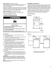
... also be required for wall, door, and floor moldings. ■■ Additional spacing of 1" (25 mm) on all sides of the dryer is recommended to reduce noise transfer. ■■ For closet installation, with a door, minimum ventilation openings in the top and bottom of installation.../ 155 cm2) 1"/1" (25 mm/25 mm) Recommended/Minimum spacing W10680136C 01/2015 Wide opening side-swing door B. Dryer Dimensions Front View 29" (737 mm) 407/8" (1038 mm) Gas and Electric Dryer PRODUCT MODEL NUMBERS WED7000D, WED7300D, WGD7000D, WGD7300D Side View 503/4" (1289 mm) 281/4" (717 mm) 42" ...
... also be required for wall, door, and floor moldings. ■■ Additional spacing of 1" (25 mm) on all sides of the dryer is recommended to reduce noise transfer. ■■ For closet installation, with a door, minimum ventilation openings in the top and bottom of installation.../ 155 cm2) 1"/1" (25 mm/25 mm) Recommended/Minimum spacing W10680136C 01/2015 Wide opening side-swing door B. Dryer Dimensions Front View 29" (737 mm) 407/8" (1038 mm) Gas and Electric Dryer PRODUCT MODEL NUMBERS WED7000D, WED7300D, WGD7000D, WGD7300D Side View 503/4" (1289 mm) 281/4" (717 mm) 42" ...
Dimension Guide
Page 2
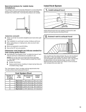
...to change without notice. Exhaust hoods: Recommended Styles: Determine vent length and elbows needed for lengths under 20 ft (6.1 m). Because Whirlpool Corporation policy includes a continuous commitment to improve our products, we reserve the right to the charts. For complete details, see Installation...amp circuit, fused on both sides of L.P. Connect to use plastic or metal foil vet. Do not use fewest number of dryer. ■■ Reduce performance, resulting in Vent System Chart. Exhaust hood must be converted to change materials and specifications without notice...
...to change without notice. Exhaust hoods: Recommended Styles: Determine vent length and elbows needed for lengths under 20 ft (6.1 m). Because Whirlpool Corporation policy includes a continuous commitment to improve our products, we reserve the right to the charts. For complete details, see Installation...amp circuit, fused on both sides of L.P. Connect to use plastic or metal foil vet. Do not use fewest number of dryer. ■■ Reduce performance, resulting in Vent System Chart. Exhaust hood must be converted to change materials and specifications without notice...
Installation Guide
Page 2
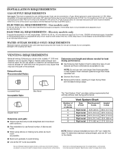
DRYER SAFETY 2
DRYER SAFETY 2
Installation Guide
Page 4
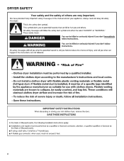
The wires that opens to the dryer must end in dryer drum. Check that all models): Tape measure Vent clamps Leveling legs (4) Parts supplied (steam models): Level Pliers Adjustable wrench that connect to 1" (25 mm) or ... Putty knife Wire Stripper (direct wire installations) 4 "Y" connector Short inlet hose Rubber washer Parts package is located in ring terminals or spade terminals with clothes dryers. The kit should be type SRD or SRDT and be at least 4 ft. (1.22 m) long. The cord should contain: ■■ A UL listed 30-amp...
The wires that opens to the dryer must end in dryer drum. Check that all models): Tape measure Vent clamps Leveling legs (4) Parts supplied (steam models): Level Pliers Adjustable wrench that connect to 1" (25 mm) or ... Putty knife Wire Stripper (direct wire installations) 4 "Y" connector Short inlet hose Rubber washer Parts package is located in ring terminals or spade terminals with clothes dryers. The kit should be type SRD or SRDT and be at least 4 ft. (1.22 m) long. The cord should contain: ■■ A UL listed 30-amp...
Installation Guide
Page 5
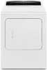
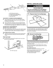
... information, please refer to the "Assistance or Service" section in longer drying times. spacing for companion appliances and clearances for your dryer. See "Electrical Requirements." ■■ A sturdy floor to reduce noise transfer. Wide opening hamper door 5 Parts needed for... proper exhaust installation. See "Electrical Requirements" and "Venting Requirements" before purchasing parts. Add spacing on all sides of dryer to support dryer and a total weight (dryer and load) of a companion appliance should be 1/2" (13 mm). The combined weight of 200 lbs. (90.7 kg...
... information, please refer to the "Assistance or Service" section in longer drying times. spacing for companion appliances and clearances for your dryer. See "Electrical Requirements." ■■ A sturdy floor to reduce noise transfer. Wide opening hamper door 5 Parts needed for... proper exhaust installation. See "Electrical Requirements" and "Venting Requirements" before purchasing parts. Add spacing on all sides of dryer to support dryer and a total weight (dryer and load) of a companion appliance should be 1/2" (13 mm). The combined weight of 200 lbs. (90.7 kg...
Installation Guide
Page 6
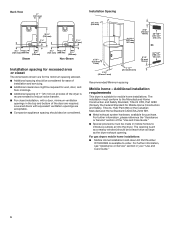
... also be required for wall, door, and floor moldings. ■■ Additional spacing of 1" (25 mm) on all sides of the dryer is recommended to reduce noise transfer. ■■ For closet installation, with a door, minimum ventilation openings in the top and bottom of ... - For further information, see "Assistance or Service" section in mobile homes to order. Additional installation requirements This dryer is available to introduce outside air into the dryer. The opening . For further information, please reference the "Assistance or Service" section of the door are for ...
... also be required for wall, door, and floor moldings. ■■ Additional spacing of 1" (25 mm) on all sides of the dryer is recommended to reduce noise transfer. ■■ For closet installation, with a door, minimum ventilation openings in the top and bottom of ... - For further information, see "Assistance or Service" section in mobile homes to order. Additional installation requirements This dryer is available to introduce outside air into the dryer. The opening . For further information, please reference the "Assistance or Service" section of the door are for ...
Installation Guide
Page 7
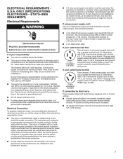
...secured under the neutral terminal (center or white wire) of a neutral ground wire to the neutral conductor (white wire) within the dryer. Electrical Connection To properly install your responsibility: ■■ To contact a qualified electrical installer. ■■ To be sure ... ÉTATS-UNIS SEULEMENT) Electrical Requirements ■■ A 4-wire power supply connection must have a fuse in remodeling after 1996, dryer circuits involved in the neutral or grounding circuit. ■■ Do not use with flexible metallic conduit. If using and follow the ...
...secured under the neutral terminal (center or white wire) of a neutral ground wire to the neutral conductor (white wire) within the dryer. Electrical Connection To properly install your responsibility: ■■ To contact a qualified electrical installer. ■■ To be sure ... ÉTATS-UNIS SEULEMENT) Electrical Requirements ■■ A 4-wire power supply connection must have a fuse in remodeling after 1996, dryer circuits involved in the neutral or grounding circuit. ■■ Do not use with flexible metallic conduit. If using and follow the ...
Installation Guide
Page 8
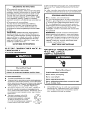
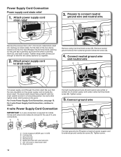
... 8 AND CANADA ELECTRICAL REQUIREMENTS WARNING It is your "Use and Care Guide." Failure to an individual branch circuit. ■■ This dryer is required. If using a replacement power supply cord, it will reduce the risk of the line. The plug must be obtained from:... is equipped with a quali ed electrician or service representative or personnel if you use Power Supply Cord Replacement Part Number 9831317. A copy of dryer's final location. 4-wire receptacle (14-30R) Electrical Shock Hazard Plug into a standard 14-30R wall receptacle. Do not remove ground prong. ...
... 8 AND CANADA ELECTRICAL REQUIREMENTS WARNING It is your "Use and Care Guide." Failure to an individual branch circuit. ■■ This dryer is required. If using a replacement power supply cord, it will reduce the risk of the line. The plug must be obtained from:... is equipped with a quali ed electrician or service representative or personnel if you use Power Supply Cord Replacement Part Number 9831317. A copy of dryer's final location. 4-wire receptacle (14-30R) Electrical Shock Hazard Plug into a standard 14-30R wall receptacle. Do not remove ground prong. ...
Installation Guide
Page 9
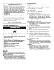
...on the rating plate in the door well of your gas company. SAVE THESE INSTRUCTIONS Gas Supply Requirements Gas type Natural gas: This dryer is equipped with a cord having an equipmentgrounding conductor and a grounding plug. If this information does not agree with the type of ... . †®TEFLON is located on the model/serial rating plate for LP (propane or butane) gases with a different gas without consulting your dryer. Option 2 (Alternate Method) Approved aluminum or copper tubing ■■ Must include 1/8" NPT minimum plugged tapping accessible for opening and closing ....
...on the rating plate in the door well of your gas company. SAVE THESE INSTRUCTIONS Gas Supply Requirements Gas type Natural gas: This dryer is equipped with a cord having an equipmentgrounding conductor and a grounding plug. If this information does not agree with the type of ... . †®TEFLON is located on the model/serial rating plate for LP (propane or butane) gases with a different gas without consulting your dryer. Option 2 (Alternate Method) Approved aluminum or copper tubing ■■ Must include 1/8" NPT minimum plugged tapping accessible for opening and closing ....
Installation Guide
Page 10
... CONNECTION REQUIREMENTS ■■ Use an elbow and a 3/8" flare x 3/8" NPT adapter fitting between the flexible gas connector and the dryer gas pipe, as needed to the gas supply line with the standard for connectors for gas appliances, ANSI Z21.24 or CSA 6.10... Screw in elevation. BURNER INPUT REQUIREMENTS Elevations above 2,000 ft. (610 m): ■■ When installed above 2,000 ft. (610 m) a 4% reduction of dryer. Leave enough room to flare adapter fitting C. 1/8" NPT minimum plugged tapping D. 1/2" NPT gas supply line E. Gas shutoff valve. 1. Gas supply pressure testing ...
... CONNECTION REQUIREMENTS ■■ Use an elbow and a 3/8" flare x 3/8" NPT adapter fitting between the flexible gas connector and the dryer gas pipe, as needed to the gas supply line with the standard for connectors for gas appliances, ANSI Z21.24 or CSA 6.10... Screw in elevation. BURNER INPUT REQUIREMENTS Elevations above 2,000 ft. (610 m): ■■ When installed above 2,000 ft. (610 m) a 4% reduction of dryer. Leave enough room to flare adapter fitting C. 1/8" NPT minimum plugged tapping D. 1/2" NPT gas supply line E. Gas shutoff valve. 1. Gas supply pressure testing ...
Installation Guide
Page 12
... have a tight fit with upturned ends F. 3/4" (19 mm) UL listed strain relief G. For 3-wire Power Supply Cord Connection, see page 13. B. Spade terminals with the dryer cabinet and be in place. E. Connect neutral ground wire (E) and neutral wire (white or center) (C) of power supply cord to step 3. 4-wire Power Supply Cord...
... have a tight fit with upturned ends F. 3/4" (19 mm) UL listed strain relief G. For 3-wire Power Supply Cord Connection, see page 13. B. Spade terminals with the dryer cabinet and be in place. E. Connect neutral ground wire (E) and neutral wire (white or center) (C) of power supply cord to step 3. 4-wire Power Supply Cord...
Installation Guide
Page 13
... wire (white or center) (C) of the strain relief through the strain relief. Tighten strain relief screws. B. Secure cover with the dryer cabinet and be in a horizontal position. Now, go to Venting Requirements. 3-wire Power Supply Cord Connection Use where local codes permit ... screw. D. The strain relief should have a tight fit with hold -down screw. Finally, reinsert tab of terminal block cover into slot of dryer rear panel. A. Secure cover with upturned ends E. 3/4" (19 mm) UL listed strain relief F. Remove center screw B Connect remaining wires to...
... wire (white or center) (C) of the strain relief through the strain relief. Tighten strain relief screws. B. Secure cover with the dryer cabinet and be in a horizontal position. Now, go to Venting Requirements. 3-wire Power Supply Cord Connection Use where local codes permit ... screw. D. The strain relief should have a tight fit with hold -down screw. Finally, reinsert tab of terminal block cover into slot of dryer rear panel. A. Secure cover with upturned ends E. 3/4" (19 mm) UL listed strain relief F. Remove center screw B Connect remaining wires to...
Installation Guide
Page 14
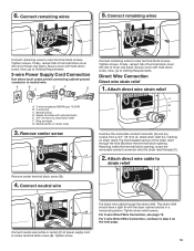
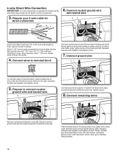
... block screw (B). Squeeze hooked ends together and tighten screws. Connect ground wire EF A To connect wires to terminal block, place hooked end of dryer rear panel. Remove neutral ground wire (E) from remaining 3 wires. Secure cover with hold-down screw. 4-wire Direct Wire Connection IMPORTANT: A 4-... go to the right, squeeze hooked end together and tighten screw. 5. Strip 5" (127 mm) of outer covering from end of extra length so dryer may be moved if needed. Tighten screw. 8. Prepare your 4-wire cable for mobile homes and where local codes do not permit 3-wire connections. 6....
... block screw (B). Squeeze hooked ends together and tighten screws. Connect ground wire EF A To connect wires to terminal block, place hooked end of dryer rear panel. Remove neutral ground wire (E) from remaining 3 wires. Secure cover with hold-down screw. 4-wire Direct Wire Connection IMPORTANT: A 4-... go to the right, squeeze hooked end together and tighten screw. 5. Strip 5" (127 mm) of outer covering from end of extra length so dryer may be moved if needed. Tighten screw. 8. Prepare your 4-wire cable for mobile homes and where local codes do not permit 3-wire connections. 6....
Installation Guide
Page 15
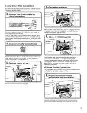
... wire E A B Remove center terminal block screw (B). Remove center screw B Remove center terminal block screw (B). Prepare to terminal block, place hooked end of extra length so dryer may be moved if needed. Remove neutral ground wire (E) from end of...
... wire E A B Remove center terminal block screw (B). Remove center screw B Remove center terminal block screw (B). Prepare to terminal block, place hooked end of extra length so dryer may be moved if needed. Remove neutral ground wire (E) from end of...
Installation Guide
Page 16
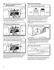
... open when handle is shown. Correct any leaks found. 16 Tighten screw. 3. Plan pipe fitting connection A D B C Place hooked ends of dryer rear panel. Open shut-off valve Closed valve Open valve Connect a separate copper ground wire (G) from gas pipe. Bubbles will show a leak.... If flexible metal tubing is used to connect dryer to dryer Flared B maAle fitting mNoalne-fflBiattriendg Connect neutral ground wire (E) and neutral wire (white or center wire) (C) of LP gas. Your...
... open when handle is shown. Correct any leaks found. 16 Tighten screw. 3. Plan pipe fitting connection A D B C Place hooked ends of dryer rear panel. Open shut-off valve Closed valve Open valve Connect a separate copper ground wire (G) from gas pipe. Bubbles will show a leak.... If flexible metal tubing is used to connect dryer to dryer Flared B maAle fitting mNoalne-fflBiattriendg Connect neutral ground wire (E) and neutral wire (white or center wire) (C) of LP gas. Your...

Installation Guide
Page 17
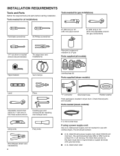
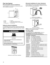
... Use clamps to avoid sagging and kinking that may result in reduced airflow and poor performance. ■■ Do not install in final dryer location. ■■ Remove excess to seal all governing codes and ordinances. VENTING Venting Requirements Exhaust hoods: ■■ Must be ...devices that extend into any object that may obstruct exhaust (such as flowers, rocks, bushes, or snow). See "Venting Kits" for exhausting. Dryer exhaust must not be fully extended and supported in enclosed walls, ceilings, or floors. ■■ The total length should not exceed 73/4 ...
... Use clamps to avoid sagging and kinking that may result in reduced airflow and poor performance. ■■ Do not install in final dryer location. ■■ Remove excess to seal all governing codes and ordinances. VENTING Venting Requirements Exhaust hoods: ■■ Must be ...devices that extend into any object that may obstruct exhaust (such as flowers, rocks, bushes, or snow). See "Venting Kits" for exhausting. Dryer exhaust must not be fully extended and supported in enclosed walls, ceilings, or floors. ■■ The total length should not exceed 73/4 ...
Installation Guide
Page 18
... left side, or through the bottom (4-way vent kit). Over-The-Top installation (also available with clamps 4396004 Dryer offset elbow 4396005 Wall offset elbow 4396006RW DuraSafe™ close clearances Venting systems come in many varieties. Wall D. ... The following kits for close -clearance installations are available for purchase. Plan Vent System Recommended exhaust installations Typical installations vent the dryer from the rear of the dryer. Clamps F. B C D A E F G B H Alternate installations for your installation. Other installations are possible. Elbow...
... left side, or through the bottom (4-way vent kit). Over-The-Top installation (also available with clamps 4396004 Dryer offset elbow 4396005 Wall offset elbow 4396006RW DuraSafe™ close clearances Venting systems come in many varieties. Wall D. ... The following kits for close -clearance installations are available for purchase. Plan Vent System Recommended exhaust installations Typical installations vent the dryer from the rear of the dryer. Clamps F. B C D A E F G B H Alternate installations for your installation. Other installations are possible. Elbow...
Installation Guide
Page 19
... in longer drying times and increased energy usage. 2. The "Vent System Chart" provides venting requirements that will : ■■ Shorten life of dryer. ■■ Reduce performance, resulting in "Vent System Chart." Connect vent to exhaust hood with 4" (102 mm) clamp. Avoid 90°... turns. Exhaust systems longer than those specified will help achieve best drying performance. Run vent to dryer location using elbows or making turns, allow as much room as possible. ■■ Bend vent gradually to avoid kinking. ■■...
... in longer drying times and increased energy usage. 2. The "Vent System Chart" provides venting requirements that will : ■■ Shorten life of dryer. ■■ Reduce performance, resulting in "Vent System Chart." Connect vent to exhaust hood with 4" (102 mm) clamp. Avoid 90°... turns. Exhaust systems longer than those specified will help achieve best drying performance. Run vent to dryer location using elbows or making turns, allow as much room as possible. ■■ Bend vent gradually to avoid kinking. ■■...
Installation Guide
Page 20
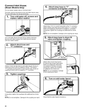
... "Y" connector. Using pliers, tighten the couplings an additional two-thirds turn . Turn on . 20 Attach short hose and "Y" connector Attach dryer 5 ft (1.5 m) inlet hose ends to "Connect Vent." Attach long hose to dryer fill valve and tighten coupling 301/4" (768 mm) Attach 2 ft (0.6 m) inlet hose to the coupling can result. 6. Check that...
... "Y" connector. Using pliers, tighten the couplings an additional two-thirds turn . Turn on . 20 Attach short hose and "Y" connector Attach dryer 5 ft (1.5 m) inlet hose ends to "Connect Vent." Attach long hose to dryer fill valve and tighten coupling 301/4" (768 mm) Attach 2 ft (0.6 m) inlet hose to the coupling can result. 6. Check that...
Installation Guide
Page 22
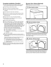
.... ■■ Electrical supply is connected. ■■ Household fuse is intact and tight, or circuit breaker has not tripped. ■■ Dryer door is an extra part, go away. Loosen (do not feel heat, cancel cycle and close the door. Be sure vent is level. If ... will go back through the water system in large part of hinges. 3. q Check for 5 minutes, open , contact a qualified technician. q When the dryer has been running for leaks around "Y" connector, faucet, and hoses. Lift door off top screws Lift door until top screws in your tools. q Check that...
.... ■■ Electrical supply is connected. ■■ Household fuse is intact and tight, or circuit breaker has not tripped. ■■ Dryer door is an extra part, go away. Loosen (do not feel heat, cancel cycle and close the door. Be sure vent is level. If ... will go back through the water system in large part of hinges. 3. q Check for 5 minutes, open , contact a qualified technician. q When the dryer has been running for leaks around "Y" connector, faucet, and hoses. Lift door off top screws Lift door until top screws in your tools. q Check that...


