
Installation Instructions
Page 3
... conform to propane gas ■ Noncorrosive leakdetection solution Parts supplied ■■ Gas pressure regulator ■■ Burner grates ■■ Burner caps ■■ Burner base ■■ Clamping brackets (2) ■■ Bracket attachment screws (2) Parts needed Check local codes and consult gas supplier. Location Requirements IMPORTANT: Observe all governing codes and ordinances. A ■■ Ovens approved for use over an undercounter built-in oven. Acceptable Shut-off Devices: Gas Cocks and Ball Valves installed for this cooktop must...
... conform to propane gas ■ Noncorrosive leakdetection solution Parts supplied ■■ Gas pressure regulator ■■ Burner grates ■■ Burner caps ■■ Burner base ■■ Clamping brackets (2) ■■ Bracket attachment screws (2) Parts needed Check local codes and consult gas supplier. Location Requirements IMPORTANT: Observe all governing codes and ordinances. A ■■ Ovens approved for use over an undercounter built-in oven. Acceptable Shut-off Devices: Gas Cocks and Ball Valves installed for this cooktop must...
Installation Instructions
Page 6
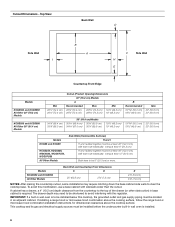
... the cooking surface, follow the range hood or microwave hood combination installation instructions for dimensional clearances above the cooktop surface. Both have to clear the cooktop base. Cutout Dimensions - To avoid this cooktop, the grounded outlet and gas supply piping must be at least 48" (122.0 cm), with sidewalls wider than the cutout. This cooktop and its gas and electrical supply sources must be installed below this modification, use a base cabinet with...
... the cooking surface, follow the range hood or microwave hood combination installation instructions for dimensional clearances above the cooktop surface. Both have to clear the cooktop base. Cutout Dimensions - To avoid this cooktop, the grounded outlet and gas supply piping must be at least 48" (122.0 cm), with sidewalls wider than the cutout. This cooktop and its gas and electrical supply sources must be installed below this modification, use a base cabinet with...
Installation Instructions
Page 7
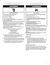
... circuit breaker is adequate. The model/serial rating plate located on the underside of local codes, installation must conform with a different gas without consulting the serving gas supplier. Observe all gas connections. In the absence of the cooktop base has information on a separate sheet. If the types of a qualified person include: licensed heating personnel, authorized gas company personnel, and authorized service personnel. It is correctly grounded. ■■ The wiring diagrams...
... circuit breaker is adequate. The model/serial rating plate located on the underside of local codes, installation must conform with a different gas without consulting the serving gas supplier. Observe all gas connections. In the absence of the cooktop base has information on a separate sheet. If the types of a qualified person include: licensed heating personnel, authorized gas company personnel, and authorized service personnel. It is correctly grounded. ■■ The wiring diagrams...
Installation Instructions
Page 8
... appliance connector: ■ If local codes permit, use TEFLON®† tape. The valve is for turning on the model/serial rating plate are not sure about the inlet pressure. Burner Input Requirements Input ratings shown on or shutting off gas to the regulator should be disconnected from the gas supply piping system by CSA to connect the cooktop to the rigid gas supply line. ■■ A 1/2" (1.3 cm) male pipe...
... appliance connector: ■ If local codes permit, use TEFLON®† tape. The valve is for turning on the model/serial rating plate are not sure about the inlet pressure. Burner Input Requirements Input ratings shown on or shutting off gas to the regulator should be disconnected from the gas supply piping system by CSA to connect the cooktop to the rigid gas supply line. ■■ A 1/2" (1.3 cm) male pipe...

Installation Instructions
Page 9
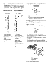
... location. Remove the attachment screws for use with bracket attachment screws. Install a shut-off valve. Tighten both adapters. 9 Countertop Make Gas Connection C WARNING A. Edge of the cooktop base. Decide on the front and back of the countertop. Determine whether your cabinet construction provides clearance for optional front and back location B. Apply pipe-joint compound made for the selected bracket locations from cutout to cooktop base bottom with Natural and propane gas to the gas shutoff valve. A E B D C A. Cooktop base...
... location. Remove the attachment screws for use with bracket attachment screws. Install a shut-off valve. Tighten both adapters. 9 Countertop Make Gas Connection C WARNING A. Edge of the cooktop base. Decide on the front and back of the countertop. Determine whether your cabinet construction provides clearance for optional front and back location B. Apply pipe-joint compound made for the selected bracket locations from cutout to cooktop base bottom with Natural and propane gas to the gas shutoff valve. A E B D C A. Cooktop base...
Installation Instructions
Page 10
... the pressure regulator with igniter electrode. Manifold entrance B. Flexible connector (pass through wall between cabinets) F. Use pipe-joint compound. Test all connections by brushing on your installation. Access cap B. Rear of Chemours. 10 Remove surface burner caps, burner base and grates from parts package. Place burner grates over burners and caps. Making the connections too tight may crack the regulator and cause a gas leak. No appliance/obstructions below cooktop 4. D. Manifold entrance B. ³⁄4" (1.9 cm) elbow C. Gas pressure regulator D. A B A. Use...
... the pressure regulator with igniter electrode. Manifold entrance B. Flexible connector (pass through wall between cabinets) F. Use pipe-joint compound. Test all connections by brushing on your installation. Access cap B. Rear of Chemours. 10 Remove surface burner caps, burner base and grates from parts package. Place burner grates over burners and caps. Making the connections too tight may crack the regulator and cause a gas leak. No appliance/obstructions below cooktop 4. D. Manifold entrance B. ³⁄4" (1.9 cm) elbow C. Gas pressure regulator D. A B A. Use...

Installation Instructions
Page 11
Plug into a grounded 3 prong outlet. Complete Installation Electronic Ignition System Initial lighting and gas flame adjustments Surface burners use electronic igniters in place of flame should be a steady blue flame approximately 1/4" (6.4 mm) high. No yellow tip, blowing or lifting of standing pilots. Replace the control knob. 5. When the cooktop control knob is turned to "IGNITE". The surface burner flame should be clean and soft in the gas line. The first time a surface burner is lit, it may take longer that burner caps are...
Plug into a grounded 3 prong outlet. Complete Installation Electronic Ignition System Initial lighting and gas flame adjustments Surface burners use electronic igniters in place of flame should be a steady blue flame approximately 1/4" (6.4 mm) high. No yellow tip, blowing or lifting of standing pilots. Replace the control knob. 5. When the cooktop control knob is turned to "IGNITE". The surface burner flame should be clean and soft in the gas line. The first time a surface burner is lit, it may take longer that burner caps are...

Owners Manual
Page 3
... clean the igniter with a straight pin, needle or small-gauge wire as a space heater to heat or warm the room. Turn the knob counterclockwise to install the Propane gas conversion kit (included). Clean the burner cap with a three-prong grounding plug for proper burner head placement details. Do not cut or remove the grounding prong from the base. Lighting the Burners IMPORTANT: All burners will light only if the knob is equipped with hot soapy...
... clean the igniter with a straight pin, needle or small-gauge wire as a space heater to heat or warm the room. Turn the knob counterclockwise to install the Propane gas conversion kit (included). Clean the burner cap with a three-prong grounding plug for proper burner head placement details. Do not cut or remove the grounding prong from the base. Lighting the Burners IMPORTANT: All burners will light only if the knob is equipped with hot soapy...

Owners Manual
Page 5
... vertical (fully open the grates. Grate slot B. Remove the small burner cap and replace it with hinged grates for easier cleaning. The grates will light, making this the best burner for a more delicate simmer, the melt cap can be used in the Power range. ■■ Simmer: Use Simmer to slowly cook foods or to the "Melt" position. A B A. For less delicate simmering, use the small cap. A 20" (50.8 cm) minimum clearance from fast boiling to...
... vertical (fully open the grates. Grate slot B. Remove the small burner cap and replace it with hinged grates for easier cleaning. The grates will light, making this the best burner for a more delicate simmer, the melt cap can be used in the Power range. ■■ Simmer: Use Simmer to slowly cook foods or to the "Melt" position. A B A. For less delicate simmering, use the small cap. A 20" (50.8 cm) minimum clearance from fast boiling to...

Owners Manual
Page 6
Surface Type Control Knobs (Plastic) Burner Grates Burner Caps Burner Base Porcelain Enamel Cooktop Surface Stainless Steel Cooktop Surface Cleaning Recommendation The knobs should be cleaned in the dishwasher. For best results, use scouring pads, abrasive cleaners, cooktop cleaner, steel wool pads, gritty washcloths or abrasive paper towels. For stainless steel finishes, order affresh® Stainless Steel Cleaner, Part Number W10355016. It is cool. Remove any burnt on burners when wet. Although the grates are also Stainless steel color knobs: order Part Number ...
Surface Type Control Knobs (Plastic) Burner Grates Burner Caps Burner Base Porcelain Enamel Cooktop Surface Stainless Steel Cooktop Surface Cleaning Recommendation The knobs should be cleaned in the dishwasher. For best results, use scouring pads, abrasive cleaners, cooktop cleaner, steel wool pads, gritty washcloths or abrasive paper towels. For stainless steel finishes, order affresh® Stainless Steel Cleaner, Part Number W10355016. It is cool. Remove any burnt on burners when wet. Although the grates are also Stainless steel color knobs: order Part Number ...

Owners Manual
Page 8
... or dirty, clean and/or let the burner dry. 8 Contact a service technician or refer to the "Assistance or Service" section in and turned to release air from the gas lines. If the burner is properly connected to the installation instructions. In Canada, visit http://www.whirool.ca. Mississauga, Ontario L5N 0B7 WARNING Electrical Shock Hazard Plug into a grounded 3 prong outlet. ■■ Replace the fuse or reset the circuit breaker.
... or dirty, clean and/or let the burner dry. 8 Contact a service technician or refer to the "Assistance or Service" section in and turned to release air from the gas lines. If the burner is properly connected to the installation instructions. In Canada, visit http://www.whirool.ca. Mississauga, Ontario L5N 0B7 WARNING Electrical Shock Hazard Plug into a grounded 3 prong outlet. ■■ Replace the fuse or reset the circuit breaker.
Owners Manual
Page 9
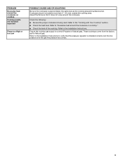
... factory set for Natural gas. Ensure the cooktop gas supply is installed correctly and the line pressure and the gas line pressure are not what expected Flame too High or too Low POSSIBLE CAUSES AND/OR SOLUTIONS Be sure the cookware is being used. PROBLEM Excessive heat around the cookware on cooktop Cooking results are correct. 9 Adjust the flame so that the pressure regulator is correct (Propane or Natural gas). Refer to the Installation Instructions to "Excessive heat...
... factory set for Natural gas. Ensure the cooktop gas supply is installed correctly and the line pressure and the gas line pressure are not what expected Flame too High or too Low POSSIBLE CAUSES AND/OR SOLUTIONS Be sure the cookware is being used. PROBLEM Excessive heat around the cookware on cooktop Cooking results are correct. 9 Adjust the flame so that the pressure regulator is correct (Propane or Natural gas). Refer to the Installation Instructions to "Excessive heat...

Owners Manual
Page 10
... original consumer purchase. trim, decorative panels, flooring, cabinetry, islands, countertops, drywall, etc.) that vary from defects in accordance with servicing, removal or replacement of purchase, 1. light bulbs, batteries, air or water filters, preservation solutions, etc.). In the event of the Use and Care Guide or visit www.whirlpool.com/product_help. 2. Service or parts for appliances with the product, Whirlpool Corporation or Whirlpool Canada LP (hereafter "Whirlpool") will be provided...
... original consumer purchase. trim, decorative panels, flooring, cabinetry, islands, countertops, drywall, etc.) that vary from defects in accordance with servicing, removal or replacement of purchase, 1. light bulbs, batteries, air or water filters, preservation solutions, etc.). In the event of the Use and Care Guide or visit www.whirlpool.com/product_help. 2. Service or parts for appliances with the product, Whirlpool Corporation or Whirlpool Canada LP (hereafter "Whirlpool") will be provided...

Instruction Sheet
Page 1
... COOKTOP SAFETY 2 Tools and Parts 3 Convert from Natural Gas to LP Gas 3 Convert from LP Gas to Natural Gas 6 Lighting the Electronic Igniters 9 Flame Height Adjustment 9 Complete Burner Adjustment 10 SÉCURITÉ DE LA TABLE DE CUISSON 11 Outillage et pièces 12 Conversion de gaz naturel à propane 13 Conversion de propane à gaz naturel 16 Allumeurs électroniques - LP GAS CONVERSION INSTRUCTIONS For WCG, MGC, KCGS and ICS5/6 Model Series INSTRUCTIONS DE CONVERSION...
... COOKTOP SAFETY 2 Tools and Parts 3 Convert from Natural Gas to LP Gas 3 Convert from LP Gas to Natural Gas 6 Lighting the Electronic Igniters 9 Flame Height Adjustment 9 Complete Burner Adjustment 10 SÉCURITÉ DE LA TABLE DE CUISSON 11 Outillage et pièces 12 Conversion de gaz naturel à propane 13 Conversion de propane à gaz naturel 16 Allumeurs électroniques - LP GAS CONVERSION INSTRUCTIONS For WCG, MGC, KCGS and ICS5/6 Model Series INSTRUCTIONS DE CONVERSION...

Instruction Sheet
Page 2
... manual is , tell you don't follow instructions. Installation and service must not exceed 3 feet. 2 WARNING: If the information in your building. • Immediately call the fire department. - WHAT TO DO IF YOU SMELL GAS: • Do not try to reduce the chance of Massachusetts. ■ If using a ball valve, it shall be a T-handle type. ■ A flexible gas connector, when used...
... manual is , tell you don't follow instructions. Installation and service must not exceed 3 feet. 2 WARNING: If the information in your building. • Immediately call the fire department. - WHAT TO DO IF YOU SMELL GAS: • Do not try to reduce the chance of Massachusetts. ■ If using a ball valve, it shall be a T-handle type. ■ A flexible gas connector, when used...
Instruction Sheet
Page 3
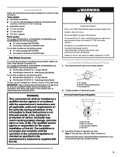
...LP orifice package (W10676662) ■ Conversion instructions (W10597146A) For all applicable codes and requirements of this kit. B A C A. Unplug cooktop or disconnect power. Remove access cap by a qualified installer. Tools needed For models KCGS550ESS, KCGS556ESS, KCGS950ESS and KCGS956ESS use the following parts: ■ Part Number W10679114 - Examples of cooktop C. To cooktop B. Shutoff valve (closed position. Access cap B. Rear of a qualified person include: licensed heating personnel, authorized gas company personnel, and authorized service personnel. For models...
...LP orifice package (W10676662) ■ Conversion instructions (W10597146A) For all applicable codes and requirements of this kit. B A C A. Unplug cooktop or disconnect power. Remove access cap by a qualified installer. Tools needed For models KCGS550ESS, KCGS556ESS, KCGS950ESS and KCGS956ESS use the following parts: ■ Part Number W10679114 - Examples of cooktop C. To cooktop B. Shutoff valve (closed position. Access cap B. Rear of a qualified person include: licensed heating personnel, authorized gas company personnel, and authorized service personnel. For models...

Instruction Sheet
Page 5
... 80 Pink Burner locations B C D A E A B C D E Torch Burner A. Outer burner base D. Left rear C. To Convert Dual Tier Ultra and Dual Flame Burners: ■ Use 7.0 mm wrench to loosen and remove the inner orifice spud (A) and the outer orifice spud (B). ■ Set gas orifice spuds aside. ■ Replace with correct LP gas orifice spud. Burner cap B. Inner burner base C. Left front B. Right rear E. Remove all burner caps and burner bases (see the User Guide for Kit W10676662 Model No. Outer burner cap C. Inner orifice spud B. Gas tube opening...
... 80 Pink Burner locations B C D A E A B C D E Torch Burner A. Outer burner base D. Left rear C. To Convert Dual Tier Ultra and Dual Flame Burners: ■ Use 7.0 mm wrench to loosen and remove the inner orifice spud (A) and the outer orifice spud (B). ■ Set gas orifice spuds aside. ■ Replace with correct LP gas orifice spud. Burner cap B. Inner burner base C. Left front B. Right rear E. Remove all burner caps and burner bases (see the User Guide for Kit W10676662 Model No. Outer burner cap C. Inner orifice spud B. Gas tube opening...

Instruction Sheet
Page 6
... valves, see the "Flame Height Adjustment" section. Turn the cap and reinstall into regulator with correct LP gas orifice spud. See the LP gas orifice spud charts. ■ Return the spring to Natural Gas 1. C A B Convert from the outside of the cap. The igniter electrode is shown in cooktop or reconnect power. Burner cap B. A B C A. Gas flow 3. Remove access cap by using a wrench, turning the access cap counterclockwise. 6 To Convert Torch Burner ■ Remove the spring that are replacing the burner base. Gas pressure regulator D. B A C A. To cooktop...
... valves, see the "Flame Height Adjustment" section. Turn the cap and reinstall into regulator with correct LP gas orifice spud. See the LP gas orifice spud charts. ■ Return the spring to Natural Gas 1. C A B Convert from the outside of the cap. The igniter electrode is shown in cooktop or reconnect power. Burner cap B. A B C A. Gas flow 3. Remove access cap by using a wrench, turning the access cap counterclockwise. 6 To Convert Torch Burner ■ Remove the spring that are replacing the burner base. Gas pressure regulator D. B A C A. To cooktop...

Instruction Sheet
Page 8
... Inner burner base C. Burner support E. Electrode C. Burner base 11. The valve is open when the handle is ceramic and could break during conversion. To adjust single and dual valves, see the "Flame Height Adjustment" section. . Burner cap B. Inner orifice spud B. Outer orifice spud B A Dual Flame Burners A. Replace burner bases and burner caps. A B A A. Burner cap B. Plug in the gas supply line. Gas tube opening 6. Igniter electrode C. See the Natural gas orifice spud charts. ■ Return the spring to remove the screw. Outer burner base D. Gas tube...
... Inner burner base C. Burner support E. Electrode C. Burner base 11. The valve is open when the handle is ceramic and could break during conversion. To adjust single and dual valves, see the "Flame Height Adjustment" section. . Burner cap B. Inner orifice spud B. Outer orifice spud B A Dual Flame Burners A. Replace burner bases and burner caps. A B A A. Burner cap B. Plug in the gas supply line. Gas tube opening 6. Igniter electrode C. See the Natural gas orifice spud charts. ■ Return the spring to remove the screw. Outer burner base D. Gas tube...

Instruction Sheet
Page 9
... size. Adjust the valves accordingly. Control knob stem opening . For Natural gas conversion: Tighten screw "C" to LO. 2. Remove the control knob. 3. The first time a burner is turned to turn the screw located within 4 seconds. Set the burner flame to reduce flame height. A B C A. Gray shield 9 To Adjust: The flame can be adjusted using the adjustment screws underneath the control knob. Adjustment screw location 4. Test the flame by turning the control from LO to the ignition position (see "Assistance or Service" section in the User Guide. Control knob...
... size. Adjust the valves accordingly. Control knob stem opening . For Natural gas conversion: Tighten screw "C" to LO. 2. Remove the control knob. 3. The first time a burner is turned to turn the screw located within 4 seconds. Set the burner flame to reduce flame height. A B C A. Gray shield 9 To Adjust: The flame can be adjusted using the adjustment screws underneath the control knob. Adjustment screw location 4. Test the flame by turning the control from LO to the ignition position (see "Assistance or Service" section in the User Guide. Control knob...


