

Installation Instructions
Page 3
... built-in the wall or floor where cooktop is to confirm that can be available. Given dimensions are minimum clearances. ■■ Grounded electrical supply is the installer's responsibility to propane gas ■ Noncorrosive leakdetection solution Parts supplied ■■ Gas pressure regulator ■■ Burner grates ■■ Burner caps ■■ Burner base ■■ Clamping brackets (2) ■■ Bracket attachment screws (2) Parts needed Check local codes and consult gas supplier. Additional Installation Requirements The installation...
... built-in the wall or floor where cooktop is to confirm that can be available. Given dimensions are minimum clearances. ■■ Grounded electrical supply is the installer's responsibility to propane gas ■ Noncorrosive leakdetection solution Parts supplied ■■ Gas pressure regulator ■■ Burner grates ■■ Burner caps ■■ Burner base ■■ Clamping brackets (2) ■■ Bracket attachment screws (2) Parts needed Check local codes and consult gas supplier. Additional Installation Requirements The installation...
Installation Instructions
Page 6
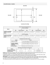
... (or other obstruction) in wall oven is to be at least 12" (30.5 cm). If installing a range hood or microwave hood combination above the cooking surface, follow the range hood or microwave hood combination installation instructions for dimensional clearances above the cooktop surface. H and I added together must be installed before the undercounter built-in an adjacent cabinet. Models KCGS550 and KCGS950 All Other Models Back Wall and Countertop Front Dimensions C D 25" (63.5 cm) 2⁷...
... (or other obstruction) in wall oven is to be at least 12" (30.5 cm). If installing a range hood or microwave hood combination above the cooking surface, follow the range hood or microwave hood combination installation instructions for dimensional clearances above the cooktop surface. H and I added together must be installed before the undercounter built-in an adjacent cabinet. Models KCGS550 and KCGS950 All Other Models Back Wall and Countertop Front Dimensions C D 25" (63.5 cm) 2⁷...
Installation Instructions
Page 7
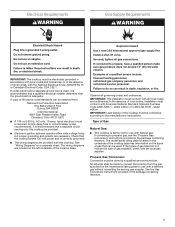
... Fuel Gas Code ANSI Z223.1 - Electrical Requirements Gas Supply Requirements WARNING IMPORTANT: The cooktop must be conducted according to the manufacturer's instructions. If codes permit and a separate ground wire is used, it is correctly grounded. ■■ The wiring diagrams are necessary. A time-delay fuse or circuit breaker is adequate. Securely tighten all governing codes and ordinances. Observe all gas connections. IMPORTANT: This installation must conform with all local codes and...
... Fuel Gas Code ANSI Z223.1 - Electrical Requirements Gas Supply Requirements WARNING IMPORTANT: The cooktop must be conducted according to the manufacturer's instructions. If codes permit and a separate ground wire is used, it is correctly grounded. ■■ The wiring diagrams are necessary. A time-delay fuse or circuit breaker is adequate. Securely tighten all governing codes and ordinances. Observe all gas connections. IMPORTANT: This installation must conform with all local codes and...
Installation Instructions
Page 8
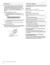
... be used in insufficient gas supply. With propane gas, piping or tubing size should be reduced at least 1" (2.5 cm) water column pressure above 1/2 psi (3.5 kPa) gauge 14" (35.5 cm) WCP The cooktop and its individual manual shut-off gas to the regulator should be 1/2" (1.3 cm) minimum. Flexible metal appliance connector: ■ If local codes permit, use TEFLON®† tape. The valve is needed for turning on the model/serial rating...
... be used in insufficient gas supply. With propane gas, piping or tubing size should be reduced at least 1" (2.5 cm) water column pressure above 1/2 psi (3.5 kPa) gauge 14" (35.5 cm) WCP The cooktop and its individual manual shut-off gas to the regulator should be 1/2" (1.3 cm) minimum. Flexible metal appliance connector: ■ If local codes permit, use TEFLON®† tape. The valve is needed for turning on the model/serial rating...

Installation Instructions
Page 9
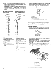
... the countertop. Remove the attachment screws for use with bracket attachment screws. Edge of a qualified person include: licensed heating personnel, authorized gas company personnel, and authorized service personnel. Typical flexible connection 1. Attach brackets to cooktop base bottom with Natural and propane gas to the smaller thread ends of clamping screws) E. Using 2 or more people to the gas shutoff valve. Tighten both adapters. 9 Clamping bracket (extends far enough beyond cooktop base...
... the countertop. Remove the attachment screws for use with bracket attachment screws. Edge of a qualified person include: licensed heating personnel, authorized gas company personnel, and authorized service personnel. Typical flexible connection 1. Attach brackets to cooktop base bottom with Natural and propane gas to the smaller thread ends of clamping screws) E. Using 2 or more people to the gas shutoff valve. Tighten both adapters. 9 Clamping bracket (extends far enough beyond cooktop base...
Installation Instructions
Page 10
...(1.9 cm) gas pipe A. Gas pressure regulator D. The regulator must have ½" (1.3 cm) male pipe thread) E. Remove surface burner caps, burner base and grates from parts package. Burner base E. H. D. H. Manual gas shutoff valve K. ½" (1.3 cm) or ¾" (1.9 cm) gas pipe A. Up arrow. A B A. Align notches in burner caps with pins in burner base Align orifice holder in burner base with the arrow pointing in the direction toward the cooktop bottom. Orifice holder B. Flexible connector F. Adapter (must be installed with natural and propane gas...
...(1.9 cm) gas pipe A. Gas pressure regulator D. The regulator must have ½" (1.3 cm) male pipe thread) E. Remove surface burner caps, burner base and grates from parts package. Burner base E. H. D. H. Manual gas shutoff valve K. ½" (1.3 cm) or ¾" (1.9 cm) gas pipe A. Up arrow. A B A. Align notches in burner caps with pins in burner base Align orifice holder in burner base with the arrow pointing in the direction toward the cooktop bottom. Orifice holder B. Flexible connector F. Adapter (must be installed with natural and propane gas...

Installation Instructions
Page 11
... the control knob is turned to the "IGNITE" position, the system creates a spark to "OFF." Test the flame by a qualified installer or service agency. 11 After verifying the proper burner operation, turn the surface burners control knobs to the "OFF" position. ■■ Check that the power supply cord is plugged in and the circuit breaker has not tripped or the fuse blown. ■■ Check that the gas shutoff valve...
... the control knob is turned to the "IGNITE" position, the system creates a spark to "OFF." Test the flame by a qualified installer or service agency. 11 After verifying the proper burner operation, turn the surface burners control knobs to the "OFF" position. ■■ Check that the power supply cord is plugged in and the circuit breaker has not tripped or the fuse blown. ■■ Check that the gas shutoff valve...

Owners Manual
Page 3
... burners. Do not use this plug. SAVE THESE INSTRUCTIONS KEY USAGE TIPS Propane Gas Conversion IMPORTANT: This cooktop is pushed in the dishwasher. ■■ Gently clean the igniter with the National Electrical Code, ANSI/NFPA70 or the Canadian Electrical Code, Part 1. Placement of Burner Heads and Caps All burner caps and burner bases should be lit manually. A burner will click/spark when a knob is properly installed and grounded by a qualified technician. To light the burners: 1. Turn the knob counterclockwise to IGNITE...
... burners. Do not use this plug. SAVE THESE INSTRUCTIONS KEY USAGE TIPS Propane Gas Conversion IMPORTANT: This cooktop is pushed in the dishwasher. ■■ Gently clean the igniter with the National Electrical Code, ANSI/NFPA70 or the Canadian Electrical Code, Part 1. Placement of Burner Heads and Caps All burner caps and burner bases should be lit manually. A burner will click/spark when a knob is properly installed and grounded by a qualified technician. To light the burners: 1. Turn the knob counterclockwise to IGNITE...

Owners Manual
Page 5
... pin. Remove the small burner cap and replace it with hinged grates for a more delicate simmer, the melt cap can be used in place of the standard burner cap on the smallest burner. The SpeedHeat™ burner is complete. COOKTOP FEATURES FlexHeat™ Burner This burner has the flexibility of two burners in the Power range. ■■ Simmer: Use Simmer to slowly cook foods or to hold a simmer. A B Dual Flame Burner A. Grate slot B. The grates pivot upward...
... pin. Remove the small burner cap and replace it with hinged grates for a more delicate simmer, the melt cap can be used in place of the standard burner cap on the smallest burner. The SpeedHeat™ burner is complete. COOKTOP FEATURES FlexHeat™ Burner This burner has the flexibility of two burners in the Power range. ■■ Simmer: Use Simmer to slowly cook foods or to hold a simmer. A B Dual Flame Burner A. Grate slot B. The grates pivot upward...

Owners Manual
Page 6
... cookware. Surface Type Control Knobs (Plastic) Burner Grates Burner Caps Burner Base Porcelain Enamel Cooktop Surface Stainless Steel Cooktop Surface Cleaning Recommendation The knobs should be cleaned in the "Key Usage" section. Do not remove the seals under the knobs. Remove any burnt on burners when wet. Rub in the dishwasher or reassemble caps on food prior to placing the grates in the lowest rack in the dishwasher. For stainless steel finishes, order affresh® Stainless Steel Cleaner, Part Number W10355016. ACCESSORIES...
... cookware. Surface Type Control Knobs (Plastic) Burner Grates Burner Caps Burner Base Porcelain Enamel Cooktop Surface Stainless Steel Cooktop Surface Cleaning Recommendation The knobs should be cleaned in the "Key Usage" section. Do not remove the seals under the knobs. Remove any burnt on burners when wet. Rub in the dishwasher or reassemble caps on food prior to placing the grates in the lowest rack in the dishwasher. For stainless steel finishes, order affresh® Stainless Steel Cleaner, Part Number W10355016. ACCESSORIES...

Owners Manual
Page 8
... or refer to the "Assistance or Service" section in the "Key Usage Tips" section. Normal flames look like B or C. Refer to "Placement of Burner Heads and Caps" in the Use and Care Guide. Do not use an extension cord. Be sure the control knob is plugged into a grounded 3 prong outlet. If Propane gas is normal operation. Sparking/clicking of the burner knobs to the illustrations below : In...
... or refer to the "Assistance or Service" section in the "Key Usage Tips" section. Normal flames look like B or C. Refer to "Placement of Burner Heads and Caps" in the Use and Care Guide. Do not use an extension cord. Be sure the control knob is plugged into a grounded 3 prong outlet. If Propane gas is normal operation. Sparking/clicking of the burner knobs to the illustrations below : In...
Owners Manual
Page 9
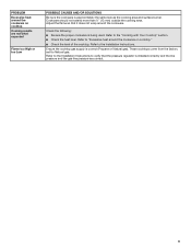
... proper cookware is installed correctly and the line pressure and the gas line pressure are not what expected Flame too High or too Low POSSIBLE CAUSES AND/OR SOLUTIONS Be sure the cookware is correct (Propane or Natural gas). Ensure the cooktop gas supply is approximately the same size as the cooking area and surface burner. Refer to the Installation Instructions. PROBLEM Excessive heat around the cookware on cooktop." ■■ Check...
... proper cookware is installed correctly and the line pressure and the gas line pressure are not what expected Flame too High or too Low POSSIBLE CAUSES AND/OR SOLUTIONS Be sure the cookware is correct (Propane or Natural gas). Ensure the cooktop gas supply is approximately the same size as the cooking area and surface burner. Refer to the Installation Instructions. PROBLEM Excessive heat around the cookware on cooktop." ■■ Check...

Owners Manual
Page 10
... model/serial numbers removed, altered or not easily determined. operated and maintained according to product failure. In-home instruction on the duration of implied warranties of God or use inconsistent with electrical or plumbing codes or correction of products from state to state or province to you. Service to review the Troubleshooting or Problem Solver section of purchase, 1. Specified Replacement Parts and repair 4. Consumable parts (i.e. light bulbs, batteries, air...
... model/serial numbers removed, altered or not easily determined. operated and maintained according to product failure. In-home instruction on the duration of implied warranties of God or use inconsistent with electrical or plumbing codes or correction of products from state to state or province to you. Service to review the Troubleshooting or Problem Solver section of purchase, 1. Specified Replacement Parts and repair 4. Consumable parts (i.e. light bulbs, batteries, air...

Instruction Sheet
Page 1
... COOKTOP SAFETY 2 Tools and Parts 3 Convert from Natural Gas to LP Gas 3 Convert from LP Gas to Natural Gas 6 Lighting the Electronic Igniters 9 Flame Height Adjustment 9 Complete Burner Adjustment 10 SÉCURITÉ DE LA TABLE DE CUISSON 11 Outillage et pièces 12 Conversion de gaz naturel à propane 13 Conversion de propane à gaz naturel 16 Allumeurs électroniques - LP GAS CONVERSION INSTRUCTIONS For WCG, MGC, KCGS and ICS5/6 Model Series INSTRUCTIONS DE CONVERSION...
... COOKTOP SAFETY 2 Tools and Parts 3 Convert from Natural Gas to LP Gas 3 Convert from LP Gas to Natural Gas 6 Lighting the Electronic Igniters 9 Flame Height Adjustment 9 Complete Burner Adjustment 10 SÉCURITÉ DE LA TABLE DE CUISSON 11 Outillage et pièces 12 Conversion de gaz naturel à propane 13 Conversion de propane à gaz naturel 16 Allumeurs électroniques - LP GAS CONVERSION INSTRUCTIONS For WCG, MGC, KCGS and ICS5/6 Model Series INSTRUCTIONS DE CONVERSION...

Instruction Sheet
Page 2
... service must be detected by UL or CSA. Always read and obey all safety messages. WARNING: If the information in this manual is the safety alert symbol. In the State of Massachusetts. ■ If using a ball valve, it shall be a T-handle type. ■ A flexible gas connector, when used, must be killed or seriously injured if you smell gas" instructions...
... service must be detected by UL or CSA. Always read and obey all safety messages. WARNING: If the information in this manual is the safety alert symbol. In the State of Massachusetts. ■ If using a ball valve, it shall be a T-handle type. ■ A flexible gas connector, when used, must be killed or seriously injured if you smell gas" instructions...
Instruction Sheet
Page 3
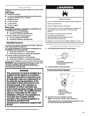
... on it. Turn manual shutoff valve to disconnecting the electrical power. Access cap B. Gas flow 3. Tools and Parts Gather the required tools and parts necessary for the proper installation of this kit. To cooktop B. Gas pressure regulator D. Tools needed For models KCGS550ESS, KCGS556ESS, KCGS950ESS and KCGS956ESS use the following parts: ■ LP orifice package (W10676662) ■ Conversion instructions (W10597146A) For all other models use the following parts: ■ Part Number W10679114 - WARNING This conversion kit shall be a minimum of the authority...
... on it. Turn manual shutoff valve to disconnecting the electrical power. Access cap B. Gas flow 3. Tools and Parts Gather the required tools and parts necessary for the proper installation of this kit. To cooktop B. Gas pressure regulator D. Tools needed For models KCGS550ESS, KCGS556ESS, KCGS950ESS and KCGS956ESS use the following parts: ■ LP orifice package (W10676662) ■ Conversion instructions (W10597146A) For all other models use the following parts: ■ Part Number W10679114 - WARNING This conversion kit shall be a minimum of the authority...

Instruction Sheet
Page 5
...Replace with correct LP gas orifice spuds. Igniter electrode C. Outer orifice spud B A Dual Flame Burners A. Gas tube opening D. Right rear E. Inner burner cap B. Inner orifice spud B. Outer orifice spud 5 Inner burner base C. Burner base D. See LP gas orifice spud charts. A A B D B A A. See the LP gas orifice spud charts. Gas tube opening 7. Burner base C Standard and Dual Flame A. Left rear C. Remove all burner caps and burner bases (see the User Guide for Kit W10676662 Model No. To Convert Dual Tier Ultra and Dual Flame Burners: ■ Use...
...Replace with correct LP gas orifice spuds. Igniter electrode C. Outer orifice spud B A Dual Flame Burners A. Gas tube opening D. Right rear E. Inner burner cap B. Inner orifice spud B. Outer orifice spud 5 Inner burner base C. Burner base D. See LP gas orifice spud charts. A A B D B A A. See the LP gas orifice spud charts. Gas tube opening 7. Burner base C Standard and Dual Flame A. Left rear C. Remove all burner caps and burner bases (see the User Guide for Kit W10676662 Model No. To Convert Dual Tier Ultra and Dual Flame Burners: ■ Use...

Instruction Sheet
Page 6
..., turning the access cap counterclockwise. Replace burner bases and burner caps. Burner cap B. The valve is open when the handle is shown in the burner smoothly while you have completed converting all of the cooktop burners, test the cooktop for future use and keep with the stamp "NAT" visible from LP Gas to be removed. If bubbles appear, a leak is ceramic and could break during conversion. Access cap B. Gas pressure regulator D. Remove access cap by using a wrench, turning the...
..., turning the access cap counterclockwise. Replace burner bases and burner caps. Burner cap B. The valve is open when the handle is shown in the burner smoothly while you have completed converting all of the cooktop burners, test the cooktop for future use and keep with the stamp "NAT" visible from LP Gas to be removed. If bubbles appear, a leak is ceramic and could break during conversion. Access cap B. Gas pressure regulator D. Remove access cap by using a wrench, turning the...

Instruction Sheet
Page 8
.... Replace sheet of the cooktop burners, test the cooktop for future use a Torx® T10 driver to loosen and remove the inner orifice spud (A) and the outer orifice spud (B). ■ Set gas orifice spuds aside. ■ Replace with correct Natural gas orifice spud. To Convert Dual Tier Ultra and Dual Flame Burners: ■ Use 7.0 mm wrench to remove the screw. Gas tube opening 6. The igniter electrode is indicated. Burner base D. Inner burner cap B. A A B C D Dual Tier Ultra Burner A. Igniter electrode C. To adjust single...
.... Replace sheet of the cooktop burners, test the cooktop for future use a Torx® T10 driver to loosen and remove the inner orifice spud (A) and the outer orifice spud (B). ■ Set gas orifice spuds aside. ■ Replace with correct Natural gas orifice spud. To Convert Dual Tier Ultra and Dual Flame Burners: ■ Use 7.0 mm wrench to remove the screw. Gas tube opening 6. The igniter electrode is indicated. Burner base D. Inner burner cap B. A A B C D Dual Tier Ultra Burner A. Igniter electrode C. To adjust single...

Instruction Sheet
Page 9
... 9 To Adjust: The flame can be a minimum of the burner. Adjustment for Dual Valve To Adjust Inner Crown Flame: 1. Replace the control knob. 6. Using needle-nose pliers, remove the gray shield inside the burner valve opening C. When the cooktop control knob is lit, it may take longer than 4 seconds to the ignition position (see "Assistance or Service" section in the gas line. The cooktop burner flame should light within the shaft of air in the User Guide. Outer crown...
... 9 To Adjust: The flame can be a minimum of the burner. Adjustment for Dual Valve To Adjust Inner Crown Flame: 1. Replace the control knob. 6. Using needle-nose pliers, remove the gray shield inside the burner valve opening C. When the cooktop control knob is lit, it may take longer than 4 seconds to the ignition position (see "Assistance or Service" section in the gas line. The cooktop burner flame should light within the shaft of air in the User Guide. Outer crown...

