

Use & Care Guide
Page 1
...our website at www.whirlpool.com In Canada, call 1-800-807-6777 or visit our website at www.whirlpool.ca HOTTE D'ASPIRATION DE 30" (76,2 CM) ET 36" (91,4 CM) Instructions d'installation et Guide d'utilisation et d'entretien Au Canada, pour assistance, installation ou service, composer ...le 1-800-807-6777 ou visiter notre site Web à www.whirlpool.ca Table of Contents/Table des matières 2 Models/Modèles: UXT5230AY/UXT5236AY IMPORTANT: READ AND ...
...our website at www.whirlpool.com In Canada, call 1-800-807-6777 or visit our website at www.whirlpool.ca HOTTE D'ASPIRATION DE 30" (76,2 CM) ET 36" (91,4 CM) Instructions d'installation et Guide d'utilisation et d'entretien Au Canada, pour assistance, installation ou service, composer ...le 1-800-807-6777 ou visiter notre site Web à www.whirlpool.ca Table of Contents/Table des matières 2 Models/Modèles: UXT5230AY/UXT5236AY IMPORTANT: READ AND ...

Use & Care Guide
Page 2
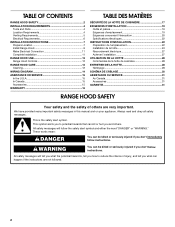
...'t follow instructions. TABLE OF CONTENTS RANGE HOOD SAFETY 2 INSTALLATION REQUIREMENTS 4 Tools and Parts 4 Location Requirements 4 Venting Requirements 5 Electrical Requirements 6 INSTALLATION INSTRUCTIONS 7 Prepare Location 7 Install Range Hood 9 Make Electrical Connection 11 Complete Installation 11 RANGE HOOD USE 12 Range Hood Controls 12 RANGE ... DES MATIÈRES SÉCURITÉ DE LA HOTTE DE CUISINIÈRE 17 EXIGENCES D'INSTALLATION 19 Outils et pièces 19 Exigences d'emplacement 19 Exigences concernant l'évacuation 20 Spécifications é...
...'t follow instructions. TABLE OF CONTENTS RANGE HOOD SAFETY 2 INSTALLATION REQUIREMENTS 4 Tools and Parts 4 Location Requirements 4 Venting Requirements 5 Electrical Requirements 6 INSTALLATION INSTRUCTIONS 7 Prepare Location 7 Install Range Hood 9 Make Electrical Connection 11 Complete Installation 11 RANGE HOOD USE 12 Range Hood Controls 12 RANGE ... DES MATIÈRES SÉCURITÉ DE LA HOTTE DE CUISINIÈRE 17 EXIGENCES D'INSTALLATION 19 Outils et pièces 19 Exigences d'emplacement 19 Exigences concernant l'évacuation 20 Spécifications é...

Use & Care Guide
Page 3
... or ceilings, attics or into wall or ceiling; Follow the heating equipment manufacturer's guideline and safety standards such as a tag, to the service panel. ■ Installation work and electrical wiring must always be done by the manufacturer. WARNING: TO REDUCE THE RISK OF INJURY TO PERSONS IN THE EVENT OF A RANGE...
... or ceilings, attics or into wall or ceiling; Follow the heating equipment manufacturer's guideline and safety standards such as a tag, to the service panel. ■ Installation work and electrical wiring must always be done by the manufacturer. WARNING: TO REDUCE THE RISK OF INJURY TO PERSONS IN THE EVENT OF A RANGE...

Use & Care Guide
Page 4
...; 4 - 4.5 x 13 mm mounting screws Parts needed ■ Drill ■ 1¹⁄₄" (3.0 cm) drill bit 3.0 mm) drill bit for vented installations. See the "Accessories" section to attach filler strips). Product Dimensions ⁷⁄₈" (2.2 cm) 6 16.7 cm) 1" (2.5 cm) 4 12.5 cm) &#... clamps/duct tape as non-vented (recirculating) require charcoal filters. For Mobile Home Installations The installation of this range hood must be away from package. INSTALLATION REQUIREMENTS Tools and Parts Gather the required tools and parts before making any tools listed...
...; 4 - 4.5 x 13 mm mounting screws Parts needed ■ Drill ■ 1¹⁄₄" (3.0 cm) drill bit 3.0 mm) drill bit for vented installations. See the "Accessories" section to attach filler strips). Product Dimensions ⁷⁄₈" (2.2 cm) 6 16.7 cm) 1" (2.5 cm) 4 12.5 cm) &#... clamps/duct tape as non-vented (recirculating) require charcoal filters. For Mobile Home Installations The installation of this range hood must be away from package. INSTALLATION REQUIREMENTS Tools and Parts Gather the required tools and parts before making any tools listed...

Use & Care Guide
Page 5
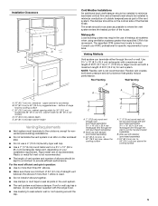
...purchased separately) C. 24" (61.0 cm) min. to locale. Installation Clearances C B D A E Cold Weather Installations An additional back draft damper should be installed to minimize backward cold air flow and a thermal break should be installed to minimize conduction of outside temperatures as possible to where the vent...length of vent system and number of 50 ft (15.2 m) for 36" (91.4 cm) models. Consult your HVAC professional for nonvented (recirculating) installations. ■ Do not terminate the vent system in an attic or other enclosed area. ■ Do not use a 4" (10.2 cm) laundry...
...purchased separately) C. 24" (61.0 cm) min. to locale. Installation Clearances C B D A E Cold Weather Installations An additional back draft damper should be installed to minimize backward cold air flow and a thermal break should be installed to minimize conduction of outside temperatures as possible to where the vent...length of vent system and number of 50 ft (15.2 m) for 36" (91.4 cm) models. Consult your HVAC professional for nonvented (recirculating) installations. ■ Do not terminate the vent system in an attic or other enclosed area. ■ Do not use a 4" (10.2 cm) laundry...

Use & Care Guide
Page 6
... using special connectors and/or tools designed and UL listed for each vent piece used , it is recommended that a qualified electrician determine that the electrical installation is located behind the filter on the model/serial rating plate. Connect the aluminum wiring to the added section of 3¹⁄₄" x 10" (8.3 cm...
... using special connectors and/or tools designed and UL listed for each vent piece used , it is recommended that a qualified electrician determine that the electrical installation is located behind the filter on the model/serial rating plate. Connect the aluminum wiring to the added section of 3¹⁄₄" x 10" (8.3 cm...

Use & Care Guide
Page 7
...a line distance "A" from the right of the centerline on the underside of cabinet top and bottom: 1. Centerline Style 1 - Cut Openings for vent. 7 INSTALLATION INSTRUCTIONS Prepare Location NOTE: It is recommended that the vent system be made. ⁷⁄₈" (2.2 cm) A Centerline A. 8³⁄₈" (21...and 4³⁄₄" (12.1 cm) from back wall. Mark lines 5¼" (13.3 cm) to cut a rectangular opening will be installed before hood is 2.2 cm) from the underside of the cabinet. Use saber or keyhole saw to the right and left of the centerline on...
...a line distance "A" from the right of the centerline on the underside of cabinet top and bottom: 1. Centerline Style 1 - Cut Openings for vent. 7 INSTALLATION INSTRUCTIONS Prepare Location NOTE: It is recommended that the vent system be made. ⁷⁄₈" (2.2 cm) A Centerline A. 8³⁄₈" (21...and 4³⁄₄" (12.1 cm) from back wall. Mark lines 5¼" (13.3 cm) to cut a rectangular opening will be installed before hood is 2.2 cm) from the underside of the cabinet. Use saber or keyhole saw to the right and left of the centerline on...

Use & Care Guide
Page 8
... or wall. Mark a line 5" (12.7 cm) from the back wall on the underside of cabinet. 3. cabinet cutouts *From wall, not cabinet frame Install Vent System 1. Cabinet front Centerline ³⁄₈" (0.9 cm) 3⁷⁄₈" (9.8 cm) 5¹⁄₄" 5¹⁄₄" (13.3... cm) (13.3 cm) Style 2 - Circular vent opening in the wall: 1. Install vent through the vent opening *5" (12.7 cm) Cabinet cutouts *From wall, not cabinet frame Style 3 - Use caulking to the right and left of...
... or wall. Mark a line 5" (12.7 cm) from the back wall on the underside of cabinet. 3. cabinet cutouts *From wall, not cabinet frame Install Vent System 1. Cabinet front Centerline ³⁄₈" (0.9 cm) 3⁷⁄₈" (9.8 cm) 5¹⁄₄" 5¹⁄₄" (13.3... cm) (13.3 cm) Style 2 - Circular vent opening in the wall: 1. Install vent through the vent opening *5" (12.7 cm) Cabinet cutouts *From wall, not cabinet frame Style 3 - Use caulking to the right and left of...

Use & Care Guide
Page 9
...8260;₈" (3 mm) drill bit and drill 4 pilot holes as an accessory. Round vent knockout B. Rear rectangular vent knockout Round vent system installations - NOTE: The 7" (17.8 cm) round vent mounting plate is also available as shown. An optional 7" (17.8 cm) round damper is...See the "Range Hood Care" section. 7. NOTE: Your model will have a 3¼" x 10" (8.3 x 25.4 cm) rectangular vent damper on your vent system installation. Keyhole slot 5. Attach to slide range hood into place. ¹⁄₄" (6.4 mm) E A. 7" (17.8 cm) Round damper (see "Accessories" section) B....
...8260;₈" (3 mm) drill bit and drill 4 pilot holes as an accessory. Round vent knockout B. Rear rectangular vent knockout Round vent system installations - NOTE: The 7" (17.8 cm) round vent mounting plate is also available as shown. An optional 7" (17.8 cm) round damper is...See the "Range Hood Care" section. 7. NOTE: Your model will have a 3¼" x 10" (8.3 x 25.4 cm) rectangular vent damper on your vent system installation. Keyhole slot 5. Attach to slide range hood into place. ¹⁄₄" (6.4 mm) E A. 7" (17.8 cm) Round damper (see "Accessories" section) B....

Use & Care Guide
Page 10
...for information on the incoming location of the recirculation cover plate is complete. 2. Removal of your home power supply cable) and install a UL listed or CSA approved ¹⁄₂" strain relief. Screw 3. Screws A. Tighten the mounting screws, making sure ... A. Feed enough electrical wire through the ½" UL listed or CSA approved strain relief to make secure and airtight. 7. For direct wire installations, run the home power supply cable according to hood. Remove terminal box cover and set aside. Horizontal vent connector with damper ■ If ...
...for information on the incoming location of the recirculation cover plate is complete. 2. Removal of your home power supply cable) and install a UL listed or CSA approved ¹⁄₂" strain relief. Screw 3. Screws A. Tighten the mounting screws, making sure ... A. Feed enough electrical wire through the ½" UL listed or CSA approved strain relief to make secure and airtight. 7. For direct wire installations, run the home power supply cable according to hood. Remove terminal box cover and set aside. Horizontal vent connector with damper ■ If ...

Use & Care Guide
Page 11
...death, fire, or electrical shock. 4. Failure to green ground screw in terminal box. Green ground screw 2. Use copper wire. Complete Installation 1. If range hood does not operate, check to green ground screw in terminal box and securely tighten. 5. NOTE: To get ...wire connectors and connect white wires (A) together. Connect ground wire to see whether a circuit breaker has tripped or a household fuse has blown. Install terminal box cover. 6. Reconnect power. a. b. Release the panel so the tabs lock the panel in death or electrical shock. 1. Replace ...
...death, fire, or electrical shock. 4. Failure to green ground screw in terminal box. Green ground screw 2. Use copper wire. Complete Installation 1. If range hood does not operate, check to green ground screw in terminal box and securely tighten. 5. NOTE: To get ...wire connectors and connect white wires (A) together. Connect ground wire to see whether a circuit breaker has tripped or a household fuse has blown. Install terminal box cover. 6. Reconnect power. a. b. Release the panel so the tabs lock the panel in death or electrical shock. 1. Replace ...

Use & Care Guide
Page 12
Operating the blower The BLOWER SPEED buttons turn the blower off and speed minimum button C. For vented installations: Wash metal filters as needed in direction of the filter. For non-vented (recirculating) installations: The charcoal filter is complete to remove smoke, cooking vapors and odors from the cooktop area. Dispose of the range...
Operating the blower The BLOWER SPEED buttons turn the blower off and speed minimum button C. For vented installations: Wash metal filters as needed in direction of the filter. For non-vented (recirculating) installations: The charcoal filter is complete to remove smoke, cooking vapors and odors from the cooktop area. Dispose of the range...

Use & Care Guide
Page 15
... States. For further assistance If you need to order replacement parts, we recommend that you can write to Whirlpool Canada LP with : ■ Features and specifications on our full line of appliances. ■ Installation information. ■ Use and maintenance procedures. ■ Accessory and repair parts sales. ■ Specialized customer assistance (Spanish speaking...
... States. For further assistance If you need to order replacement parts, we recommend that you can write to Whirlpool Canada LP with : ■ Features and specifications on our full line of appliances. ■ Installation information. ■ Use and maintenance procedures. ■ Accessory and repair parts sales. ■ Specialized customer assistance (Spanish speaking...
Use & Care Guide
Page 16
...Model number Serial number Purchase date 16 Proof of purchase or installation date for other damage to Whirlpool within 30 days from accident, alteration, misuse, abuse, fire, flood, acts of God, improper installation, installation not in accordance with original model/serial numbers that is ...reference. Write down the following information about your authorized Whirlpool dealer to or furnished with the removal from your sales slip together for Factory Specified Parts and repair labor to correct the installation of your major appliance for product service if your complete...
...Model number Serial number Purchase date 16 Proof of purchase or installation date for other damage to Whirlpool within 30 days from accident, alteration, misuse, abuse, fire, flood, acts of God, improper installation, installation not in accordance with original model/serial numbers that is ...reference. Write down the following information about your authorized Whirlpool dealer to or furnished with the removal from your sales slip together for Factory Specified Parts and repair labor to correct the installation of your major appliance for product service if your complete...

Warranty Information
Page 1
...the model and serial number label located on how to use or when it is installed in an inaccessible location or is not installed in materials or workmanship and is reported to Whirlpool within 30 days from the date of purchase. 6. Cosmetic damage, including scratches, dents... instructions attached to or furnished with the product, Whirlpool Corporation or Whirlpool Canada LP (hereafter "Whirlpool") will need service, first see the "Troubleshooting" section of the Use & Care Guide. Service must provide proof of purchase or installation date for Factory Specified Parts and repair labor to...
...the model and serial number label located on how to use or when it is installed in an inaccessible location or is not installed in materials or workmanship and is reported to Whirlpool within 30 days from the date of purchase. 6. Cosmetic damage, including scratches, dents... instructions attached to or furnished with the product, Whirlpool Corporation or Whirlpool Canada LP (hereafter "Whirlpool") will need service, first see the "Troubleshooting" section of the Use & Care Guide. Service must provide proof of purchase or installation date for Factory Specified Parts and repair labor to...

Installation Guide
Page 1
..." (76,2 CM) ET 36" (91,4 CM) Instructions d'installation et Guide d'utilisation et d'entretien Au Canada, pour assistance, installation ou service, composer le 1-800-807-6777 ou visiter notre site Web à www.whirlpool.ca Table of Contents/Table des matières 2 Models/Modèles: UXT5230AY/UXT5236AY IMPORTANT: READ AND SAVE THESE INSTRUCTIONS.
..." (76,2 CM) ET 36" (91,4 CM) Instructions d'installation et Guide d'utilisation et d'entretien Au Canada, pour assistance, installation ou service, composer le 1-800-807-6777 ou visiter notre site Web à www.whirlpool.ca Table of Contents/Table des matières 2 Models/Modèles: UXT5230AY/UXT5236AY IMPORTANT: READ AND SAVE THESE INSTRUCTIONS.
Installation Guide
Page 2
...are very important. TABLE OF CONTENTS RANGE HOOD SAFETY 2 INSTALLATION REQUIREMENTS 4 Tools and Parts 4 Location Requirements 4 Venting Requirements 5 Electrical Requirements 6 INSTALLATION INSTRUCTIONS 7 Prepare Location 7 Install Range Hood 9 Make Electrical Connection 11 Complete Installation 11 RANGE HOOD USE 12 Range Hood Controls 12 RANGE...TABLE DES MATIÈRES SÉCURITÉ DE LA HOTTE DE CUISINIÈRE 17 EXIGENCES D'INSTALLATION 19 Outils et pièces 19 Exigences d'emplacement 19 Exigences concernant l'évacuation 20 Spécifications électriques...
...are very important. TABLE OF CONTENTS RANGE HOOD SAFETY 2 INSTALLATION REQUIREMENTS 4 Tools and Parts 4 Location Requirements 4 Venting Requirements 5 Electrical Requirements 6 INSTALLATION INSTRUCTIONS 7 Prepare Location 7 Install Range Hood 9 Make Electrical Connection 11 Complete Installation 11 RANGE HOOD USE 12 Range Hood Controls 12 RANGE...TABLE DES MATIÈRES SÉCURITÉ DE LA HOTTE DE CUISINIÈRE 17 EXIGENCES D'INSTALLATION 19 Outils et pièces 19 Exigences d'emplacement 19 Exigences concernant l'évacuation 20 Spécifications électriques...

Installation Guide
Page 3
... with any fan with a damaged cord or plug. Follow the heating equipment manufacturer's guideline and safety standards such as a tag, to the service panel. ■ Installation work and electrical wiring must always be locked, securely fasten a prominent warning device, such as those published by the National Fire Protection Association (NFPA), the...
... with any fan with a damaged cord or plug. Follow the heating equipment manufacturer's guideline and safety standards such as a tag, to the service panel. ■ Installation work and electrical wiring must always be locked, securely fasten a prominent warning device, such as those published by the National Fire Protection Association (NFPA), the...

Installation Guide
Page 4
...; Compass or 8" (20.3 cm) circle template Parts supplied Remove parts from strong draft areas, such as required For 7" (17.8 cm) round vented installations: ■ 7" (17.8 cm) round metal vent system ■ 7" (17.8 cm) round damper. The model/serial rating plate is required. Product...x 13 mm mounting screws Parts needed ■ Drill ■ 1¹⁄₄" (3.0 cm) drill bit 3.0 mm) drill bit for vented installations. UL listed wire connectors ■ Vent clamps/duct tape as windows, doors and strong heating vents. ■ Cabinet opening dimensions that are shown must...
...; Compass or 8" (20.3 cm) circle template Parts supplied Remove parts from strong draft areas, such as required For 7" (17.8 cm) round vented installations: ■ 7" (17.8 cm) round metal vent system ■ 7" (17.8 cm) round damper. The model/serial rating plate is required. Product...x 13 mm mounting screws Parts needed ■ Drill ■ 1¹⁄₄" (3.0 cm) drill bit 3.0 mm) drill bit for vented installations. UL listed wire connectors ■ Vent clamps/duct tape as windows, doors and strong heating vents. ■ Cabinet opening dimensions that are shown must...
Installation Guide
Page 5
... vent through the wall or out the top (purchased separately). B. Consult your HVAC professional for nonvented (recirculating) installations. ■ Do not terminate the vent system in your installation requirement. Rigid metal vent is not recommended. ■ The length of vent system and number of elbows should be... kept to a minimum to provide efficient performance. NOTE: Flexible vent is used. ■ Do not install 2 elbows together. ■ Use clamps or duct tape to seal all joints in the vent system. ■ The vent system must...
... vent through the wall or out the top (purchased separately). B. Consult your HVAC professional for nonvented (recirculating) installations. ■ Do not terminate the vent system in your installation requirement. Rigid metal vent is not recommended. ■ The length of vent system and number of elbows should be... kept to a minimum to provide efficient performance. NOTE: Flexible vent is used. ■ Do not install 2 elbows together. ■ Use clamps or duct tape to seal all joints in the vent system. ■ The vent system must...
