Installation Instructions
Page 4
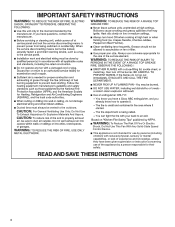
... lack of experience and knowledge, unless they have been given supervision or instruction concerning use of the appliance by a person responsible for their safety. To Reduce The Risk Of Fire Or Electric Shock, Do Not Use This Fan With Any Solid-State Speed Control Device. Do Not Use To Exhaust Hazardous Or Explosive Materials And Vapors. For General Ventilating Use Only.
... lack of experience and knowledge, unless they have been given supervision or instruction concerning use of the appliance by a person responsible for their safety. To Reduce The Risk Of Fire Or Electric Shock, Do Not Use This Fan With Any Solid-State Speed Control Device. Do Not Use To Exhaust Hazardous Or Explosive Materials And Vapors. For General Ventilating Use Only.
Installation Instructions
Page 5
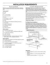
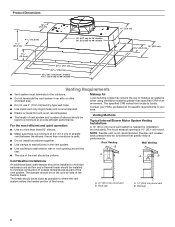
...; Metal snips ■ Phillips screwdriver Parts needed ■ Home power supply cable ■ 1 - 1/2" (13 mm) UL listed or CSA approved strain relief ■ 3 UL listed wire connectors ■ 1 wall or roof cap ■ Metal vent system ■ Blower motor system - Cabinet opening dimensions that all governing codes and ordinances. The hood liner must be away from electric cooking surfaces. See the "Electrical Requirements" section. Cabinet Dimensions 36" (91.4 cm) for 36" models 48" (121.9 cm) for...
...; Metal snips ■ Phillips screwdriver Parts needed ■ Home power supply cable ■ 1 - 1/2" (13 mm) UL listed or CSA approved strain relief ■ 3 UL listed wire connectors ■ 1 wall or roof cap ■ Metal vent system ■ Blower motor system - Cabinet opening dimensions that all governing codes and ordinances. The hood liner must be away from electric cooking surfaces. See the "Electrical Requirements" section. Cabinet Dimensions 36" (91.4 cm) for 36" models 48" (121.9 cm) for...

Installation Instructions
Page 6
... one elbow is used. ■ Do not install two elbows together. ■ Use clamps to seal all joints in your HVAC professional for installation (not included). Makeup Air Local building codes may require the use 4" (10.2 cm) laundry-type wall caps. ■ Use metal vent only. Venting Methods Typical Internal Blower Motor System Venting Installations A 10" (25.4 cm) round vent system is 10" (25.4 cm) round. Roof Venting Wall Venting B A A B Cold Weather Installations An additional back draft damper should be installed...
... one elbow is used. ■ Do not install two elbows together. ■ Use clamps to seal all joints in your HVAC professional for installation (not included). Makeup Air Local building codes may require the use 4" (10.2 cm) laundry-type wall caps. ■ Use metal vent only. Venting Methods Typical Internal Blower Motor System Venting Installations A 10" (25.4 cm) round vent system is 10" (25.4 cm) round. Roof Venting Wall Venting B A A B Cold Weather Installations An additional back draft damper should be installed...
Installation Instructions
Page 7
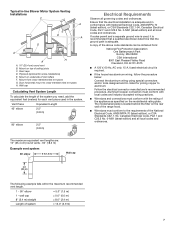
..., 15 A, fused electrical circuit is required. ■ If the house has aluminum wiring, follow the procedure below: Connect the aluminum wiring using special connectors and/or tools designed and UL listed for joining copper to the requirements of the system you need, add the equivalent feet (meters) for some installations) E. Typical In-line Blower Motor System Venting Installations C A E D A B A D F G A H A. 10" (25.4 cm) round vent B. Mount on top of system = 13.0" (3.9 m) 7 If codes permit...
..., 15 A, fused electrical circuit is required. ■ If the house has aluminum wiring, follow the procedure below: Connect the aluminum wiring using special connectors and/or tools designed and UL listed for joining copper to the requirements of the system you need, add the equivalent feet (meters) for some installations) E. Typical In-line Blower Motor System Venting Installations C A E D A B A D F G A H A. 10" (25.4 cm) round vent B. Mount on top of system = 13.0" (3.9 m) 7 If codes permit...

Installation Instructions
Page 8
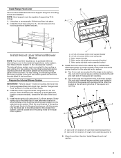
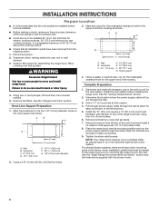
... cable through the wall. 3. Tighten the strain relief screws. Centerline C. 41/2" (11.4 cm) D. 13" (33.0 cm) E. 14" (35.5 cm) F. 28" (71.1 cm) G. Mark the locations for the four 1/8" (3 mm) diameter holes on the hood support as shown. ■ Before making cutouts, make sure there is proper clearance within the ceiling or wall for exhaust vent. ■ Hood liner is installed. 3. Remove terminal box cover and set aside. 7. See the "Install Range Hood Internal Blower Motor...
... cable through the wall. 3. Tighten the strain relief screws. Centerline C. 41/2" (11.4 cm) D. 13" (33.0 cm) E. 14" (35.5 cm) F. 28" (71.1 cm) G. Mark the locations for the four 1/8" (3 mm) diameter holes on the hood support as shown. ■ Before making cutouts, make sure there is proper clearance within the ceiling or wall for exhaust vent. ■ Hood liner is installed. 3. Remove terminal box cover and set aside. 7. See the "Install Range Hood Internal Blower Motor...
Installation Instructions
Page 9
... are required for the single motor system. Use the outside back (alternate location on some models) of the hood liner at the left and right end of the square vent opening . Motor spring clip (dual motor assembly location) 4. Clip nuts into place. See the "Install Range Hood Liner" section. 9 Install Range Hood Liner B The hood liner attaches to the hood support and tighten securely. See "Blower Motor System" in the Use and Care Guide. 2. Remove grease filters from hood liner. Install the motor support bracket using two 4.2 x 8 mm screws. Install motor...
... are required for the single motor system. Use the outside back (alternate location on some models) of the hood liner at the left and right end of the square vent opening . Motor spring clip (dual motor assembly location) 4. Clip nuts into place. See the "Install Range Hood Liner" section. 9 Install Range Hood Liner B The hood liner attaches to the hood support and tighten securely. See "Blower Motor System" in the Use and Care Guide. 2. Remove grease filters from hood liner. Install the motor support bracket using two 4.2 x 8 mm screws. Install motor...
Installation Instructions
Page 11
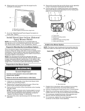
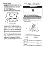
... blower motor assembly. Prepare for Mounting the In-Line Blower System The in -line blower housing and set them aside. 3. Plywood may be removed. D A. Blower mounting screws C. Bottom housing mounting holes E. Outlet Side A A A A Inlet Side A A A. A B 5. Remove the blower motor assembly from the range hood to the in -line blower system must be fastened to a secure structure of the blower must be used to mount the inline blower system to the structure. Wiring box connector B. Go to the "Make Electrical Power...
... blower motor assembly. Prepare for Mounting the In-Line Blower System The in -line blower housing and set them aside. 3. Plywood may be removed. D A. Blower mounting screws C. Bottom housing mounting holes E. Outlet Side A A A A Inlet Side A A A. A B 5. Remove the blower motor assembly from the range hood to the in -line blower system must be fastened to a secure structure of the blower must be used to mount the inline blower system to the structure. Wiring box connector B. Go to the "Make Electrical Power...

Installation Instructions
Page 12
... terminal box. Disconnect power. 2. UL Listed wire connectors C. White wires E. Green (or yellow/green) and green/yellow wires I A. Remove the terminal box covers and set the covers and screws aside. Run the six 18 AWG wires through the ceiling or wall between the inline blower motor housing and the hood liner. UL Listed or CSA approved 1/2" (13 mm) wiring conduit B. Determine and make the wiring connections. 8. Pull enough 1/2" (13 mm) wiring conduit to allow for the vent system. Motor electrical...
... terminal box. Disconnect power. 2. UL Listed wire connectors C. White wires E. Green (or yellow/green) and green/yellow wires I A. Remove the terminal box covers and set the covers and screws aside. Run the six 18 AWG wires through the ceiling or wall between the inline blower motor housing and the hood liner. UL Listed or CSA approved 1/2" (13 mm) wiring conduit B. Determine and make the wiring connections. 8. Pull enough 1/2" (13 mm) wiring conduit to allow for the vent system. Motor electrical...
Installation Instructions
Page 13
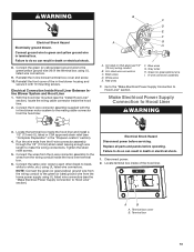
...cable connector inside the hood liner and install a 1/2" (13 mm) UL listed or CSA approved strain relief (see "Complete Preparation" in the terminal box using UL listed wire connectors. Terminal box 13 Reinstall the front cover of the hood liner. B C D E F A G H A. Red wires I . 6-wire connector assembly 7. Replace all parts and panels before servicing. Locate terminal box inside the hood liner terminal box. 6. Make Electrical Power Supply Connection to Hood Liner" section. Tighten the strain relief screws. 5. Connect the wires from the 6-wire connector assembly...
...cable connector inside the hood liner and install a 1/2" (13 mm) UL listed or CSA approved strain relief (see "Complete Preparation" in the terminal box using UL listed wire connectors. Terminal box 13 Reinstall the front cover of the hood liner. B C D E F A G H A. Red wires I . 6-wire connector assembly 7. Replace all parts and panels before servicing. Locate terminal box inside the hood liner terminal box. 6. Make Electrical Power Supply Connection to Hood Liner" section. Tighten the strain relief screws. 5. Connect the wires from the 6-wire connector assembly...
Installation Instructions
Page 14
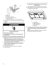
... your new hood liner, read the "Range Hood Use" section. NOTE: When using UL listed wire connectors. 6. See A the "Range Hood Use" section. Use UL listed wire connectors and connect white wires (A) together. A E D A A. Install terminal box cover. 7. Black wires C. WARNING Electrical Shock Hazard Electrically ground blower. Reconnect power. 14 B A BC A C D F A. Blower control switches D. Complete Installation and Check E Operation 1. Install grease filters. See the "Range Hood Care" section. 2. UL listed wire connectors D. Green, bare...
... your new hood liner, read the "Range Hood Use" section. NOTE: When using UL listed wire connectors. 6. See A the "Range Hood Use" section. Use UL listed wire connectors and connect white wires (A) together. A E D A A. Install terminal box cover. 7. Black wires C. WARNING Electrical Shock Hazard Electrically ground blower. Reconnect power. 14 B A BC A C D F A. Blower control switches D. Complete Installation and Check E Operation 1. Install grease filters. See the "Range Hood Care" section. 2. UL listed wire connectors D. Green, bare...
Installation Instructions
Page 18
... Blower Motor System above a cooktop with any problems or questions, call the KitchenAid Customer eXperience Center at : KitchenAid Brand Home Appliances Customer eXperience Center 200 - 6750 Century Ave. Order Model Number UXB1200DYS 600 CFM In-Line Blower Motor System - This information will fit right and work right because they are trained to fulfill the product warranty and provide after -warranty service anywhere in your appliance. Accessories Stainless Steel Grease Filter...
... Blower Motor System above a cooktop with any problems or questions, call the KitchenAid Customer eXperience Center at : KitchenAid Brand Home Appliances Customer eXperience Center 200 - 6750 Century Ave. Order Model Number UXB1200DYS 600 CFM In-Line Blower Motor System - This information will fit right and work right because they are trained to fulfill the product warranty and provide after -warranty service anywhere in your appliance. Accessories Stainless Steel Grease Filter...

Owners Manual
Page 4
To Reduce The Risk Of Fire Or Electric Shock, Do Not Use This Fan With Any Solid-State Speed Control Device. READ AND SAVE THESE INSTRUCTIONS 4 For General Ventilating Use Only. This appliance is not intended for use by persons (including children) with reduced physical, sensory or ... of experience and knowledge, unless they have been given supervision or instruction concerning use of the appliance by a person responsible for their safety. IMPORTANT SAFETY INSTRUCTIONS Ducted fans must always be vented to the outdoors. Do Not Use To Exhaust Hazardous Or Explosive Materials And Vapors.
To Reduce The Risk Of Fire Or Electric Shock, Do Not Use This Fan With Any Solid-State Speed Control Device. READ AND SAVE THESE INSTRUCTIONS 4 For General Ventilating Use Only. This appliance is not intended for use by persons (including children) with reduced physical, sensory or ... of experience and knowledge, unless they have been given supervision or instruction concerning use of the appliance by a person responsible for their safety. IMPORTANT SAFETY INSTRUCTIONS Ducted fans must always be vented to the outdoors. Do Not Use To Exhaust Hazardous Or Explosive Materials And Vapors.

Owners Manual
Page 5
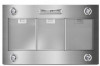
...; 3 metal grease filters ■ Hood liner with halogen lamps installed. ■ 1 - 10" (25.4 cm) square to comply with local codes. internal or external (see "Blower Motor System" in ceiling and wall where canopy hood will be installed must be sealed. Parts supplied Remove parts from strong draft areas, such as windows, doors, and strong heating vents. Minimum distance "X": 30" (76.2 cm) from electric cooking surfaces. The hood liner must be surrounded by a custom built enclosure with hood support capable...
...; 3 metal grease filters ■ Hood liner with halogen lamps installed. ■ 1 - 10" (25.4 cm) square to comply with local codes. internal or external (see "Blower Motor System" in ceiling and wall where canopy hood will be installed must be sealed. Parts supplied Remove parts from strong draft areas, such as windows, doors, and strong heating vents. Minimum distance "X": 30" (76.2 cm) from electric cooking surfaces. The hood liner must be surrounded by a custom built enclosure with hood support capable...
Owners Manual
Page 6
... in the vent system. ■ Use caulking to seal exterior wall or roof opening is not recommended. Wall cap 6 Consult your area. Rigid metal vent is recommended. ■ Plastic or metal foil vent is needed for specific requirements in your HVAC professional for installation (not included). Venting Methods Typical Internal Blower Motor System Venting Installations A 10" (25.4 cm) round vent system is not recommended. ■ The length of vent system and number of elbows should...
... in the vent system. ■ Use caulking to seal exterior wall or roof opening is not recommended. Wall cap 6 Consult your area. Rigid metal vent is recommended. ■ Plastic or metal foil vent is needed for specific requirements in your HVAC professional for installation (not included). Venting Methods Typical Internal Blower Motor System Venting Installations A 10" (25.4 cm) round vent system is not recommended. ■ The length of vent system and number of elbows should...

Owners Manual
Page 7
... 45° elbow Equivalent Length 2.5" (0.8 m) 90° elbow 2.5" (0.8 m) Electrical Requirements Observe all local codes and ordinances. Follow the electrical connector manufacturer's recommended procedure. Mount on the model/serial rating plate. Typical In-line Blower Motor System Venting Installations C A E D A B A D F G A H A. 10" (25.4 cm) round vent B. Plywood (optional for each vent piece used , it is recommended that a qualified electrician determine that the electrical installation is located behind the filter on top of the range hood. ■ Wire sizes must...
... 45° elbow Equivalent Length 2.5" (0.8 m) 90° elbow 2.5" (0.8 m) Electrical Requirements Observe all local codes and ordinances. Follow the electrical connector manufacturer's recommended procedure. Mount on the model/serial rating plate. Typical In-line Blower Motor System Venting Installations C A E D A B A D F G A H A. 10" (25.4 cm) round vent B. Plywood (optional for each vent piece used , it is recommended that a qualified electrician determine that the electrical installation is located behind the filter on top of the range hood. ■ Wire sizes must...
Owners Manual
Page 8
..." (25.4 cm) round vent transition with the blower motor. 2. Place the range hood near its mounting position and run through the strain relief into terminal box (enough to use: roof or wall exhaust. 3. Determine which venting method to make all installation parts have been removed from the top of the range hood liner using four 4.2 x 8 mm screws. 6. Determine the location where the power supply cable will be run the power supply cable through the wall. 3. INSTALLATION INSTRUCTIONS Prepare Location ■...
..." (25.4 cm) round vent transition with the blower motor. 2. Place the range hood near its mounting position and run through the strain relief into terminal box (enough to use: roof or wall exhaust. 3. Determine which venting method to make all installation parts have been removed from the top of the range hood liner using four 4.2 x 8 mm screws. 6. Determine the location where the power supply cable will be run the power supply cable through the wall. 3. INSTALLATION INSTRUCTIONS Prepare Location ■...

Owners Manual
Page 11
... Use two or more people, move and install in -line blower motor housing to release the blower motor assembly. Failure to do not want to remove the blower motor assembly, proceed to support the weight of the in -line blower system (50 lb [22.6 kg] minimum). Remove the front cover of the in -line blower motor housing and set them aside. 3. Spring clip D. Mounting holes 1. Install Hood Liner In-Line (External Type) Blower Motor NOTE: Your hood liner requires...
... Use two or more people, move and install in -line blower motor housing to release the blower motor assembly. Failure to do not want to remove the blower motor assembly, proceed to support the weight of the in -line blower system (50 lb [22.6 kg] minimum). Remove the front cover of the in -line blower motor housing and set them aside. 3. Spring clip D. Mounting holes 1. Install Hood Liner In-Line (External Type) Blower Motor NOTE: Your hood liner requires...
Owners Manual
Page 12
... "Install Hood Liner" section), run the 1/2" (13 mm) wiring conduit between the in-line blower and the hood liner. 3. Connect the vent system to the in -line blower system and seal all necessary cuts for In-Line Blower Motor System WARNING Electrical Shock Hazard Disconnect power before operating. Disconnect power. 2. Blue wires G. Use UL listed wire connectors and connect the blue wires (F) together. 7. Drill a 11/4" (3.2 cm) hole at this location. 4. Replace all parts and panels before servicing. Electrical terminal box...
... "Install Hood Liner" section), run the 1/2" (13 mm) wiring conduit between the in-line blower and the hood liner. 3. Connect the vent system to the in -line blower system and seal all necessary cuts for In-Line Blower Motor System WARNING Electrical Shock Hazard Disconnect power before operating. Disconnect power. 2. Blue wires G. Use UL listed wire connectors and connect the blue wires (F) together. 7. Drill a 11/4" (3.2 cm) hole at this location. 4. Replace all parts and panels before servicing. Electrical terminal box...

Owners Manual
Page 14
... Hazard Electrically ground blower. Blower control switches D. Install grease filters. Use UL listed wire connectors and connect black wires (B) together. 4. Use UL listed wire connectors and connect white wires (A) together. Halogen light switch C. Grease filter handle E. If the range hood does not operate, check to green and yellow ground wire in their sockets. 8. NOTE: When using UL listed wire connectors. 6. Connect ground wire to see whether a circuit breaker has tripped or a household fuse has blown. Disconnect power supply and check that all light bulbs...
... Hazard Electrically ground blower. Blower control switches D. Install grease filters. Use UL listed wire connectors and connect black wires (B) together. 4. Use UL listed wire connectors and connect white wires (A) together. Halogen light switch C. Grease filter handle E. If the range hood does not operate, check to green and yellow ground wire in their sockets. 8. NOTE: When using UL listed wire connectors. 6. Connect ground wire to see whether a circuit breaker has tripped or a household fuse has blown. Disconnect power supply and check that all light bulbs...

Owners Manual
Page 18
... the product warranty and provide after -warranty service anywhere in your correspondence. ■ Use and maintenance procedures. ■ Accessory and repair parts sales. ■ Specialized customer assistance (Spanish speaking, hearing impaired, limited vision, etc.). If you need replacement parts If you have any questions or concerns at 1-800-807-6777. Order Model Number UXB1200DYS 600 CFM In-Line Blower Motor System - Accessories Stainless Steel Grease Filter - kit contains one filter Order Part Number W10351855...
... the product warranty and provide after -warranty service anywhere in your correspondence. ■ Use and maintenance procedures. ■ Accessory and repair parts sales. ■ Specialized customer assistance (Spanish speaking, hearing impaired, limited vision, etc.). If you need replacement parts If you have any questions or concerns at 1-800-807-6777. Order Model Number UXB1200DYS 600 CFM In-Line Blower Motor System - Accessories Stainless Steel Grease Filter - kit contains one filter Order Part Number W10351855...


