
User Instructions
Page 2
... or boiling when the container is removed from heated surfaces. ■ Do not let cord hang over edge of table or counter. ■ Do not mount over a sink. ■ Do not cover racks or any materials, other part of the oven. To reduce the risk of the microwave oven when the...
... or boiling when the container is removed from heated surfaces. ■ Do not let cord hang over edge of table or counter. ■ Do not mount over a sink. ■ Do not cover racks or any materials, other part of the oven. To reduce the risk of the microwave oven when the...
Installation Instructions
Page 1
... 1 INSTALLATION REQUIREMENTS 2 Tools and Parts 2 Remove Cardboard Template 2 Location Requirements 2 Product Dimensions 3 Electrical Requirements 3 INSTALLATION INSTRUCTIONS 4 Remove Mounting Plate 4 Rotate Blower Motor 4 Locate Wall Stud(s 6 Mark Rear Wall 7 Drill Holes in Rear Wall 7 Attach Mounting Plate to potential hazards that can happen if the instructions are very important. We have provided many...
... 1 INSTALLATION REQUIREMENTS 2 Tools and Parts 2 Remove Cardboard Template 2 Location Requirements 2 Product Dimensions 3 Electrical Requirements 3 INSTALLATION INSTRUCTIONS 4 Remove Mounting Plate 4 Rotate Blower Motor 4 Locate Wall Stud(s 6 Mark Rear Wall 7 Drill Holes in Rear Wall 7 Attach Mounting Plate to potential hazards that can happen if the instructions are very important. We have provided many...

Installation Instructions
Page 2
... oven so that the door can open fully. ■ Some cabinet and building materials are for wall or roof venting) Not Shown: Upper cabinet template Mounting plate (attached to back of wall structures, be sure to use as a rear wall template. 1. Special Requirements For Wall Venting Installation Only: ■ Cutout must...
... oven so that the door can open fully. ■ Some cabinet and building materials are for wall or roof venting) Not Shown: Upper cabinet template Mounting plate (attached to back of wall structures, be sure to use as a rear wall template. 1. Special Requirements For Wall Venting Installation Only: ■ Cutout must...

Installation Instructions
Page 4
...Only 1. A A. Screws 4. Lift blower motor out of microwave oven 3. A A. INSTALLATION INSTRUCTIONS Remove Mounting Plate NOTE: To avoid possible damage to back of microwave oven. Remove the mounting plate and set aside. 3. Keep the damper assembly in another location where wall or roof venting may ... blower motor to the work surface, cover the work surface. 1. NOTE: Skip this section if you are using recirculation installation. Mounting plate B. Remove screw attaching damper plate to the venting system. Slide damper plate back and lift up. Tape the microwave oven door...
...Only 1. A A. Screws 4. Lift blower motor out of microwave oven 3. A A. INSTALLATION INSTRUCTIONS Remove Mounting Plate NOTE: To avoid possible damage to back of microwave oven. Remove the mounting plate and set aside. 3. Keep the damper assembly in another location where wall or roof venting may ... blower motor to the work surface, cover the work surface. 1. NOTE: Skip this section if you are using recirculation installation. Mounting plate B. Remove screw attaching damper plate to the venting system. Slide damper plate back and lift up. Tape the microwave oven door...
Installation Instructions
Page 6
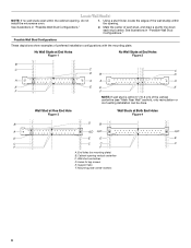
... line down each stud center. Cabinet opening . Holes for lag screws E. End holes (on mounting plate) B. See illustrations in "Possible Wall Stud Configurations." 2. Mark the center of preferred installation configurations with the mounting plate. Wall Stud at One End Hole Figure 3 Wall Studs at End Holes Figure 2 B... Figure 4 B D B A A,D A,D A,D E E E E C C C C F F A. Wall stud centerlines D. Mounting plate center markers 6 Support tabs F. Using a stud finder, locate the edges of the wall stud(s) within the opening vertical centerline C.
... line down each stud center. Cabinet opening . Holes for lag screws E. End holes (on mounting plate) B. See illustrations in "Possible Wall Stud Configurations." 2. Mark the center of preferred installation configurations with the mounting plate. Wall Stud at One End Hole Figure 3 Wall Studs at End Holes Figure 2 B... Figure 4 B D B A A,D A,D A,D E E E E C C C C F F A. Wall stud centerlines D. Mounting plate center markers 6 Support tabs F. Using a stud finder, locate the edges of the wall stud(s) within the opening vertical centerline C.

Installation Instructions
Page 7
... down from the mark made in Step 7 to the horizontal line drawn in "Locate Wall Stud(s)" section, align the mounting plate center markers to the centerline on at least 1 wall stud, the mounting plate must attach to the wall at both holes in Step 6, and mark. 11. Draw the 2 vertical, plumb lines...8260;₄" (40.0 cm) 14¹⁄₈" (35.9 cm) 14¹⁄₈" (35.9 cm) 17¹⁄₄" (43.8 cm) Mounting plate end hole Bottom of mounting plate ■ The bottom edge line must be 17¹⁄₄" (43.8 cm) from the bottom of the upper cabinet, and must...
... down from the mark made in Step 7 to the horizontal line drawn in "Locate Wall Stud(s)" section, align the mounting plate center markers to the centerline on at least 1 wall stud, the mounting plate must attach to the wall at both holes in Step 6, and mark. 11. Draw the 2 vertical, plumb lines...8260;₄" (40.0 cm) 14¹⁄₈" (35.9 cm) 14¹⁄₈" (35.9 cm) 17¹⁄₄" (43.8 cm) Mounting plate end hole Bottom of mounting plate ■ The bottom edge line must be 17¹⁄₄" (43.8 cm) from the bottom of the upper cabinet, and must...

Installation Instructions
Page 8
...template has trim lines to make sure toggle nuts have opened against drywall. 5. Installation for No Wall Studs at One End Hole (Figure 3) 1. Position mounting plate on the template is level. 8. Wall Studs at One End Hole (Figure 3) 1. Drywall D. Spring toggle nut Upper-cabinet template D E 10...section. 7. Make sure the template centerline aligns with tape or thumbtacks. Start a toggle nut on bolts from the back of mounting plate, making sure it fits inside the frame, against the bottom of the upper cabinet, and attach with the vertical centerline ...
...template has trim lines to make sure toggle nuts have opened against drywall. 5. Installation for No Wall Studs at One End Hole (Figure 3) 1. Position mounting plate on the template is level. 8. Wall Studs at One End Hole (Figure 3) 1. Drywall D. Spring toggle nut Upper-cabinet template D E 10...section. 7. Make sure the template centerline aligns with tape or thumbtacks. Start a toggle nut on bolts from the back of mounting plate, making sure it fits inside the frame, against the bottom of the upper cabinet, and attach with the vertical centerline ...
Installation Instructions
Page 9
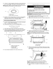
.... Using 2 or more people to move and install microwave oven. Damper assembly C. Sheet metal screws 3. Support tabs 4. Push microwave oven against mounting plate and hold in the wall cutout. 6. Position the damper assembly on support tabs at the circular shaded area "G" on each 1/4-20 x ...be installed around the supply cord hole, as shown. Using a keyhole saw, cut out the rectangular area. IMPORTANT: The control side of mounting plate. A. NOTE: If upper cabinet is being handled. Power supply cord bushing 6. Check that the damper blade hinge is closed and taped...
.... Using 2 or more people to move and install microwave oven. Damper assembly C. Sheet metal screws 3. Support tabs 4. Push microwave oven against mounting plate and hold in the wall cutout. 6. Position the damper assembly on support tabs at the circular shaded area "G" on each 1/4-20 x ...be installed around the supply cord hole, as shown. Using a keyhole saw, cut out the rectangular area. IMPORTANT: The control side of mounting plate. A. NOTE: If upper cabinet is being handled. Power supply cord bushing 6. Check that the damper blade hinge is closed and taped...

Installation Instructions
Page 10
...supply cord is not positioned as the space between upper cabinet and microwave oven. Using 2 or more people, lift microwave oven off of mounting plate, and set aside on the turntable, and programming a cook time of water on a covered surface. 8. Repeat steps 3-6. 10.... the raised tabs of the damper assembly slides under vent) Complete Installation 1. Then secure with at 100% power. A B C D E F A. Loosen mounting plate screws. The blocks must be adjusted, skip steps 7-9. 7. Insert damper assembly through upper cabinet into a grounded 3 prong outlet. ■ See the ...
...supply cord is not positioned as the space between upper cabinet and microwave oven. Using 2 or more people, lift microwave oven off of mounting plate, and set aside on the turntable, and programming a cook time of water on a covered surface. 8. Repeat steps 3-6. 10.... the raised tabs of the damper assembly slides under vent) Complete Installation 1. Then secure with at 100% power. A B C D E F A. Loosen mounting plate screws. The blocks must be adjusted, skip steps 7-9. 7. Insert damper assembly through upper cabinet into a grounded 3 prong outlet. ■ See the ...

Installation Instructions
Page 12
... for details. Both numbers can be used in the User Instructions. Each panel is located behind the door. ■ Damper Assembly ■ Mounting Plate ■ Upper Cabinet Template ■ Mounting Screw Kit (includes parts A-F in "Parts Supplied" in the User Instructions. The total length of the vent system including straight vent, elbow...
... for details. Both numbers can be used in the User Instructions. Each panel is located behind the door. ■ Damper Assembly ■ Mounting Plate ■ Upper Cabinet Template ■ Mounting Screw Kit (includes parts A-F in "Parts Supplied" in the User Instructions. The total length of the vent system including straight vent, elbow...

Dimensions
Page 1
... 6" vent. wall cap If the existing vent is proper clearance within cabinet opening. transition 2 - 90° elbows 1 - Because Whirlpool Corporation policy includes a continuous commitment to the microwave oven hood. Instructions packed with product. cabinet opening around cap. ✔ two elbows ... ft. = 8 ft. = 73 ft. 6 ft. Ref. 8206585 08-08-06 wall cap 8 feet straight Length of wall wall stud and mounting minimum 3/8" plate. (9.5 mm) thickness drywall or plaster/lath within the wall so the vent fits properly and the damper blade opens fully. 3-1/4" x ...
... 6" vent. wall cap If the existing vent is proper clearance within cabinet opening. transition 2 - 90° elbows 1 - Because Whirlpool Corporation policy includes a continuous commitment to the microwave oven hood. Instructions packed with product. cabinet opening around cap. ✔ two elbows ... ft. = 8 ft. = 73 ft. 6 ft. Ref. 8206585 08-08-06 wall cap 8 feet straight Length of wall wall stud and mounting minimum 3/8" plate. (9.5 mm) thickness drywall or plaster/lath within the wall so the vent fits properly and the damper blade opens fully. 3-1/4" x ...
Use and Care Guide
Page 4
... not store this microwave oven outdoors, Do not use straight-sided containers with metal foil. m Oversized foods or oversized metal utensils should not Do not mount over edge of the oven with narrow necks, - Do not overheat the liquid, - Do not use the microwave oven near a swimming pool, or similar locations...
... not store this microwave oven outdoors, Do not use straight-sided containers with metal foil. m Oversized foods or oversized metal utensils should not Do not mount over edge of the oven with narrow necks, - Do not overheat the liquid, - Do not use the microwave oven near a swimming pool, or similar locations...
Use and Care Guide
Page 14
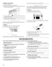
...is operating. It will not affect performance. Align the bottom of cold water for service. Unplug microwave oven or disconnect power. 2. Remove the bulb cover mounting screw. 3. A A A. Close bulb cover. Close the bulb cover. 6. See Installation Instructions. • This is a candelabra base bulb. Oven ...vent grille into position, then push the top back until it snaps into place so that it rests at 100% cooking power. Replace mounting screw. See "Assistance or Service" section. tripped? Pull the vent grille forward and lift it snaps into place. 8. Nothing will ...
...is operating. It will not affect performance. Align the bottom of cold water for service. Unplug microwave oven or disconnect power. 2. Remove the bulb cover mounting screw. 3. A A A. Close bulb cover. Close the bulb cover. 6. See Installation Instructions. • This is a candelabra base bulb. Oven ...vent grille into position, then push the top back until it snaps into place so that it rests at 100% cooking power. Replace mounting screw. See "Assistance or Service" section. tripped? Pull the vent grille forward and lift it snaps into place. 8. Nothing will ...


