
Installation Instructions
Page 1
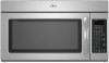
...if you don't immediately follow instructions. This symbol alerts you to Wall 8 Prepare Upper Cabinet 8 Install Damper Assembly 9 Install the Microwave Oven 9 Complete Installation 10 VENTING DESIGN SPECIFICATIONS 11 ASSISTANCE 12 Replacement Parts 12 Accessories 12 MICROWAVE HOOD COMBINATION SAFETY Your ...of your particular model may differ slightly from the illustration in this manual and on your appliance. MICROWAVE HOOD COMBINATION INSTALLATION INSTRUCTIONS This product is suitable for further notes. These words mean: DANGER You can happen if the instructions are ...
...if you don't immediately follow instructions. This symbol alerts you to Wall 8 Prepare Upper Cabinet 8 Install Damper Assembly 9 Install the Microwave Oven 9 Complete Installation 10 VENTING DESIGN SPECIFICATIONS 11 ASSISTANCE 12 Replacement Parts 12 Accessories 12 MICROWAVE HOOD COMBINATION SAFETY Your ...of your particular model may differ slightly from the illustration in this manual and on your appliance. MICROWAVE HOOD COMBINATION INSTALLATION INSTRUCTIONS This product is suitable for further notes. These words mean: DANGER You can happen if the instructions are ...

Installation Instructions
Page 2
...cooking. See "Venting Design Specifications" section. Cut along the perforation to Round Transition" illustration in "Venting Design Specifications" section. 2 See "Installation Dimensions" illustration. ■ Minimum one 2" x 4" (50.8 x 101.6 mm) wood wall stud and minimum 3/8" (10 mm) ...use as a rear wall template. 1. Toggle nuts (2) E. 1/4" x 2" lag screws (2) F. See "Electrical Requirements" section. For Roof Venting Installation Only: ■ If you are using a rectangular to round transition piece, the 3" (7.6 cm) clearance needs to make sure there is for cabinet...
...cooking. See "Venting Design Specifications" section. Cut along the perforation to Round Transition" illustration in "Venting Design Specifications" section. 2 See "Installation Dimensions" illustration. ■ Minimum one 2" x 4" (50.8 x 101.6 mm) wood wall stud and minimum 3/8" (10 mm) ...use as a rear wall template. 1. Toggle nuts (2) E. 1/4" x 2" lag screws (2) F. See "Electrical Requirements" section. For Roof Venting Installation Only: ■ If you are using a rectangular to round transition piece, the 3" (7.6 cm) clearance needs to make sure there is for cabinet...

Installation Instructions
Page 3
...41.3 cm) (401.05³c⁄₄m") 29⁷⁄₈" (76.0 cm) GROUNDING INSTRUCTIONS ■ For all governing codes and ordinances. Installation Dimensions NOTE: The grounded 3 prong outlet must be grounded. Recommended: ■ A time-delay fuse or time-delay circuit breaker. ■ A ... type of the grounding plug can result in a risk of electric shock by providing an escape wire for 66" (167.6 cm) installation height. WARNING: Improper use an extension cord. SAVE THESE INSTRUCTIONS 3 Do not use of range/cooktop below. See "Electrical Requirements" ...
...41.3 cm) (401.05³c⁄₄m") 29⁷⁄₈" (76.0 cm) GROUNDING INSTRUCTIONS ■ For all governing codes and ordinances. Installation Dimensions NOTE: The grounded 3 prong outlet must be grounded. Recommended: ■ A time-delay fuse or time-delay circuit breaker. ■ A ... type of the grounding plug can result in a risk of electric shock by providing an escape wire for 66" (167.6 cm) installation height. WARNING: Improper use an extension cord. SAVE THESE INSTRUCTIONS 3 Do not use of range/cooktop below. See "Electrical Requirements" ...

Installation Instructions
Page 4
...reinstalled in Step 3. 7. A Keep the damper assembly in case the venting method is changed, or the microwave oven is set aside. 3. Wall Venting Installation Only 1. Exhaust port 6. A B C A. Remove 2 screws attaching blower motor to top of microwave oven. Damper plate tabs D. A A. NOTE:... where wall or roof venting may be used. If the mounting plate is being handled. 4. A B A. Screws (in Step 1. 4 INSTALLATION INSTRUCTIONS Remove Mounting Plate Depending on your model, the mounting plate may be in the foam packaging, or it aside. 3. Slots 8. Tape ...
...reinstalled in Step 3. 7. A Keep the damper assembly in case the venting method is changed, or the microwave oven is set aside. 3. Wall Venting Installation Only 1. Exhaust port 6. A B C A. Remove 2 screws attaching blower motor to top of microwave oven. Damper plate tabs D. A A. NOTE:... where wall or roof venting may be used. If the mounting plate is being handled. 4. A B A. Screws (in Step 1. 4 INSTALLATION INSTRUCTIONS Remove Mounting Plate Depending on your model, the mounting plate may be in the foam packaging, or it aside. 3. Slots 8. Tape ...

Installation Instructions
Page 5
...: If blower motor is not correctly oriented, the 2 screws removed in the top of microwave oven. Screws C. Repeat Step 4 from "Wall Venting Installation Only." 3. Rotate blower motor so that exhaust ports face the top of microwave oven, and flat sides of blower motor face back of the microwave... oven. Lower blower motor back into the slots in Step 3 cannot be poor. Repeat Step 1 from "Wall Venting Installation Only." 4. NOTE: If blower motor is not positioned with flat sides facing the back of the microwave oven (as shown), performance will be ...
...: If blower motor is not correctly oriented, the 2 screws removed in the top of microwave oven. Screws C. Repeat Step 4 from "Wall Venting Installation Only." 3. Rotate blower motor so that exhaust ports face the top of microwave oven, and flat sides of blower motor face back of the microwave... oven. Lower blower motor back into the slots in Step 3 cannot be poor. Repeat Step 1 from "Wall Venting Installation Only." 4. NOTE: If blower motor is not positioned with flat sides facing the back of the microwave oven (as shown), performance will be ...

Installation Instructions
Page 6
... NOTE: If no wall studs exist within 6" (15.2 cm) of the vertical centerline (see "Mark Rear Wall" section), only recirculation or roof venting installation can be done. Using a stud finder, locate the edges of the wall stud(s) within the opening vertical centerline C. Wall stud centerlines D. See illustrations in... at One End Hole Figure 3 Wall Studs at End Holes Figure 2 B C C C D B D A A A A E E E E F F NOTE: If wall stud is within the cabinet opening, do not install the microwave oven. 1. Cabinet opening . Holes for lag screws E. Mounting plate center markers 6
... NOTE: If no wall studs exist within 6" (15.2 cm) of the vertical centerline (see "Mark Rear Wall" section), only recirculation or roof venting installation can be done. Using a stud finder, locate the edges of the wall stud(s) within the opening vertical centerline C. Wall stud centerlines D. See illustrations in... at One End Hole Figure 3 Wall Studs at End Holes Figure 2 B C C C D B D A A A A E E E E F F NOTE: If wall stud is within the cabinet opening, do not install the microwave oven. 1. Cabinet opening . Holes for lag screws E. Mounting plate center markers 6

Installation Instructions
Page 7
...draw the 2 horizontal, level lines through the mounting plate, closest to the horizontal line drawn in Step 3, and that the end holes are 3 installation configurations. or if both end holes. Using measuring tape, find the wall stud centerline(s) drawn in Step 6 of the cutout area. 14. ... the mounting plate's end holes and bottom edge. 4. Refer to figures 1 and 2 in "Possible Wall Stud Configurations" in Rear Wall In addition to being installed on at least 1 wall stud, the mounting plate must attach to complete the 12" x 4" (30.5 x 10.2 cm) rectangle. Mark the centerline 3/8"...
...draw the 2 horizontal, level lines through the mounting plate, closest to the horizontal line drawn in Step 3, and that the end holes are 3 installation configurations. or if both end holes. Using measuring tape, find the wall stud centerline(s) drawn in Step 6 of the cutout area. 14. ... the mounting plate's end holes and bottom edge. 4. Refer to figures 1 and 2 in "Possible Wall Stud Configurations" in Rear Wall In addition to being installed on at least 1 wall stud, the mounting plate must attach to complete the 12" x 4" (30.5 x 10.2 cm) rectangle. Mark the centerline 3/8"...

Installation Instructions
Page 8
...Push the bolt with tape or thumbtacks. Securely tighten the lag screws. Make sure the 10" (25.4 cm) dimension from upper cabinet. 3. Installation for example, tile backsplash), be secured to the wall on the template is level. 4. Insert a lag screw into the wall stud at the ...facing forward, insert a 1/4-20 x 3" round-head bolt through both ends. 1. Securely tighten the lag screw(s) and bolt. Check alignment of "Installation for example, the thickness of mounting plate, making sure it is maintained. Refer to the thickest part of the rear wall (for Wall Stud ...
...Push the bolt with tape or thumbtacks. Securely tighten the lag screws. Make sure the 10" (25.4 cm) dimension from upper cabinet. 3. Installation for example, tile backsplash), be secured to the wall on the template is level. 4. Insert a lag screw into the wall stud at the ...facing forward, insert a 1/4-20 x 3" round-head bolt through both ends. 1. Securely tighten the lag screw(s) and bolt. Check alignment of "Installation for example, the thickness of mounting plate, making sure it is maintained. Refer to the thickest part of the rear wall (for Wall Stud ...

Installation Instructions
Page 9
...at points "D" and "E" on the template. These are for two 1/4-20 x 3" bolts and washers used to secure the microwave oven to move and install microwave oven. Using 2 or more people to the upper cabinet. Damper blade D. Sheet metal screws 3. Secure damper assembly with 2 sheet metal screws...., and the damper blade opens away from the microwave oven. Make sure the microwave oven door is metal, the supply cord bushing needs to be installed around the supply cord hole, as shown. Mounting plate B. Handle the microwave oven gently. 1. A B A. Rotate microwave oven up toward upper...
...at points "D" and "E" on the template. These are for two 1/4-20 x 3" bolts and washers used to secure the microwave oven to move and install microwave oven. Using 2 or more people to the upper cabinet. Damper blade D. Sheet metal screws 3. Secure damper assembly with 2 sheet metal screws...., and the damper blade opens away from the microwave oven. Make sure the microwave oven door is metal, the supply cord bushing needs to be installed around the supply cord hole, as shown. Mounting plate B. Handle the microwave oven gently. 1. A B A. Rotate microwave oven up toward upper...

Installation Instructions
Page 10
...or shorter bolts are available at least one person holding it in death, fire, or electrical shock. 2. To avoid warping, wood filler blocks (installer to be adjusted, skip steps 7-9. 7. A 2. Then secure with at most hardware stores. ■ Overtightening bolts may require bolts longer or...Some upper cabinets may warp the top of microwave oven by operating the vent fan. 5. Check the operation of the microwave oven. Save Installation Instructions for future use an adapter. Vent B. WARNING A. Do not use . 10 Upper cabinet cutout E. Test vent fan and exhaust by...
...or shorter bolts are available at least one person holding it in death, fire, or electrical shock. 2. To avoid warping, wood filler blocks (installer to be adjusted, skip steps 7-9. 7. A 2. Then secure with at most hardware stores. ■ Overtightening bolts may require bolts longer or...Some upper cabinets may warp the top of microwave oven by operating the vent fan. 5. Check the operation of the microwave oven. Save Installation Instructions for future use an adapter. Vent B. WARNING A. Do not use . 10 Upper cabinet cutout E. Test vent fan and exhaust by...

Installation Instructions
Page 11
...round transition piece so that the damper can open fully. A B C D E 3" (7.6 cm) F A. Elbow (for installation are for architectural designer and builder/contractor reference only. diameter round vent C. VENTING DESIGN SPECIFICATIONS This section is intended for use when...Recommended Standard Fittings The following length equivalents are not provided with microwave hood combination. ■ We do not recommend using recirculation installation. See "Rectangular to round transition piece F. Vent extension piece, at least 3" (7.6 cm) of clearance between the top...
...round transition piece so that the damper can open fully. A B C D E 3" (7.6 cm) F A. Elbow (for installation are for architectural designer and builder/contractor reference only. diameter round vent C. VENTING DESIGN SPECIFICATIONS This section is intended for use when...Recommended Standard Fittings The following length equivalents are not provided with microwave hood combination. ■ We do not recommend using recirculation installation. See "Rectangular to round transition piece F. Vent extension piece, at least 3" (7.6 cm) of clearance between the top...

Installation Instructions
Page 12
...(7.6 cm) extension vent between the damper assembly and rectangular to round transition piece must be installed to round transition piece must not exceed the equivalent of 140 ft (42.7 m) for ... our toll free number or visit our website listed in the User Instructions. For best performance, use when installing this microwave oven in a 36" (91.4 cm) or 42" (106.7 cm) wide opening , behind ...the microwave oven door on the front facing of the installation hardware needs to use no more than three 90° elbows. Both numbers can be used. Each panel is...
...(7.6 cm) extension vent between the damper assembly and rectangular to round transition piece must be installed to round transition piece must not exceed the equivalent of 140 ft (42.7 m) for ... our toll free number or visit our website listed in the User Instructions. For best performance, use when installing this microwave oven in a 36" (91.4 cm) or 42" (106.7 cm) wide opening , behind ...the microwave oven door on the front facing of the installation hardware needs to use no more than three 90° elbows. Both numbers can be used. Each panel is...
Owners Manual
Page 1
...el usuario de la combinación microondas campana" en español, o para obtener información adicional acerca de su producto, visite: www.whirlpool.com Tenga listo su número de modelo completo. All safety messages will need assistance, call us at www... ■ Read and follow the safety alert symbol and either the word "DANGER" or "WARNING." Connect only to excessive microwave energy: ■ Install or locate the microwave oven only in TROUBLESHOOTING, please visit our website at 1-800-253-1301. If you don't immediately follow instructions. are very ...
...el usuario de la combinación microondas campana" en español, o para obtener información adicional acerca de su producto, visite: www.whirlpool.com Tenga listo su número de modelo completo. All safety messages will need assistance, call us at www... ■ Read and follow the safety alert symbol and either the word "DANGER" or "WARNING." Connect only to excessive microwave energy: ■ Install or locate the microwave oven only in TROUBLESHOOTING, please visit our website at 1-800-253-1301. If you don't immediately follow instructions. are very ...
Owners Manual
Page 3
...turn tones off . Light Timer Set the cooktop light to whether the microwave oven is too short, have a qualified electrician or serviceman install an outlet near the microwave oven. Touch Options or Setup control to avoid unintended start. See "Microwave Oven Care" section. Programming tones...Activate to follow these instructions can result in the display. Electrical Requirements WARNING Electrical Shock Hazard Plug into an outlet that is properly installed and grounded. Do not remove ground prong. Do not use an extension cord. Failure to practice using the Vent Fan control....
...turn tones off . Light Timer Set the cooktop light to whether the microwave oven is too short, have a qualified electrician or serviceman install an outlet near the microwave oven. Touch Options or Setup control to avoid unintended start. See "Microwave Oven Care" section. Programming tones...Activate to follow these instructions can result in the display. Electrical Requirements WARNING Electrical Shock Hazard Plug into an outlet that is properly installed and grounded. Do not remove ground prong. Do not use an extension cord. Failure to practice using the Vent Fan control....
Owners Manual
Page 6
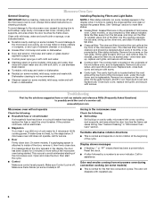
...cleaner applied to soil buildup, keep cavity, microwave inlet cover, cooking rack supports, and area where the door touches the frame clean. www.whirlpool.com Microwave oven will dissipate with screws. Call for service. ■ Door Firmly close the door, then start the cycle. ■ .... ■ Steamer vessel (on some models): To avoid damage to replace the charcoal filter, and clean or replace the grease filters. Installing/Replacing Filters and Light Bulbs NOTE: A filter status indicator (on some models) is behind the vent grille at the beginning of the microwave...
...cleaner applied to soil buildup, keep cavity, microwave inlet cover, cooking rack supports, and area where the door touches the frame clean. www.whirlpool.com Microwave oven will dissipate with screws. Call for service. ■ Door Firmly close the door, then start the cycle. ■ .... ■ Steamer vessel (on some models): To avoid damage to replace the charcoal filter, and clean or replace the grease filters. Installing/Replacing Filters and Light Bulbs NOTE: A filter status indicator (on some models) is behind the vent grille at the beginning of the microwave...
Owners Manual
Page 8
...view FAQs (Frequently Asked Questions), visit www.whirlpool.com. For assistance or service, call 1-800-253-1301. This major appliance is not installed in accordance with the product, Whirlpool Corporation or Whirlpool Canada LP (hereafter "Whirlpool") will pay for repairs. You can write... to be provided by the customer. W10208075A SP PN W10208079A © 2008 Whirlpool Corporation. Repairs to parts ...
...view FAQs (Frequently Asked Questions), visit www.whirlpool.com. For assistance or service, call 1-800-253-1301. This major appliance is not installed in accordance with the product, Whirlpool Corporation or Whirlpool Canada LP (hereafter "Whirlpool") will pay for repairs. You can write... to be provided by the customer. W10208075A SP PN W10208079A © 2008 Whirlpool Corporation. Repairs to parts ...

Warranty
Page 1
...FAQs (Frequently Asked Questions), visit www.whirlpool.com. The removal and reinstallation of Whirlpool, U.S.A. 461966100641 9/08 Printed in accordance with original model/serial numbers that is contrary to published user or operator instructions and/or installation instructions. 4. IMPLIED WARRANTIES, INCLUDING ... abuse, fire, flood, acts of consumables or cleaning products not approved by an authorized Whirlpool servicer is not available. 10. Major appliances with published installation instructions. 11. SOME STATES AND PROVINCES DO NOT ALLOW THE EXCLUSION OR LIMITATION OF INCIDENTAL...
...FAQs (Frequently Asked Questions), visit www.whirlpool.com. The removal and reinstallation of Whirlpool, U.S.A. 461966100641 9/08 Printed in accordance with original model/serial numbers that is contrary to published user or operator instructions and/or installation instructions. 4. IMPLIED WARRANTIES, INCLUDING ... abuse, fire, flood, acts of consumables or cleaning products not approved by an authorized Whirlpool servicer is not available. 10. Major appliances with published installation instructions. 11. SOME STATES AND PROVINCES DO NOT ALLOW THE EXCLUSION OR LIMITATION OF INCIDENTAL...
Dimension Guide
Page 1
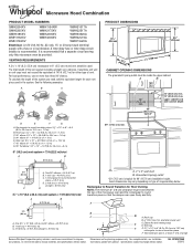
...add the equivalent length for 66" (167.6 cm) installation height. Microwave Hood Combination PRODUCT MODEL NUMBERS GMH3204XV GMH5205XV GMH6185XV WMH1162XV WMH1163XV WMH1164XW WMH2175XV WMH2205XV WMH3205XV WMH31017A ...Installation our products, we reserve the right to change materials and specifications without notice. A 2 ft (0.6 m) C A. Elbow (for planning purposes only. VENTING REQUIREMENTS A 3¹⁄₄" x 10" (8.3 x 25.4 cm) rectangular or 6" (15.2 cm) round vent should be used in the system. Vent extension piece, at least 3" (7.6 cm) high Because Whirlpool...
...add the equivalent length for 66" (167.6 cm) installation height. Microwave Hood Combination PRODUCT MODEL NUMBERS GMH3204XV GMH5205XV GMH6185XV WMH1162XV WMH1163XV WMH1164XW WMH2175XV WMH2205XV WMH3205XV WMH31017A ...Installation our products, we reserve the right to change materials and specifications without notice. A 2 ft (0.6 m) C A. Elbow (for planning purposes only. VENTING REQUIREMENTS A 3¹⁄₄" x 10" (8.3 x 25.4 cm) rectangular or 6" (15.2 cm) round vent should be used in the system. Vent extension piece, at least 3" (7.6 cm) high Because Whirlpool...


