Owners Manual
Page 1
You will need assistance, call us at www.whirlpool.com for purchasing this high-quality product. Puede encontrar su número de modelo y ...Cleaning Cycle 11 SteamClean 11 General Cleaning 12 Oven Light 12 TROUBLESHOOTING 13 ACCESSORIES 14 WARRANTY 16 W10200354B ® ELECTRIC RANGE USER INSTRUCTIONS THANK YOU for additional information. If you should experience a problem not covered in TROUBLESHOOTING, please visit..." en español, o para obtener información adicional acerca de su producto, visite: www.whirlpool.com Tenga listo su número de modelo completo.
You will need assistance, call us at www.whirlpool.com for purchasing this high-quality product. Puede encontrar su número de modelo y ...Cleaning Cycle 11 SteamClean 11 General Cleaning 12 Oven Light 12 TROUBLESHOOTING 13 ACCESSORIES 14 WARRANTY 16 W10200354B ® ELECTRIC RANGE USER INSTRUCTIONS THANK YOU for additional information. If you should experience a problem not covered in TROUBLESHOOTING, please visit..." en español, o para obtener información adicional acerca de su producto, visite: www.whirlpool.com Tenga listo su número de modelo completo.
Owners Manual
Page 3
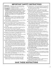
...; Do Not Clean Door Gasket - IMPORTANT SAFETY INSTRUCTIONS WARNING: To reduce the risk of fire, electrical shock, injury to persons, or damage when using the range. ■ User Servicing - They should never be stored in Manual. ■ Before Self-Cleaning the Oven - Smother fire or flame ... of these liners may result in desired location while oven is in cabinets above a range or on hot surfaces may result in injury. ■ Keep Oven Vent Ducts Unobstructed. ■ Placement of electric shock. To reduce the risk of burns, ignition of flammable materials, and spillage due...
...; Do Not Clean Door Gasket - IMPORTANT SAFETY INSTRUCTIONS WARNING: To reduce the risk of fire, electrical shock, injury to persons, or damage when using the range. ■ User Servicing - They should never be stored in Manual. ■ Before Self-Cleaning the Oven - Smother fire or flame ... of these liners may result in desired location while oven is in cabinets above a range or on hot surfaces may result in injury. ■ Keep Oven Vent Ducts Unobstructed. ■ Placement of electric shock. To reduce the risk of burns, ignition of flammable materials, and spillage due...

Dimension Guide
Page 1
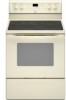
... screwed all the way in the "Product Dimensions" section. upper cabinet depth B. 30" (76.2 cm) min. Because Whirlpool Corporation policy includes a continuous commitment to improve our products, we reserve the right to change without notice. Ref. 30" (76 cm) Freestanding Electric Range PRODUCT MODEL NUMBERS GFE461LV GFE471LV WFE301LV WFE361LV WFE364LV WFE366LV WFE371LV WFE374LV WFE381LV WFE114LW...
... screwed all the way in the "Product Dimensions" section. upper cabinet depth B. 30" (76.2 cm) min. Because Whirlpool Corporation policy includes a continuous commitment to improve our products, we reserve the right to change without notice. Ref. 30" (76 cm) Freestanding Electric Range PRODUCT MODEL NUMBERS GFE461LV GFE471LV WFE301LV WFE361LV WFE364LV WFE366LV WFE371LV WFE374LV WFE381LV WFE114LW...

Installation Instructions
Page 1
U.S.A. Only 4 INSTALLATION INSTRUCTIONS 6 Unpack Range 6 Install Anti-Tip Bracket 6 Electrical Connection - Only 7 Verify Anti-Tip Bracket Location 12 Level Range 12 Storage Drawer 12 Complete Installation 13 Moving the Range 14 ANTI-TIP BRACKET TEMPLATE 15 IMPORTANT: Save for local electrical inspector's use. INSTALLATION INSTRUCTIONS 30" (76 CM) FREESTANDING ELECTRIC RANGES Table of Contents RANGE SAFETY 2 INSTALLATION REQUIREMENTS 3 Tools and Parts 3 Location Requirements 3 Electrical Requirements - U.S.A. W10252706B
U.S.A. Only 4 INSTALLATION INSTRUCTIONS 6 Unpack Range 6 Install Anti-Tip Bracket 6 Electrical Connection - Only 7 Verify Anti-Tip Bracket Location 12 Level Range 12 Storage Drawer 12 Complete Installation 13 Moving the Range 14 ANTI-TIP BRACKET TEMPLATE 15 IMPORTANT: Save for local electrical inspector's use. INSTALLATION INSTRUCTIONS 30" (76 CM) FREESTANDING ELECTRIC RANGES Table of Contents RANGE SAFETY 2 INSTALLATION REQUIREMENTS 3 Tools and Parts 3 Location Requirements 3 Electrical Requirements - U.S.A. W10252706B

Installation Instructions
Page 3
...and Safety Standard, Title 24 CFR, Part 3280 (formerly the Federal Standard for convenient use with the range, see "Install Anti-Tip Bracket" section. ■ Grounded electrical supply is marked for use the Standard for use in a mobile home installation. To install the ... be secured to subfloor. Thickness of this range is to make sure that all parts are shown must be revised. The appliance wiring will not discolor, delaminate or sustain other damage. Check existing electrical supply. See "Electrical Connection" section. 3 INSTALLATION REQUIREMENTS Tools and ...
...and Safety Standard, Title 24 CFR, Part 3280 (formerly the Federal Standard for convenient use with the range, see "Install Anti-Tip Bracket" section. ■ Grounded electrical supply is marked for use the Standard for use in a mobile home installation. To install the ... be secured to subfloor. Thickness of this range is to make sure that all parts are shown must be revised. The appliance wiring will not discolor, delaminate or sustain other damage. Check existing electrical supply. See "Electrical Connection" section. 3 INSTALLATION REQUIREMENTS Tools and ...

Installation Instructions
Page 4
...from: National Fire Protection Association One Batterymarch Park Quincy, MA 02269. A freestanding range may be installed next to 22" (55.9 cm) from floor F 2.2 cm) min. upper cabinet depth B. 30" (76.2 cm) min. D. 30¹⁄₈" (76.5 cm) min. WARNING: Improper connection of the... B A F B C D E F E D A. 27 69.9 cm) max. Cabinet Dimensions Cabinet opening dimensions shown are adequate and in conformance with the National Electrical Code, ANSI/ NFPA 70-latest edition and all the way in a risk of an uncovered wood or metal cabinet. required between cutout and cabinet door...
...from: National Fire Protection Association One Batterymarch Park Quincy, MA 02269. A freestanding range may be installed next to 22" (55.9 cm) from floor F 2.2 cm) min. upper cabinet depth B. 30" (76.2 cm) min. D. 30¹⁄₈" (76.5 cm) min. WARNING: Improper connection of the... B A F B C D E F E D A. 27 69.9 cm) max. Cabinet Dimensions Cabinet opening dimensions shown are adequate and in conformance with the National Electrical Code, ANSI/ NFPA 70-latest edition and all the way in a risk of an uncovered wood or metal cabinet. required between cutout and cabinet door...

Installation Instructions
Page 5
...power supply cord enters the appliance. or 50-amp, range power supply cord (pigtail) must be connected to the neutral by a white cover. Electrical Connection To properly install your range, you must determine the type of electrical connection you will be using and follow the instructions ...provided for it here. ■ Range must be used , a matching UL listed, 4-wire, 250-volt...
...power supply cord enters the appliance. or 50-amp, range power supply cord (pigtail) must be connected to the neutral by a white cover. Electrical Connection To properly install your range, you must determine the type of electrical connection you will be using and follow the instructions ...provided for it here. ■ Range must be used , a matching UL listed, 4-wire, 250-volt...

Installation Instructions
Page 7
... the back of the terminal block. Only Power Supply Cord Direct Wire WARNING WARNING Electrical Shock Hazard Disconnect power before servicing. Electrical Shock Hazard Disconnect power before servicing. A B C A. Remove plastic tag holding three 10-32 hex nuts from range. 3. Electrically ground range. U.S.A. Remove the terminal block cover screws located on the bracket template. Terminal block...
... the back of the terminal block. Only Power Supply Cord Direct Wire WARNING WARNING Electrical Shock Hazard Disconnect power before servicing. Electrical Shock Hazard Disconnect power before servicing. A B C A. Remove plastic tag holding three 10-32 hex nuts from range. 3. Electrically ground range. U.S.A. Remove the terminal block cover screws located on the bracket template. Terminal block...

Installation Instructions
Page 8
...the neutral 1. Discard C. 4. Ground-link screw 2. Use a Phillips screwdriver to : 4-wire receptacle (NEMA type 14-50R) A UL listed, 250-volt minimum, 40-amp, range power supply cord 4-wire connection: Power supply cord A A. A B A. Removable retaining nut B. Add strain relief. Concuit ■ Tighten strain relief screw against the power supply.... ■ Assemble a UL listed conduit connector in the opening . A B C 5. Metal ground strap B. Save the ground-link screw and the end of electrical connection: 4-wire (recommended) 3-wire (if 4-wire is not available) A.
...the neutral 1. Discard C. 4. Ground-link screw 2. Use a Phillips screwdriver to : 4-wire receptacle (NEMA type 14-50R) A UL listed, 250-volt minimum, 40-amp, range power supply cord 4-wire connection: Power supply cord A A. A B A. Removable retaining nut B. Add strain relief. Concuit ■ Tighten strain relief screw against the power supply.... ■ Assemble a UL listed conduit connector in the opening . A B C 5. Metal ground strap B. Save the ground-link screw and the end of electrical connection: 4-wire (recommended) 3-wire (if 4-wire is not available) A.

Installation Instructions
Page 10
... wire must be attached first and must be connected directly to the terminal block. A A B B C A. Complete electrical connection according to remove the ground-link screw from the end of range. Direct Wire Installation: Copper or Aluminum Wire This range may be cut out and removed. Loosen (do not remove) the setscrew on bottom of...
... wire must be attached first and must be connected directly to the terminal block. A A B B C A. Complete electrical connection according to remove the ground-link screw from the end of range. Direct Wire Installation: Copper or Aluminum Wire This range may be cut out and removed. Loosen (do not remove) the setscrew on bottom of...

Installation Instructions
Page 13
...and oven. Turn on . 8. When the range has been on range operation. Complete Installation 1. See "Level Range." 5. Read "Range Use" in the drawer glides. If range is fully engaged on both sides, slide the drawer back into an outlet. ■ Electrical supply is level. Engage drawer glide. 4. NOTE...: When you have all packaging materials. 4. For more information, read the "Range Care" section of the storage drawer and place it inside the range in the Use and Care Guide. See...
...and oven. Turn on . 8. When the range has been on range operation. Complete Installation 1. See "Level Range." 5. Read "Range Use" in the drawer glides. If range is fully engaged on both sides, slide the drawer back into an outlet. ■ Electrical supply is level. Engage drawer glide. 4. NOTE...: When you have all packaging materials. 4. For more information, read the "Range Care" section of the storage drawer and place it inside the range in the Use and Care Guide. See...

Installation Instructions
Page 14
...follow these instructions can result in death or electrical shock. 1. Check that range is under anti-tip bracket. Check that range is under anti-tip bracket. 5. Disconnect power. 2. If removing the range is moved. Slide range forward. 3. Check that anti-tip bracket is... installed: ■ Look for cleaning or maintenance: For power supply cord-connected ranges: 1. Failure to floor. ■ Slide range back so rear range foot is level. 14 Electrical Shock Hazard Disconnect power before operating. Complete cleaning or maintenance. 4. Unplug the power supply ...
...follow these instructions can result in death or electrical shock. 1. Check that range is under anti-tip bracket. Check that range is under anti-tip bracket. 5. Disconnect power. 2. If removing the range is moved. Slide range forward. 3. Check that anti-tip bracket is... installed: ■ Look for cleaning or maintenance: For power supply cord-connected ranges: 1. Failure to floor. ■ Slide range back so rear range foot is level. 14 Electrical Shock Hazard Disconnect power before operating. Complete cleaning or maintenance. 4. Unplug the power supply ...


