Owners Manual
Page 1
...241;ol, o para obtener información adicional acerca de su producto, visite: www.whirlpool.com Tenga listo su número de modelo completo. Table of Contents RANGE SAFETY 2 The Anti-Tip Bracket 2 FEATURE GUIDE 4 COOKTOP USE 6 OVEN USE 7...Light 12 TROUBLESHOOTING 13 ACCESSORIES 14 WARRANTY 16 W10200354B You will need assistance, call us at www.whirlpool.com for purchasing this high-quality product. Puede encontrar su número de modelo y de serie... oven frame behind the storage drawer panel. ® ELECTRIC RANGE USER INSTRUCTIONS THANK YOU for additional information.
...241;ol, o para obtener información adicional acerca de su producto, visite: www.whirlpool.com Tenga listo su número de modelo completo. Table of Contents RANGE SAFETY 2 The Anti-Tip Bracket 2 FEATURE GUIDE 4 COOKTOP USE 6 OVEN USE 7...Light 12 TROUBLESHOOTING 13 ACCESSORIES 14 WARRANTY 16 W10200354B You will need assistance, call us at www.whirlpool.com for purchasing this high-quality product. Puede encontrar su número de modelo y de serie... oven frame behind the storage drawer panel. ® ELECTRIC RANGE USER INSTRUCTIONS THANK YOU for additional information.
Owners Manual
Page 3
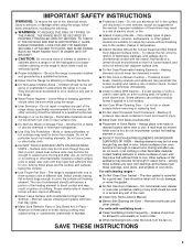
... - Flammable materials should never be stored in an oven or near surface units may penetrate the broken cooktop and create a risk of electric shock. Do not use . Heating elements should not be immersed in injury. ■ Keep Oven Vent Ducts Unobstructed. ■ Placement...Self-Cleaning the Oven - IMPORTANT SAFETY INSTRUCTIONS WARNING: To reduce the risk of fire, electrical shock, injury to persons, or damage when using the range. ■ User Servicing - children climbing on the backguard of electric shock, or fire. ■ Glazed Cooking Utensils - If a wet sponge or cloth ...
... - Flammable materials should never be stored in an oven or near surface units may penetrate the broken cooktop and create a risk of electric shock. Do not use . Heating elements should not be immersed in injury. ■ Keep Oven Vent Ducts Unobstructed. ■ Placement...Self-Cleaning the Oven - IMPORTANT SAFETY INSTRUCTIONS WARNING: To reduce the risk of fire, electrical shock, injury to persons, or damage when using the range. ■ User Servicing - children climbing on the backguard of electric shock, or fire. ■ Glazed Cooking Utensils - If a wet sponge or cloth ...

Dimension Guide
Page 1
...and the bottom of cooktop, see Installation Instructions packed with ranges. 30" (76 cm) Freestanding Electric Range PRODUCT MODEL NUMBERS GFE461LV GFE471LV WFE301LV WFE361LV WFE364LV WFE366LV WFE371LV WFE374LV WFE381LV ...30" (76.2 cm) min. D. 30¹⁄₈" (76.5 cm) min. from either cabinet, 5¹⁄₂" (14.0 cm) max. Because Whirlpool Corporation policy includes a continuous commitment to improve our products, we reserve the right to the proper electrical voltage and frequency as specified on the oven frame behind storage drawer panel) *Range...
...and the bottom of cooktop, see Installation Instructions packed with ranges. 30" (76 cm) Freestanding Electric Range PRODUCT MODEL NUMBERS GFE461LV GFE471LV WFE301LV WFE361LV WFE364LV WFE366LV WFE371LV WFE374LV WFE381LV ...30" (76.2 cm) min. D. 30¹⁄₈" (76.5 cm) min. from either cabinet, 5¹⁄₂" (14.0 cm) max. Because Whirlpool Corporation policy includes a continuous commitment to improve our products, we reserve the right to the proper electrical voltage and frequency as specified on the oven frame behind storage drawer panel) *Range...

Installation Instructions
Page 1
Only 4 INSTALLATION INSTRUCTIONS 6 Unpack Range 6 Install Anti-Tip Bracket 6 Electrical Connection - W10252706B Only 7 Verify Anti-Tip Bracket Location 12 Level Range 12 Storage Drawer 12 Complete Installation 13 Moving the Range 14 ANTI-TIP BRACKET TEMPLATE 15 IMPORTANT: Save for local electrical inspector's use. U.S.A. U.S.A. INSTALLATION INSTRUCTIONS 30" (76 CM) FREESTANDING ELECTRIC RANGES Table of Contents RANGE SAFETY 2 INSTALLATION REQUIREMENTS 3 Tools and Parts 3 Location Requirements 3 Electrical Requirements -
Only 4 INSTALLATION INSTRUCTIONS 6 Unpack Range 6 Install Anti-Tip Bracket 6 Electrical Connection - W10252706B Only 7 Verify Anti-Tip Bracket Location 12 Level Range 12 Storage Drawer 12 Complete Installation 13 Moving the Range 14 ANTI-TIP BRACKET TEMPLATE 15 IMPORTANT: Save for local electrical inspector's use. U.S.A. U.S.A. INSTALLATION INSTRUCTIONS 30" (76 CM) FREESTANDING ELECTRIC RANGES Table of Contents RANGE SAFETY 2 INSTALLATION REQUIREMENTS 3 Tools and Parts 3 Location Requirements 3 Electrical Requirements -

Installation Instructions
Page 3
...;₈" (3.5 cm) diameter connection opening dimensions that are shown must be used. See "Electrical Requirements" section. If cabinet storage is not applicable, use the Standard for convenient use with ranges. When such standard is to terminal block) ■ 3 - Tools needed If using ... terminals with installation clearances specified on the left side frame behind the storage drawer panel. ■ The range should be installed. Check existing electrical supply. Location Requirements IMPORTANT: Observe all governing codes and ordinances. ■ It is located on the ...
...;₈" (3.5 cm) diameter connection opening dimensions that are shown must be used. See "Electrical Requirements" section. If cabinet storage is not applicable, use the Standard for convenient use with ranges. When such standard is to terminal block) ■ 3 - Tools needed If using ... terminals with installation clearances specified on the left side frame behind the storage drawer panel. ■ The range should be installed. Check existing electrical supply. Location Requirements IMPORTANT: Observe all governing codes and ordinances. ■ It is located on the ...

Installation Instructions
Page 4
... depth and 36" (91.4 cm) countertop height. WARNING: Improper connection of electric shock. Model/serial rating plate (located on the left side frame behind storage drawer panel) *Range can be obtained from: National Fire Protection Association One Batterymarch Park Quincy, MA 02269. D. 30¹⁄₈" (76.5 cm) min. A copy of cooktop, see...
... depth and 36" (91.4 cm) countertop height. WARNING: Improper connection of electric shock. Model/serial rating plate (located on the left side frame behind storage drawer panel) *Range can be obtained from: National Fire Protection Association One Batterymarch Park Quincy, MA 02269. D. 30¹⁄₈" (76.5 cm) min. A copy of cooktop, see...

Installation Instructions
Page 5
... 40- or 50-amp power supply cord (pigtail) (see following Range Rating chart). For 50-amp rated cord kits, use kits that the range can be at the point the power supply cord enters the appliance. See "Electrical Connection." Connectors on the supply end. This cord contains 4 copper...or green/yellow cover and the neutral conductor by a link. Electrical Connection To properly install your range, you must determine the type of electrical connection you will be using and follow the instructions provided for it here. ■ Range must be revised so the green ground wire of the 4-...
... 40- or 50-amp power supply cord (pigtail) (see following Range Rating chart). For 50-amp rated cord kits, use kits that the range can be at the point the power supply cord enters the appliance. See "Electrical Connection." Connectors on the supply end. This cord contains 4 copper...or green/yellow cover and the neutral conductor by a link. Electrical Connection To properly install your range, you must determine the type of electrical connection you will be using and follow the instructions provided for it here. ■ Range must be revised so the green ground wire of the 4-...

Installation Instructions
Page 7
... Power Supply Cord Direct Wire WARNING WARNING Electrical Shock Hazard Disconnect power before servicing. Electrical Shock Hazard Disconnect power before servicing. Electrically ground range. A B C A. Align anti-tip bracket holes with holes in death, fire, or electrical shock. Tap plastic anchors into a grounded...or ceramic floor, use a 4.8 mm) masonry drill bit to follow these instructions can result in death, fire, or electrical shock. 1. Electrical Connection - Use a new 40 amp power supply cord. Failure to remove cover from floor. 6. Disconnect power. 2. ...
... Power Supply Cord Direct Wire WARNING WARNING Electrical Shock Hazard Disconnect power before servicing. Electrical Shock Hazard Disconnect power before servicing. Electrically ground range. A B C A. Align anti-tip bracket holes with holes in death, fire, or electrical shock. Tap plastic anchors into a grounded...or ceramic floor, use a 4.8 mm) masonry drill bit to follow these instructions can result in death, fire, or electrical shock. 1. Electrical Connection - Use a new 40 amp power supply cord. Failure to remove cover from floor. 6. Disconnect power. 2. ...

Installation Instructions
Page 8
... be Go to Section: connecting to remove the ground-link screw from the back of the ground-link under the screw. 8 Part of electrical connection: 4-wire (recommended) 3-wire (if 4-wire is not available) A. UL listed strain relief ■ Tighten strain relief screw against ... Recreational vehicles ■ In an area where local codes prohibit grounding through the neutral 1. Save the ground-link screw and the end of the range. Style 1: Power supply cord strain relief ■ Remove the knockout for the flexible conduit connection. ■ Assemble a UL listed conduit connector in...
... be Go to Section: connecting to remove the ground-link screw from the back of the ground-link under the screw. 8 Part of electrical connection: 4-wire (recommended) 3-wire (if 4-wire is not available) A. UL listed strain relief ■ Tighten strain relief screw against ... Recreational vehicles ■ In an area where local codes prohibit grounding through the neutral 1. Save the ground-link screw and the end of the range. Style 1: Power supply cord strain relief ■ Remove the knockout for the flexible conduit connection. ■ Assemble a UL listed conduit connector in...

Installation Instructions
Page 10
...line 1 (black), neutral (white), and line 2 (red) wires. Ground-link screw C. Line 2 (red) wire F. Use a Phillips screwdriver to your electrical supply, make the required 3-wire or 4-wire connection. 1. Save the ground-link screw and the end of terminal lugs. C D E A. Direct Wire Installation...: Copper or Aluminum Wire This range may be cut out and removed. Strip outer covering back 3" (7.6 cm) to the fuse disconnect or circuit breaker box. Complete electrical connection according to remove the ground-link screw from the end of metal...
...line 1 (black), neutral (white), and line 2 (red) wires. Ground-link screw C. Line 2 (red) wire F. Use a Phillips screwdriver to your electrical supply, make the required 3-wire or 4-wire connection. 1. Save the ground-link screw and the end of terminal lugs. C D E A. Direct Wire Installation...: Copper or Aluminum Wire This range may be cut out and removed. Strip outer covering back 3" (7.6 cm) to the fuse disconnect or circuit breaker box. Complete electrical connection according to remove the ground-link screw from the end of metal...

Installation Instructions
Page 13
... of the storage drawer and place it inside the range in the drawer glides. Slowly push the storage drawer into an outlet. ■ Electrical supply is fully engaged on both sides, slide the drawer back into appropriate outlet. A A. Complete Installation 1. See "Level Range." 5. If range does not operate, check the following: ■ Household fuse...
... of the storage drawer and place it inside the range in the drawer glides. Slowly push the storage drawer into an outlet. ■ Electrical supply is fully engaged on both sides, slide the drawer back into appropriate outlet. A A. Complete Installation 1. See "Level Range." 5. If range does not operate, check the following: ■ Household fuse...

Installation Instructions
Page 14
... do so can result in power supply cord. 5. Failure to children and adults. Electrical Shock Hazard Disconnect power before operating. Disconnect power. 2. Check that range is level. 6. Check that range is level. 14 When moving range, slide range onto cardboard or hardboard to rear range foot. Slide range forward. 2. Replace all parts and panels before servicing. Slide...
... do so can result in power supply cord. 5. Failure to children and adults. Electrical Shock Hazard Disconnect power before operating. Disconnect power. 2. Check that range is level. 6. Check that range is level. 14 When moving range, slide range onto cardboard or hardboard to rear range foot. Slide range forward. 2. Replace all parts and panels before servicing. Slide...


