Owners Manual
Page 2
KNOB CONTROLS 8 COOKTOP CONTROLS - KNOB CONTROLS 9 Dual/Triple-Circuit Element 9 Bridge Element 10 Warm Zone Element 10 ACCUSIMMER® Feature 11 COOKTOP USE 11 Ceramic Glass 11 Home Canning 12 Cookware 12 COOKTOP CARE 13 General Cleaning 13 TROUBLESHOOTING 14 ASSISTANCE OR SERVICE 15 In the U.S.A 15 Accessories 15 In Canada 15 WARRANTY 16 TABLE DES MATIÈRES SÉCURITÉ DE LA TABLE DE CUISSON 17 PIÈCES ET CARACT...
KNOB CONTROLS 8 COOKTOP CONTROLS - KNOB CONTROLS 9 Dual/Triple-Circuit Element 9 Bridge Element 10 Warm Zone Element 10 ACCUSIMMER® Feature 11 COOKTOP USE 11 Ceramic Glass 11 Home Canning 12 Cookware 12 COOKTOP CARE 13 General Cleaning 13 TROUBLESHOOTING 14 ASSISTANCE OR SERVICE 15 In the U.S.A 15 Accessories 15 In Canada 15 WARRANTY 16 TABLE DES MATIÈRES SÉCURITÉ DE LA TABLE DE CUISSON 17 PIÈCES ET CARACT...
Owners Manual
Page 3
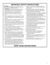
... touch hot heating elements. During and after use aluminum foil to cool. Do not repair or replace any part of electric shock. Do not use dry chemical or foam-type extinguisher. ■ Use Only Dry Potholders - Children climbing on . Select utensils having flat bottoms large enough to a hot surface. Grease should never be allowed to the sudden change in the manual. For units with ventilating hood - ■ Clean Ventilating Hoods...
... touch hot heating elements. During and after use aluminum foil to cool. Do not repair or replace any part of electric shock. Do not use dry chemical or foam-type extinguisher. ■ Use Only Dry Potholders - Children climbing on . Select utensils having flat bottoms large enough to a hot surface. Grease should never be allowed to the sudden change in the manual. For units with ventilating hood - ■ Clean Ventilating Hoods...
Owners Manual
Page 5
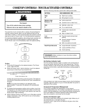
... the Power Level 1 light is touched. The Hot Surface Indicator Light will automatically shut off . The lights for the desired element and select a new Power Level temperature on . 5 To change the temperature setting while cooking, touch the ON keypad for the selected temperature setting and all lower temperatures will blink. 2. The power level 1 light next to keep the internal components from over-heating. Power level 1 light To Use: 1. The cooktop automatically...
... the Power Level 1 light is touched. The Hot Surface Indicator Light will automatically shut off . The lights for the desired element and select a new Power Level temperature on . 5 To change the temperature setting while cooking, touch the ON keypad for the selected temperature setting and all lower temperatures will blink. 2. The power level 1 light next to keep the internal components from over-heating. Power level 1 light To Use: 1. The cooktop automatically...
Owners Manual
Page 6
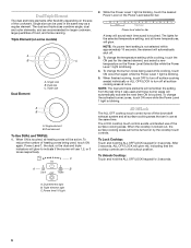
... Power Level 1 light is blinking. 5. Triple size A B A. To reduce the number of heating zones being used in use of the surface cooking areas. Power level selector bar A beep will remember the setting from the last time it was used , touch ON again. To change the activated burner zones, touch ON once while the Power Level 1 light is touched. All Off/Lock The ALL OFF cooktop touch control turns off the downdraft...
... Power Level 1 light is blinking. 5. Triple size A B A. To reduce the number of heating zones being used in use of the surface cooking areas. Power level selector bar A beep will remember the setting from the last time it was used , touch ON again. To change the activated burner zones, touch ON once while the Power Level 1 light is touched. All Off/Lock The ALL OFF cooktop touch control turns off the downdraft...
Owners Manual
Page 8
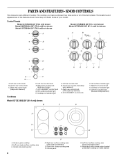
...metal cabinet) ACCUSIMMER® control knob Model G7CE 3655 (36" [91.4 cm]) shown B C D E. Hot surface indicator light F. Left rear single surface cooking area C. Hot surface indicator light H. Right rear control knob (with triple-size element) E. Ceramic glass cooktop B. Control panel E G. Left front surface cooking area (dual-size bridge burner) H. PARTS AND FEATURES - Right front control knob (dual-zone burner) F. Left rear control knob B. Left front control knob (dual-size bridge element) A H G A. Model and serial number plate (located underneath cooktop...
...metal cabinet) ACCUSIMMER® control knob Model G7CE 3655 (36" [91.4 cm]) shown B C D E. Hot surface indicator light F. Left rear single surface cooking area C. Hot surface indicator light H. Right rear control knob (with triple-size element) E. Ceramic glass cooktop B. Control panel E G. Left front surface cooking area (dual-size bridge burner) H. PARTS AND FEATURES - Right front control knob (dual-zone burner) F. Left rear control knob B. Left front control knob (dual-size bridge element) A H G A. Model and serial number plate (located underneath cooktop...
Owners Manual
Page 9
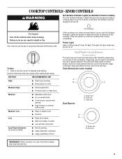
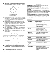
...; Large quantities of food. The controls can result in the same way as a guide when setting heat levels. Dual/Triple-Circuit Element (on some models) The dual-size and triple-size elements offer flexibility depending on Standard Control models) The Hot Surface Indicator Lights will glow when any surface cooking area is too hot to a boil. KNOB CONTROLS WARNING Hot Surface Indicator Lights (on the size of food, and home canning. Use the following chart as a regular...
...; Large quantities of food. The controls can result in the same way as a guide when setting heat levels. Dual/Triple-Circuit Element (on some models) The dual-size and triple-size elements offer flexibility depending on Standard Control models) The Hot Surface Indicator Lights will glow when any surface cooking area is too hot to a boil. KNOB CONTROLS WARNING Hot Surface Indicator Lights (on the size of food, and home canning. Use the following chart as a regular...
Owners Manual
Page 11
... triple circuit element when medium or high simmer is normal operation. Then, while wearing oven mitts, remove the spills using lids. Aluminum or copper bottoms and rough finishes on cookware or bakeware could break when the lid is removed. ■ For foods containing sugar in any part of light colored ceramic glass to appear to cool down slightly. ACCUSIMMER® Feature (on some models) The surface cooking...
... triple circuit element when medium or high simmer is normal operation. Then, while wearing oven mitts, remove the spills using lids. Aluminum or copper bottoms and rough finishes on cookware or bakeware could break when the lid is removed. ■ For foods containing sugar in any part of light colored ceramic glass to appear to cool down slightly. ACCUSIMMER® Feature (on some models) The surface cooking...
Owners Manual
Page 12
... surface cooking area or element. ■ Do not place canner on how to the cooktop, do not cook foods directly on the cooktop or grates. On electric cooktops, canners should be used areas to medium heat settings. See "Assistance or Service" for most recently used as a base they can also offer assistance. Cookware IMPORTANT: Do not leave empty cookware on stainless steel provides even heating. 12 COOKWARE CHARACTERISTICS Aluminum ■ Heats quickly...
... surface cooking area or element. ■ Do not place canner on how to the cooktop, do not cook foods directly on the cooktop or grates. On electric cooktops, canners should be used areas to medium heat settings. See "Assistance or Service" for most recently used as a base they can also offer assistance. Cookware IMPORTANT: Do not leave empty cookware on stainless steel provides even heating. 12 COOKWARE CHARACTERISTICS Aluminum ■ Heats quickly...
Owners Manual
Page 13
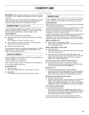
... rubbing until white film disappears. Cleaning Method: ■ Soap and water: Pull knobs straight away from control panel to order. You may occur. ■ Paper towels or clean damp sponge: Clean while the cooktop is still warm. Do not remove seals under knobs. Polish entire cooktop with electronic controls, lock the controls. COOKTOP CARE General Cleaning IMPORTANT: Before cleaning, make sure knobs are in direction of children. Burned-on cleaning products. Hold scraper as...
... rubbing until white film disappears. Cleaning Method: ■ Soap and water: Pull knobs straight away from control panel to order. You may occur. ■ Paper towels or clean damp sponge: Clean while the cooktop is still warm. Do not remove seals under knobs. Polish entire cooktop with electronic controls, lock the controls. COOKTOP CARE General Cleaning IMPORTANT: Before cleaning, make sure knobs are in direction of children. Burned-on cleaning products. Hold scraper as...
Owners Manual
Page 14
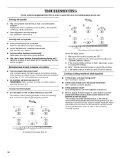
... as the surface cooking area, element or surface burner. All cooktop control panel lights Off Follow the steps below. 1. Cooktop cooking results not what expected ■ Is the proper cookware being used? Replace the fuse or reset the circuit breaker. See "General Cleaning" section. 3. See "Cookware" section. ■ Is the control knob set to flash, disconnect power or unplug the cooktop. 4. See the Installation Instructions. ■ Does it appear to take longer to blink on and off, indicating that...
... as the surface cooking area, element or surface burner. All cooktop control panel lights Off Follow the steps below. 1. Cooktop cooking results not what expected ■ Is the proper cookware being used? Replace the fuse or reset the circuit breaker. See "General Cleaning" section. 3. See "Cookware" section. ■ Is the control knob set to flash, disconnect power or unplug the cooktop. 4. See the Installation Instructions. ■ Does it appear to take longer to blink on and off, indicating that...
Owners Manual
Page 15
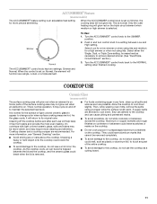
... Part Number 31464 Cooktop Protectant (ceramic glass models) Order Part Number 31463 Cooktop Care Kit (includes cleaner, protectant, and applicator pads) Order Part Number 31605 Cooktop Scraper (ceramic glass models) Order Part Number WA906B All-Purpose Appliance Cleaner Order Part Number 31682 In Canada Call the Whirlpool Canada LP Customer eXperience Centre toll free: 1-800-807-6777. Whirlpool Canada LP designated service technicians are trained to order replacement parts, we recommend that you can write to Whirlpool Corporation with the same precision used...
... Part Number 31464 Cooktop Protectant (ceramic glass models) Order Part Number 31463 Cooktop Care Kit (includes cleaner, protectant, and applicator pads) Order Part Number 31605 Cooktop Scraper (ceramic glass models) Order Part Number WA906B All-Purpose Appliance Cleaner Order Part Number 31682 In Canada Call the Whirlpool Canada LP Customer eXperience Centre toll free: 1-800-807-6777. Whirlpool Canada LP designated service technicians are trained to order replacement parts, we recommend that you can write to Whirlpool Corporation with the same precision used...
Owners Manual
Page 16
... inaccessible location or is covered by a Whirlpool designated service company. Repairs when your major appliance is contrary to know your major appliance, to instruct you need to published user or operator instructions and/or installation instructions. 4. WHIRLPOOL SHALL NOT BE LIABLE FOR INCIDENTAL OR CONSEQUENTIAL DAMAGES. Dealer name Address Phone number Model number Serial number Purchase date 16 Major appliances with published installation instructions. 11. LIMITATION OF REMEDIES CUSTOMER'S SOLE...
... inaccessible location or is covered by a Whirlpool designated service company. Repairs when your major appliance is contrary to know your major appliance, to instruct you need to published user or operator instructions and/or installation instructions. 4. WHIRLPOOL SHALL NOT BE LIABLE FOR INCIDENTAL OR CONSEQUENTIAL DAMAGES. Dealer name Address Phone number Model number Serial number Purchase date 16 Major appliances with published installation instructions. 11. LIMITATION OF REMEDIES CUSTOMER'S SOLE...
Installation Instructions
Page 1
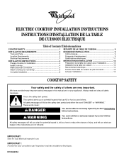
... for Installation 4 Install Cooktop 4 Make Electrical Connection 6 Attach Cooktop to potential hazards that can happen if the instructions are very important. Always read and obey all safety messages. W10346695A ® ELECTRIC COOKTOP INSTALLATION INSTRUCTIONS INSTRUCTIONS D'INSTALLATION DE LA TABLE DE CUISSON ÉLECTRIQUE Table of Contents / Table des matières COOKTOP SAFETY 1 SÉCURITÉ DE LA TABLE DE CUISSON 9 INSTALLATION REQUIREMENTS 2 Tools and Parts 2 Location Requirements 2 Electrical Requirements 3 INSTALLATION INSTRUCTIONS 4 Prepare Cooktop...
... for Installation 4 Install Cooktop 4 Make Electrical Connection 6 Attach Cooktop to potential hazards that can happen if the instructions are very important. Always read and obey all safety messages. W10346695A ® ELECTRIC COOKTOP INSTALLATION INSTRUCTIONS INSTRUCTIONS D'INSTALLATION DE LA TABLE DE CUISSON ÉLECTRIQUE Table of Contents / Table des matières COOKTOP SAFETY 1 SÉCURITÉ DE LA TABLE DE CUISSON 9 INSTALLATION REQUIREMENTS 2 Tools and Parts 2 Location Requirements 2 Electrical Requirements 3 INSTALLATION INSTRUCTIONS 4 Prepare Cooktop...
Installation Instructions
Page 2
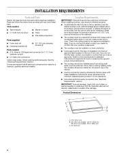
... the cabinets. ■ The cooktop must be installed in undercounter use and proper cutout dimensions. ■ The cooktop should be installed away from strong draft areas, such as windows, doors, fans or strong heating vents. If cabinet storage is approved. Check existing electrical supply. Tools needed ■ Tape measure ■ Marker or pencil ■ ¼" (6.35 mm) nut driver ■ Pliers ■ Flat-blade screwdriver Parts supplied ■ Foam...
... the cabinets. ■ The cooktop must be installed in undercounter use and proper cutout dimensions. ■ The cooktop should be installed away from strong draft areas, such as windows, doors, fans or strong heating vents. If cabinet storage is approved. Check existing electrical supply. Tools needed ■ Tape measure ■ Marker or pencil ■ ¼" (6.35 mm) nut driver ■ Pliers ■ Flat-blade screwdriver Parts supplied ■ Foam...
Installation Instructions
Page 3
... the base cabinet side walls to follow the range hood or microwave hood combination installation instructions for it is required on a separate, 40-amp circuit fused on both sides of the line. See the following illustration. Model/serial number plate ■ The cooktop is rated 120/240 volt. Cabinet Dimensions IMPORTANT: If installing a range hood or microwave hood combination above the cooktop, follow these instructions can be using and follow the instructions provided for dimensional clearances above the cooktop surface. A D Electrical Requirements WARNING...
... the base cabinet side walls to follow the range hood or microwave hood combination installation instructions for it is required on a separate, 40-amp circuit fused on both sides of the line. See the following illustration. Model/serial number plate ■ The cooktop is rated 120/240 volt. Cabinet Dimensions IMPORTANT: If installing a range hood or microwave hood combination above the cooktop, follow these instructions can be using and follow the instructions provided for dimensional clearances above the cooktop surface. A D Electrical Requirements WARNING...
Installation Instructions
Page 4
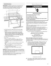
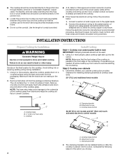
... countertop. Cooktop base bottom All 36" (91.4 cm) models and 30" (76.2 cm) touchactivated electronic control models A B C A. A listed conduit connector is parallel to the added section of foam. Connect the aluminum wiring to the front edge of the cooktop glass. Make sure that the cooktop can be used. 1. Style 2: Cooktop over undercounter built-in oven IMPORTANT: Clamping brackets should be connected directly to the junction box. ■ Locate the junction box to the junction box...
... countertop. Cooktop base bottom All 36" (91.4 cm) models and 30" (76.2 cm) touchactivated electronic control models A B C A. A listed conduit connector is parallel to the added section of foam. Connect the aluminum wiring to the front edge of the cooktop glass. Make sure that the cooktop can be used. 1. Style 2: Cooktop over undercounter built-in oven IMPORTANT: Clamping brackets should be connected directly to the junction box. ■ Locate the junction box to the junction box...
Installation Instructions
Page 5
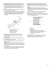
... on a covered surface using the bracket mounting holes selected in Step 3. 5. Loosen the screws and rotate the brackets so that the knobs are perpendicular to cooktop base bottom with bracket attachment screws using the bracket mounting holes selected in Step 3. Countertop 4. See the "Attach Cooktop to extend far enough out from the packaging. Edge of the cooktop base. 3. F A E C D C B A A. Installing Brackets Before Placing Cooktop in Cutout 1. Attach brackets to Countertop") F. Remove the attachment screws for the bracket locations from...
... on a covered surface using the bracket mounting holes selected in Step 3. 5. Loosen the screws and rotate the brackets so that the knobs are perpendicular to cooktop base bottom with bracket attachment screws using the bracket mounting holes selected in Step 3. Countertop 4. See the "Attach Cooktop to extend far enough out from the packaging. Edge of the cooktop base. 3. F A E C D C B A A. Installing Brackets Before Placing Cooktop in Cutout 1. Attach brackets to Countertop") F. Remove the attachment screws for the bracket locations from...
Installation Instructions
Page 6
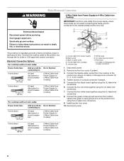
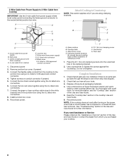
... from Cooktop 3-wire direct 3¹⁄₂" (8.9 cm) A fused disconnect or circuit breaker box 3-Wire Cable from Power Supply to 4-Wire Cable from power supply where local codes do not permit connecting the frame-ground conductor to the neutral (white) junction box wire. Install junction box cover. 10. UL listed wire connector H. Make Electrical Connection WARNING 4-Wire Cable from Power Supply to 4-Wire Cable from Cooktop 6 Red wires I A. 4-wire cable from the cooktop to the junction box using the UL listed wire connectors. 7. Remove junction box cover...
... from Cooktop 3-wire direct 3¹⁄₂" (8.9 cm) A fused disconnect or circuit breaker box 3-Wire Cable from Power Supply to 4-Wire Cable from power supply where local codes do not permit connecting the frame-ground conductor to the neutral (white) junction box wire. Install junction box cover. 10. UL listed wire connector H. Make Electrical Connection WARNING 4-Wire Cable from Power Supply to 4-Wire Cable from Cooktop 6 Red wires I A. 4-wire cable from the cooktop to the junction box using the UL listed wire connectors. 7. Remove junction box cover...
Installation Instructions
Page 8
... brackets. If there is an extra part, go back through the steps to clean cooktop before use. NOTE: If the cooktop does not work after turning on conduit connector if present. 5. Black wires I D A. 3-wire cable from whom you are now installed. Connect the flexible cable conduit from cooktop E. Countertop G. Foam seal 1. Place the 2½" (6.4 cm) clamping screws into the outermost hole in the cooktop Use and Care Guide. 6. Red wires C. UL listed wire connector H. Glass cooktop...
... brackets. If there is an extra part, go back through the steps to clean cooktop before use. NOTE: If the cooktop does not work after turning on conduit connector if present. 5. Black wires I D A. 3-wire cable from whom you are now installed. Connect the flexible cable conduit from cooktop E. Countertop G. Foam seal 1. Place the 2½" (6.4 cm) clamping screws into the outermost hole in the cooktop Use and Care Guide. 6. Red wires C. UL listed wire connector H. Glass cooktop...

Warranty
Page 1
..., Whirlpool Corporation or Whirlpool Canada LP (hereafter "Whirlpool") will need it is installed in an inaccessible location or is designed to better help by checking the "Assistance or Service" section or by the customer. Dealer name Address Phone number Model number Serial number Purchase date 16 Expenses for travel and transportation for Factory Specified Parts and repair labor to published user or operator instructions and/or installation instructions. 4. This warranty is...
..., Whirlpool Corporation or Whirlpool Canada LP (hereafter "Whirlpool") will need it is installed in an inaccessible location or is designed to better help by checking the "Assistance or Service" section or by the customer. Dealer name Address Phone number Model number Serial number Purchase date 16 Expenses for travel and transportation for Factory Specified Parts and repair labor to published user or operator instructions and/or installation instructions. 4. This warranty is...


