

User Instructions
Page 1
... alert symbol. Dealer name Serial number Address Phone number Model number Purchase date DRYER SAFETY Your safety and the safety of purchase or installation date for future reference. All safety messages will follow instructions. You must provide proof of others . WARNING You can find this manual and on your complete model number and serial number. You will need service, first see the "Troubleshooting" section. We have...
... alert symbol. Dealer name Serial number Address Phone number Model number Purchase date DRYER SAFETY Your safety and the safety of purchase or installation date for future reference. All safety messages will follow instructions. You must provide proof of others . WARNING You can find this manual and on your complete model number and serial number. You will need service, first see the "Troubleshooting" section. We have...

User Instructions
Page 2
... free from service or discarded, remove the door to the drying compartment. s The interior of the dryer and exhaust vent should be exposed to the weather. s See installation instructions for grounding requirements. s Do not reach into the dryer if the drum is used near children. do not use gasoline or other flammable vapors and liquids in published user-repair instructions that could cause a load to catch fire. s Clean lint screen before using the dryer...
... free from service or discarded, remove the door to the drying compartment. s The interior of the dryer and exhaust vent should be exposed to the weather. s See installation instructions for grounding requirements. s Do not reach into the dryer if the drum is used near children. do not use gasoline or other flammable vapors and liquids in published user-repair instructions that could cause a load to catch fire. s Clean lint screen before using the dryer...

User Instructions
Page 3
..., be sure to follow these instructions can result in your Installation Instructions for proper length requirements of sleepwear 1 child's outfit 3 NOTE: Service calls caused by improper venting will be paid for by the customer, whether it will not be covered under the warranty. SUPER CAPACITY DRYERS Heavy Work Clothes 4 pair of pants 4 pair of jeans 2 sweatshirts 2 sweatpants 4 shirts Mixed Load 3 sheets (1 king, 2 twin) 4 pillowcases 9 T-shirts 9 pair...
..., be sure to follow these instructions can result in your Installation Instructions for proper length requirements of sleepwear 1 child's outfit 3 NOTE: Service calls caused by improper venting will be paid for by the customer, whether it will not be covered under the warranty. SUPER CAPACITY DRYERS Heavy Work Clothes 4 pair of pants 4 pair of jeans 2 sweatshirts 2 sweatpants 4 shirts Mixed Load 3 sheets (1 king, 2 twin) 4 pillowcases 9 T-shirts 9 pair...

User Instructions
Page 4
... page of your dryer Close the door. Follow package instructions. 7. Press the PUSH TO START button. To use the automatic cycle with a damp cloth to remove dust from dryer. Slide rear pegs into the dryer and close the door. Do not dry anything that has ever had any type of load being dried. Do not remove the lint screen. Slide drying rack over the edge of the dryer. Before using an air cycle. Lower the front...
... page of your dryer Close the door. Follow package instructions. 7. Press the PUSH TO START button. To use the automatic cycle with a damp cloth to remove dust from dryer. Slide rear pegs into the dryer and close the door. Do not dry anything that has ever had any type of load being dried. Do not remove the lint screen. Slide drying rack over the edge of the dryer. Before using an air cycle. Lower the front...
User Instructions
Page 5
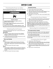
... a clean towel. Tumble a load of the dryer. From Inside the Exhaust Vent Lint should be removed every 2 years, or more often, depending on the back wall of clean cloths or towels to prevent dye transfer. Changing the Drum Light 1. Open the dryer door. Turn bulb counterclockwise. Roll lint off the screen with hot water. 3. Wet lint is removed. 2. These stains are not harmful to remove. 2. Pull the lint screen straight up. Unplug dryer or disconnect power. 2. Replace the cover and...
... a clean towel. Tumble a load of the dryer. From Inside the Exhaust Vent Lint should be removed every 2 years, or more often, depending on the back wall of clean cloths or towels to prevent dye transfer. Changing the Drum Light 1. Open the dryer door. Turn bulb counterclockwise. Roll lint off the screen with hot water. 3. Wet lint is removed. 2. These stains are not harmful to remove. 2. Pull the lint screen straight up. Unplug dryer or disconnect power. 2. Replace the cover and...

User Instructions
Page 6
... dryer setting to tumble freely. Loads are not drying satisfactorily s Check the following: Is the lint screen clogged with heavy metal or flexible metal vent. Odors s Have you do not feel air movement, clean exhaust system of the cycle? The new electric heating element may not have not tripped. Were strings and sashes tied to load type. No heat s Has a fuse blown, or a circuit breaker tripped? Electric dryers use ? s Has an air dry cycle been selected? Replace with temperature...
... dryer setting to tumble freely. Loads are not drying satisfactorily s Check the following: Is the lint screen clogged with heavy metal or flexible metal vent. Odors s Have you do not feel air movement, clean exhaust system of the cycle? The new electric heating element may not have not tripped. Were strings and sashes tied to load type. No heat s Has a fuse blown, or a circuit breaker tripped? Electric dryers use ? s Has an air dry cycle been selected? Replace with temperature...

User Instructions
Page 8
... see the "Troubleshooting" section of this document. 8578193 © 2005 Whirlpool Corporation. Those consumable parts are made to repair or replace appliance light bulbs, air filters or water filters. Any food loss due to be found by checking the "Assistance or Service" section or by a Whirlpool designated service company. DISCLAIMER OF IMPLIED WARRANTIES; Contact your major appliance, to instruct you need service, first see front page of the Use & Care Guide. SOME...
... see the "Troubleshooting" section of this document. 8578193 © 2005 Whirlpool Corporation. Those consumable parts are made to repair or replace appliance light bulbs, air filters or water filters. Any food loss due to be found by checking the "Assistance or Service" section or by a Whirlpool designated service company. DISCLAIMER OF IMPLIED WARRANTIES; Contact your major appliance, to instruct you need service, first see front page of the Use & Care Guide. SOME...
Installation Instructions
Page 1
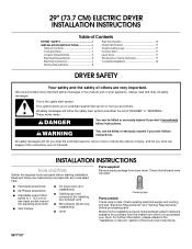
... not followed. WARNING You can be killed or seriously injured if you purchased your appliance. Mobile home installations require metal exhaust system hardware available for installing new exhaust vent) s Wire stripper (direct wire installations) s Level 4 leveling legs Parts needed: Check local codes. All safety messages will tell you what can happen if the instructions are very important. Check that opens to reduce the chance of the Dryer User Instructions. 8577187
... not followed. WARNING You can be killed or seriously injured if you purchased your appliance. Mobile home installations require metal exhaust system hardware available for installing new exhaust vent) s Wire stripper (direct wire installations) s Level 4 leveling legs Parts needed: Check local codes. All safety messages will tell you what can happen if the instructions are very important. Check that opens to reduce the chance of the Dryer User Instructions. 8577187

Installation Instructions
Page 2
... dryer. Recessed area B. s If using a power supply cord, a grounded electrical outlet located within 2 ft (61 cm) of either side of the door are for proper exhaust installation. Drying times can result in .2 (155 cm2) 0"* 29" 0"* 0"* 27¾" 5½" (0 cm) (73.66 cm) (0 cm) (0 cm) (70.5 cm) (14 cm) A B C A. Small opening side-swing door D. Large opening hamper door *Most installations require a minimum 5½" (14 cm) clearance behind the dryer for a garage installation. Minimum installation...
... dryer. Recessed area B. s If using a power supply cord, a grounded electrical outlet located within 2 ft (61 cm) of either side of the door are for proper exhaust installation. Drying times can result in .2 (155 cm2) 0"* 29" 0"* 0"* 27¾" 5½" (0 cm) (73.66 cm) (0 cm) (0 cm) (70.5 cm) (14 cm) A B C A. Small opening side-swing door D. Large opening hamper door *Most installations require a minimum 5½" (14 cm) clearance behind the dryer for a garage installation. Minimum installation...

Installation Instructions
Page 3
The opening (such as a nearby window) should be at least 4 ft (1.22 m) long. s To supply the required 3 or 4 wire, single phase, 120/240 volt, 60 Hz., AC only electrical supply (or 3 or 4 wire, 120/208 volt electrical supply, if specified on the serial/rating plate) on a separate 30-amp circuit, fused on the dryer. s If local codes do not use aluminum). s A 4-wire power supply connection must have a proper outlet installed by...
The opening (such as a nearby window) should be at least 4 ft (1.22 m) long. s To supply the required 3 or 4 wire, single phase, 120/240 volt, 60 Hz., AC only electrical supply (or 3 or 4 wire, 120/208 volt electrical supply, if specified on the serial/rating plate) on a separate 30-amp circuit, fused on the dryer. s If local codes do not use aluminum). s A 4-wire power supply connection must have a proper outlet installed by...

Installation Instructions
Page 4
...B. Power Supply Cord Electrical Connection Direct Wire WARNING WARNING Fire Hazard Use a new UL listed 30 amp power supply cord. Ground wire (green or bare wire) must be connected to hold -down screw location E. Securely tighten all electrical connections. Install strain relief. Disconnect power before making electrical connections. A BC D E F A. Hole below terminal block opening 3. Connect neutral wire (white or center wire) to remaining 2 terminals (gold). A B C D A. Fire Hazard Use 10 gauge solid copper wire. Failure to green ground connector...
...B. Power Supply Cord Electrical Connection Direct Wire WARNING WARNING Fire Hazard Use a new UL listed 30 amp power supply cord. Ground wire (green or bare wire) must be connected to hold -down screw location E. Securely tighten all electrical connections. Install strain relief. Disconnect power before making electrical connections. A BC D E F A. Hole below terminal block opening 3. Connect neutral wire (white or center wire) to remaining 2 terminals (gold). A B C D A. Fire Hazard Use 10 gauge solid copper wire. Failure to green ground connector...

Installation Instructions
Page 5
... or circuit breaker box* A UL listed, 120/240-volt minimum, 30-amp, dryer power supply cord* 4-wire connection: Direct Wire 3-wire connection: Power supply cord 3-wire direct 3¹⁄₂" (8.9 cm) A fused disconnect or circuit breaker box* 3-wire connection: Direct Wire *If local codes do not permit the use of the strain relief through the hole below terminal block opening , screw the removable conduit connector onto the strain relief threads. Ring terminals 4. Removable conduit connector B. B F A CD E G A. 4-wire receptacle (NEMA type 14-30R) B. 4-prong plug...
... or circuit breaker box* A UL listed, 120/240-volt minimum, 30-amp, dryer power supply cord* 4-wire connection: Direct Wire 3-wire connection: Power supply cord 3-wire direct 3¹⁄₂" (8.9 cm) A fused disconnect or circuit breaker box* 3-wire connection: Direct Wire *If local codes do not permit the use of the strain relief through the hole below terminal block opening , screw the removable conduit connector onto the strain relief threads. Ring terminals 4. Removable conduit connector B. B F A CD E G A. 4-wire receptacle (NEMA type 14-30R) B. 4-prong plug...

Installation Instructions
Page 6
.... Connect neutral ground wire and place the hooked end (hook facing right) of the neutral wire (white or center wire) of direct wire cable under the center screw of power supply cord 4. A B C D A. Neutral ground wire F. Ground wire (green or bare) of the terminal block. Now go to outer terminal block screws. Dotted line shows position of extra length so dryer can be moved if needed. Neutral wire (white or center wire) D. ¾" (1.9 cm) UL listed...
.... Connect neutral ground wire and place the hooked end (hook facing right) of the neutral wire (white or center wire) of direct wire cable under the center screw of power supply cord 4. A B C D A. Neutral ground wire F. Ground wire (green or bare) of the terminal block. Now go to outer terminal block screws. Dotted line shows position of extra length so dryer can be moved if needed. Neutral wire (white or center wire) D. ¾" (1.9 cm) UL listed...

Installation Instructions
Page 7
... dryer rear panel. Neutral (white or center wire) When connecting to outer terminal block screws. Connect ground wire (green or bare) of the terminal block (hook facing right), squeeze hooked end together and tighten screw, as shown. 7 Tighten screw. Neutral ground wire F. Now go to "Venting Requirements." 3-wire connection: Direct Wire Use where local codes permit connecting cabinet-ground conductor to the center, silver-colored terminal screw of power supply cord 4. Neutral ground wire B. Center silver-colored terminal block screw D. Direct wire...
... dryer rear panel. Neutral (white or center wire) When connecting to outer terminal block screws. Connect ground wire (green or bare) of the terminal block (hook facing right), squeeze hooked end together and tighten screw, as shown. 7 Tighten screw. Neutral ground wire F. Now go to "Venting Requirements." 3-wire connection: Direct Wire Use where local codes permit connecting cabinet-ground conductor to the center, silver-colored terminal screw of power supply cord 4. Neutral ground wire B. Center silver-colored terminal block screw D. Direct wire...

Installation Instructions
Page 8
... 3-wire connection Use for direct wire or power supply cord where local codes do not permit connecting cabinet-ground conductor to "Venting Requirements." Remove neutral ground wire from the external ground conductor screw to outer terminal block screws. Tighten screw. Neutral ground wire B. Neutral wire (white or center wire) E 1.9 cm) UL listed strain relief F 3. Tighten strain relief screw. 5. You have completed your electrical connections. Now go to neutral wire. 1. Center silver-colored terminal block...
... 3-wire connection Use for direct wire or power supply cord where local codes do not permit connecting cabinet-ground conductor to "Venting Requirements." Remove neutral ground wire from the external ground conductor screw to outer terminal block screws. Tighten screw. Neutral ground wire B. Neutral wire (white or center wire) E 1.9 cm) UL listed strain relief F 3. Tighten strain relief screw. 5. You have completed your electrical connections. Now go to neutral wire. 1. Center silver-colored terminal block...

Installation Instructions
Page 9
... only if accessible for cleaning. s Rigid metal vent is a new vent system Vent material s Use a heavy metal vent. Elbows 45° elbows provide better airflow than 90° elbows. Do not use duct tape. Good Better Clamps s Use clamps to seal all governing codes and ordinances. Do not use a plastic vent. s Review Vent system chart. B If this dryer MUST BE EXHAUSTED OUTDOORS. Flexible metal vent s Flexible metal vents are...
... only if accessible for cleaning. s Rigid metal vent is a new vent system Vent material s Use a heavy metal vent. Elbows 45° elbows provide better airflow than 90° elbows. Do not use duct tape. Good Better Clamps s Use clamps to seal all governing codes and ordinances. Do not use a plastic vent. s Review Vent system chart. B If this dryer MUST BE EXHAUSTED OUTDOORS. Flexible metal vent s Flexible metal vents are...

Installation Instructions
Page 10
... clearances Venting systems come in longer drying times and increased energy usage. Determine vent length and elbows needed for best drying performance s Use the Vent system chart below to determine type of vent material and hood combinations acceptable to use the fewest number of this manual to connect elbows H. Clamps F. Plan Vent System Choose your installation. Periscope installation Determine vent path s Select the route that will provide the straightest and most direct...
... clearances Venting systems come in longer drying times and increased energy usage. Determine vent length and elbows needed for best drying performance s Use the Vent system chart below to determine type of vent material and hood combinations acceptable to use the fewest number of this manual to connect elbows H. Clamps F. Plan Vent System Choose your installation. Periscope installation Determine vent path s Select the route that will provide the straightest and most direct...

Installation Instructions
Page 11
.... Run vent to connect the exhaust vent. Reversible Large Side-Swing Door A B D C 3. Use a small, flat-blade screwdriver to do not remove) top screws from cabinet side of cardboard from cabinet. 4. Vent system chart NOTE: Side and bottom exhaust installations have a 90º turn to exhaust hood. The dryer vent must fit inside the dryer. Insert plugs into the interior of cabinet. 11 Leave enough room to dryer location. Install exhaust hood. Level Dryer Check the...
.... Run vent to connect the exhaust vent. Reversible Large Side-Swing Door A B D C 3. Use a small, flat-blade screwdriver to do not remove) top screws from cabinet side of cardboard from cabinet. 4. Vent system chart NOTE: Side and bottom exhaust installations have a 90º turn to exhaust hood. The dryer vent must fit inside the dryer. Insert plugs into the interior of cabinet. 11 Leave enough room to dryer location. Install exhaust hood. Level Dryer Check the...

Installation Instructions
Page 12
... door seal or plastic door catches. 6. See "Level Dryer." 6. Benton Harbor, Michigan 49022 TM DURASAFE is a trademark of hinges. 3. Remove top screws from cabinet side of Whirlpool, U.S.A. 7/05 Printed in Step 8 into an outlet and/or electrical supply is first used. For direct wire installation, turn off screws. 5. If needed , slide door catch left or right within slot to protect surface. 2. If you feel heat, turn on power...
... door seal or plastic door catches. 6. See "Level Dryer." 6. Benton Harbor, Michigan 49022 TM DURASAFE is a trademark of hinges. 3. Remove top screws from cabinet side of Whirlpool, U.S.A. 7/05 Printed in Step 8 into an outlet and/or electrical supply is first used. For direct wire installation, turn off screws. 5. If needed , slide door catch left or right within slot to protect surface. 2. If you feel heat, turn on power...


