Installation Instructions
Page 1
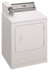
INSTALLATION INSTRUCTIONS COMMERCIAL DRYER Gas (120-Volt, 60-Hz) or Electric (120/240-Volt, 60-Hz) Table of Contents 2 8563800B www.roper.com
INSTALLATION INSTRUCTIONS COMMERCIAL DRYER Gas (120-Volt, 60-Hz) or Electric (120/240-Volt, 60-Hz) Table of Contents 2 8563800B www.roper.com
Installation Instructions
Page 2
...can be obtained from your appliance. TABLE OF CONTENTS DRYER SAFETY 2 INSTALLATION REQUIREMENTS 4 Tools and Parts 4 Location Requirements 5 Electrical Requirements 6 Gas Supply Requirements 7 Venting Requirements 8 INSTALLATION INSTRUCTIONS - GAS DRYER 10 Connect Vent 10 Complete Installation 10 INSTALLATION INSTRUCTIONS ...is the safety alert symbol. GAS DRYER 10 Install Coin Slide and Coin Box 10 Make Gas Connection 10 INSTALLATION INSTRUCTIONS - ELECTRIC DRYER ........ 11 Install Coin Slide and Coin Box 11 Make Electrical Connection 11 Connect Vent 15 Complete ...
...can be obtained from your appliance. TABLE OF CONTENTS DRYER SAFETY 2 INSTALLATION REQUIREMENTS 4 Tools and Parts 4 Location Requirements 5 Electrical Requirements 6 Gas Supply Requirements 7 Venting Requirements 8 INSTALLATION INSTRUCTIONS - GAS DRYER 10 Connect Vent 10 Complete Installation 10 INSTALLATION INSTRUCTIONS ...is the safety alert symbol. GAS DRYER 10 Install Coin Slide and Coin Box 10 Make Gas Connection 10 INSTALLATION INSTRUCTIONS - ELECTRIC DRYER ........ 11 Install Coin Slide and Coin Box 11 Make Electrical Connection 11 Connect Vent 15 Complete ...
Installation Instructions
Page 3
... supplier's instructions. • If you cannot reach your gas supplier from a neighbor's phone. do not use gasoline or other appliance. - Installation and service must be electrically grounded in accordance with local codes, or in the absence of local codes, with the National Fuel Gas Code, ANSI Z223.1/NFPA 54 or the... vicinity of this manual must be followed to minimize the risk of fire or explosion, or to prevent property damage, personal injury, or death. - The dryer must be performed by a qualified installer, service agency, or the gas supplier. 3
... supplier's instructions. • If you cannot reach your gas supplier from a neighbor's phone. do not use gasoline or other appliance. - Installation and service must be electrically grounded in accordance with local codes, or in the absence of local codes, with the National Fuel Gas Code, ANSI Z223.1/NFPA 54 or the... vicinity of this manual must be followed to minimize the risk of fire or explosion, or to prevent property damage, personal injury, or death. - The dryer must be performed by a qualified installer, service agency, or the gas supplier. 3
Installation Instructions
Page 5
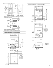
...25-1/2" (648 mm) 35" (889 mm) SIDE VIEW non-coin-operated models: 7-1/8" (181 mm) coin-operated models: 7-7/8" (200 mm) Product Dimensions 27" (686 mm) dryer 27" (686 mm) ELECTRIC 14" (356 mm) BACK VIEW 37" (940 mm) 6-3/4" (152 mm) 13" (330 mm) GAS 4" (102 mm) dia. 4-3/4" (121 mm) EXHAUST 1-1/4" (32...moldings may be required or if external exhaust elbow is the minimum for a closet door. in . (155 sq. Product Dimensions 29" (737 mm) dryer 29" (737 mm) BACK VIEW ELECTRIC 16" (406 mm) 4-3/4" (121 mm) 13" (330 mm) 4" (102 mm) dia. in . (310 sq. Louvered doors with equivalent ...
...25-1/2" (648 mm) 35" (889 mm) SIDE VIEW non-coin-operated models: 7-1/8" (181 mm) coin-operated models: 7-7/8" (200 mm) Product Dimensions 27" (686 mm) dryer 27" (686 mm) ELECTRIC 14" (356 mm) BACK VIEW 37" (940 mm) 6-3/4" (152 mm) 13" (330 mm) GAS 4" (102 mm) dia. 4-3/4" (121 mm) EXHAUST 1-1/4" (32...moldings may be required or if external exhaust elbow is the minimum for a closet door. in . (155 sq. Product Dimensions 29" (737 mm) dryer 29" (737 mm) BACK VIEW ELECTRIC 16" (406 mm) 4-3/4" (121 mm) 13" (330 mm) 4" (102 mm) dia. in . (310 sq. Louvered doors with equivalent ...
Installation Instructions
Page 6
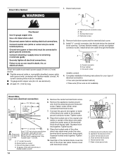
Electric Dryer IMPORTANT: The dryer must be electrically grounded in accordance with local codes and ordinances or, in the absence of electric shock. A time-delay fuse or circuit breaker is required. or 20-amp, fused electrical circuit is recommended. The plug must be plugged ...-Hz, AC-only, 15- A copy of least resistance for electric current. Gas Dryer Electrical Requirements - This dryer is also recommended. The National Electrical Code requires a 4-wire supply connection for homes built after 1996, dryer circuits involved in the absence of the above code standards can be...
Electric Dryer IMPORTANT: The dryer must be electrically grounded in accordance with local codes and ordinances or, in the absence of electric shock. A time-delay fuse or circuit breaker is required. or 20-amp, fused electrical circuit is recommended. The plug must be plugged ...-Hz, AC-only, 15- A copy of least resistance for electric current. Gas Dryer Electrical Requirements - This dryer is also recommended. The National Electrical Code requires a 4-wire supply connection for homes built after 1996, dryer circuits involved in the absence of the above code standards can be...
Installation Instructions
Page 11
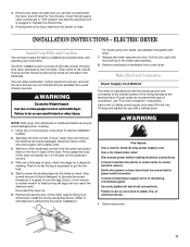
...use adapter kit supplied with lock and key in "ON" position and that the electrical cord is clean. Disconnect power. 11 If the burner does not ignite and you reach the diamond mark. ELECTRIC DRYER Install Coin Slide and Coin Box The console houses the factory-installed accumulator timer with... a clothes dryer. The coin slide mechanism, control panel lock and key, and coin box lock and key...
...use adapter kit supplied with lock and key in "ON" position and that the electrical cord is clean. Disconnect power. 11 If the burner does not ignite and you reach the diamond mark. ELECTRIC DRYER Install Coin Slide and Coin Box The console houses the factory-installed accumulator timer with... a clothes dryer. The coin slide mechanism, control panel lock and key, and coin box lock and key...
Installation Instructions
Page 12
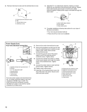
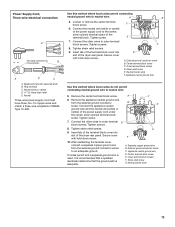
... a four-wire receptacle of the terminal block cover into the hole below the terminal block opening. Fasten under the center screw of electrical connection: • Four-wire (recommended method) • Three-wire (if four-wire is not available) Power Supply Cord, Four-wire... wire C. Hold-down screw and the terminal block cover. Install power supply cord/cable through the strain relief. Connect the ground wire of the dryer rear panel. Tighten screw. 9. Insert tab of NEMA Type 14-30R. A B C G F D E A. Center terminal block screw D. Ground wire 12 External ...
... a four-wire receptacle of the terminal block cover into the hole below the terminal block opening. Fasten under the center screw of electrical connection: • Four-wire (recommended method) • Three-wire (if four-wire is not available) Power Supply Cord, Four-wire... wire C. Hold-down screw and the terminal block cover. Install power supply cord/cable through the strain relief. Connect the ground wire of the dryer rear panel. Tighten screw. 9. Insert tab of NEMA Type 14-30R. A B C G F D E A. Center terminal block screw D. Ground wire 12 External ...
Installation Instructions
Page 13
Power Supply Cord, Three-wire electrical connection: A This blade connected to B this method where local codes permit connecting neutral ground wire to ... wires to an adequate ground. Insert tab of the terminal block cover into D slot of the dryer rear panel. Secure cover with upturned ends B. After reattaching the terminal cover, connect a separate copper...terminal block screw. Tighten screw. 7. Insert tab of the terminal block cover into slot of the dryer rear panel. Appliance neutral ground wire Use this method where local codes do not permit connecting neutral...
Power Supply Cord, Three-wire electrical connection: A This blade connected to B this method where local codes permit connecting neutral ground wire to ... wires to an adequate ground. Insert tab of the terminal block cover into D slot of the dryer rear panel. Secure cover with upturned ends B. After reattaching the terminal cover, connect a separate copper...terminal block screw. Tighten screw. 7. Insert tab of the terminal block cover into slot of the dryer rear panel. Appliance neutral ground wire Use this method where local codes do not permit connecting neutral...
Installation Instructions
Page 14
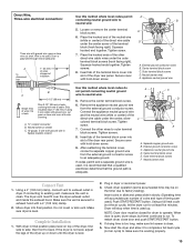
...conduit connector into a hook. I 10-gauge solid copper wire (do not use aluminum). Conduit connector B. Strip 5" (127 mm) of outer covering from end of the dryer rear panel. Leave green or bare ground wire at 5" (127 mm). Strip insulation back 1" (25 mm). Tighten screw. 9. Neutral (center wire) F. Terminal block ...or 3-wire) and be insulated. I At least 5 ft. (1.52 m) long. Complete installation following instructions for your type of electrical connection: • Four-wire (recommended method) • Three-wire (if four-wire is not available) Direct Wire, Four-wire...
...conduit connector into a hook. I 10-gauge solid copper wire (do not use aluminum). Conduit connector B. Strip 5" (127 mm) of outer covering from end of the dryer rear panel. Leave green or bare ground wire at 5" (127 mm). Strip insulation back 1" (25 mm). Tighten screw. 9. Neutral (center wire) F. Terminal block ...or 3-wire) and be insulated. I At least 5 ft. (1.52 m) long. Complete installation following instructions for your type of electrical connection: • Four-wire (recommended method) • Three-wire (if four-wire is not available) Direct Wire, Four-wire...
Installation Instructions
Page 15
..., connect vent to outer terminal block screws. then front to an adequate ground. NOTE: Dryer door must fit over the dryer exhaust outlet and inside the exhaust hood. Direct Wire, Three-wire electrical connection: Three wire with ground wire: green or bare wire cut green or bare wire ...even with outer covering. Dryer is secured to neutral wire: 5. Place the hooked ends of the dryer rear panel. B 3-1/2" (89 mm) Strip 3-1⁄...
..., connect vent to outer terminal block screws. then front to an adequate ground. NOTE: Dryer door must fit over the dryer exhaust outlet and inside the exhaust hood. Direct Wire, Three-wire electrical connection: Three wire with ground wire: green or bare wire cut green or bare wire ...even with outer covering. Dryer is secured to neutral wire: 5. Place the hooked ends of the dryer rear panel. B 3-1/2" (89 mm) Strip 3-1⁄...
Installation Instructions
Page 16
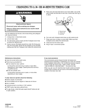
...the V-shaped notch clears the ratchet tooth. Unplug dryer or disconnect power. 2. Gently lift cam straight up below the ratchet tooth. 4. Maintenance instructions: I Electric supply is in the dryer door well. 8563800B © 2008. If dryer does not operate check the following: I Clean ...lug is connected. I START button has been pushed firmly. I Controls are not blown. A B Electrical Shock Hazard Disconnect power before each cycle. C A. I From inside the dryer cabinet: Lint should be removed every 2 years or more often, depending on the serial-rating plate ...
...the V-shaped notch clears the ratchet tooth. Unplug dryer or disconnect power. 2. Gently lift cam straight up below the ratchet tooth. 4. Maintenance instructions: I Electric supply is in the dryer door well. 8563800B © 2008. If dryer does not operate check the following: I Clean ...lug is connected. I START button has been pushed firmly. I Controls are not blown. A B Electrical Shock Hazard Disconnect power before each cycle. C A. I From inside the dryer cabinet: Lint should be removed every 2 years or more often, depending on the serial-rating plate ...


