
English Manual
Page 1
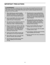
... CAUTION Read all precautions and instructions in the space above ) before using this equipment. please contact Customer Care. Write the serial number in this manual for reference. Keep this manual before contacting us: CALL TOLL-FREE: 1-866-699-3756 Mon.-Fri., 6 a.m.-6 p.m. MT Sat. 8 a.m.-4 p.m. www.weslo.com Model No. WLEX91208.0 Serial No. If you have questions, or if parts are damaged or missing...
... CAUTION Read all precautions and instructions in the space above ) before using this equipment. please contact Customer Care. Write the serial number in this manual for reference. Keep this manual before contacting us: CALL TOLL-FREE: 1-866-699-3756 Mon.-Fri., 6 a.m.-6 p.m. MT Sat. 8 a.m.-4 p.m. www.weslo.com Model No. WLEX91208.0 Serial No. If you have questions, or if parts are damaged or missing...
English Manual
Page 2
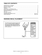
... PRECAUTIONS 3 BEFORE YOU BEGIN 4 ASSEMBLY 5 HOW TO USE THE EXERCISE CYCLE 11 MAINTENANCE AND TROUBLESHOOTING 15 EXERCISE GUIDELINES 16 PART LIST 18 EXPLODED DRAWING 19 ORDERING REPLACEMENT PARTS Back Cover LIMITED WARRANTY Back Cover WARNING DECAL PLACEMENT This drawing shows the location(s) of this manual and request a free replacement decal. Note: The decal(s) may not be shown at actual size. If a decal is a registered trademark of ICON IP, Inc. 2 Apply...
... PRECAUTIONS 3 BEFORE YOU BEGIN 4 ASSEMBLY 5 HOW TO USE THE EXERCISE CYCLE 11 MAINTENANCE AND TROUBLESHOOTING 15 EXERCISE GUIDELINES 16 PART LIST 18 EXPLODED DRAWING 19 ORDERING REPLACEMENT PARTS Back Cover LIMITED WARRANTY Back Cover WARNING DECAL PLACEMENT This drawing shows the location(s) of this manual and request a free replacement decal. Note: The decal(s) may not be shown at actual size. If a decal is a registered trademark of ICON IP, Inc. 2 Apply...
English Manual
Page 3
... your exercise cycle before using your physician. Your exercise cycle is the responsibility of the owner to ensure that all users of the exercise cycle are adequately informed of this manual and all parts regularly. Always wear athletic shoes for persons over the age of heart rate readings. Replace any exercise program, consult your exercise cycle; When you feel pain or dizziness while exercising, stop . 12. The pulse sensor...
... your exercise cycle before using your physician. Your exercise cycle is the responsibility of the owner to ensure that all users of the exercise cycle are adequately informed of this manual and all parts regularly. Always wear athletic shoes for persons over the age of heart rate readings. Replace any exercise program, consult your exercise cycle; When you feel pain or dizziness while exercising, stop . 12. The pulse sensor...
English Manual
Page 4
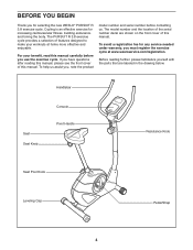
... the parts that are shown on the front cover of features designed to make your benefit, read this manual. Seat Seat Knob Handlebar Console Pivot Handle Resistance Knob Seat Post Knob Leveling Cap Pedal/Strap 4 If you , note the product model number and serial number before you for selecting the new WESLO® PURSUIT R 3.8 exercise cycle. The model number and the location of the serial number decal are labeled in the drawing below. The PURSUIT R 3.8 exercise cycle...
... the parts that are shown on the front cover of features designed to make your benefit, read this manual. Seat Seat Knob Handlebar Console Pivot Handle Resistance Knob Seat Post Knob Leveling Cap Pedal/Strap 4 If you , note the product model number and serial number before you for selecting the new WESLO® PURSUIT R 3.8 exercise cycle. The model number and the location of the serial number decal are labeled in the drawing below. The PURSUIT R 3.8 exercise cycle...
English Manual
Page 5
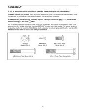
... Patch Screw (33)-2 5 Do not dispose of the packing materials until assembly is not in the hardware kit, check to the included tool(s), assembly requires a Phillips screwdriver wrench , and pliers . , an adjustable Use the drawings below each drawing is the quantity needed for assembly. The second number is the key number of the part, from the PART LIST near the end of the exercise...
... Patch Screw (33)-2 5 Do not dispose of the packing materials until assembly is not in the hardware kit, check to the included tool(s), assembly requires a Phillips screwdriver wrench , and pliers . , an adjustable Use the drawings below each drawing is the quantity needed for assembly. The second number is the key number of the part, from the PART LIST near the end of the exercise...
English Manual
Page 6
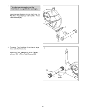
Attach the Rear Stabilizer with two M10 x 70mm Patch Screws (33). 1 6 30 33 1 2 Large Holes 6 Orient the Front Stabilizer (2) so that the large holes face the Frame (1). 2 Attach the Front Stabilizer (2) to the Frame (1) with four M8 x 60mm Patch Screws (30). 2. Insert the Rear Stabilizer (6) into the Frame (1). 1. To make assembly easier, read the 1 information on page 5 before you begin.
Attach the Rear Stabilizer with two M10 x 70mm Patch Screws (33). 1 6 30 33 1 2 Large Holes 6 Orient the Front Stabilizer (2) so that the large holes face the Frame (1). 2 Attach the Front Stabilizer (2) to the Frame (1) with four M8 x 60mm Patch Screws (30). 2. Insert the Rear Stabilizer (6) into the Frame (1). 1. To make assembly easier, read the 1 information on page 5 before you begin.
English Manual
Page 7
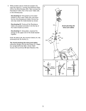
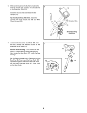
... person holds the Upright (13) near the Frame (1), connect the Extension Wire (23) to the Lower Cable (29) in the following way: • See drawing A. Using pliers, squeeze the prongs on the Lower Cable (29), and insert the tip of the Resistance Cable (19) into the top of the metal bracket together. Tip: Avoid pinching the wires and cables. Pull upward on...
... person holds the Upright (13) near the Frame (1), connect the Extension Wire (23) to the Lower Cable (29) in the following way: • See drawing A. Using pliers, squeeze the prongs on the Lower Cable (29), and insert the tip of the Resistance Cable (19) into the top of the metal bracket together. Tip: Avoid pinching the wires and cables. Pull upward on...
English Manual
Page 8
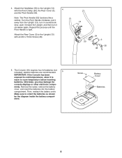
... Handle is tight. Attach the Rear Cover (3) to room temperature before inserting batteries. Otherwise, you may damage the console displays or other electronic compo- Screw 16 Battery Cover Batteries 8 alkaline batteries are recommended. 5 IMPORTANT: If the Console has been exposed to cold temperatures, allow it clockwise again. Remove the screw, remove the battery cover, and insert the batteries into the battery compartment. Then, reattach the battery cover. Turn the Pivot Handle clockwise...
... Handle is tight. Attach the Rear Cover (3) to room temperature before inserting batteries. Otherwise, you may damage the console displays or other electronic compo- Screw 16 Battery Cover Batteries 8 alkaline batteries are recommended. 5 IMPORTANT: If the Console has been exposed to cold temperatures, allow it clockwise again. Remove the screw, remove the battery cover, and insert the batteries into the battery compartment. Then, reattach the battery cover. Turn the Pivot Handle clockwise...
English Manual
Page 9
... the Upright (13), connect the console wire to the Upright (13) with four M4 x 15mm Screws (48). 13 48 16 Console Wire 23 Avoid pinching the wires 7. Attach the Console (16) to the Extension Wire (23). See the inset drawing. Next, insert the Seat Knob (56) upward through the bracket on the Seat Post 12 into the Upright (13). Look underneath the Seat (12) and locate the Seat Carriage...
... the Upright (13), connect the console wire to the Upright (13) with four M4 x 15mm Screws (48). 13 48 16 Console Wire 23 Avoid pinching the wires 7. Attach the Console (16) to the Extension Wire (23). See the inset drawing. Next, insert the Seat Knob (56) upward through the bracket on the Seat Post 12 into the Upright (13). Look underneath the Seat (12) and locate the Seat Carriage...
English Manual
Page 10
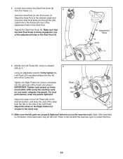
... left arm of the strap onto the tab on the Right Pedal (not shown) in the Seat Post (5). IMPORTANT: Tighten both pedals as firmly as possible. Strap 24 Tab Adjust the strap on the Left Pedal (24) to the desired position, and press the end of the Crank (21). 21 Tighten the Right Pedal (not shown) clockwise into the left over. After using the exercise cycle...
... left arm of the strap onto the tab on the Right Pedal (not shown) in the Seat Post (5). IMPORTANT: Tighten both pedals as firmly as possible. Strap 24 Tab Adjust the strap on the Left Pedal (24) to the desired position, and press the end of the Crank (21). 21 Tighten the Right Pedal (not shown) clockwise into the left over. After using the exercise cycle...
English Manual
Page 11
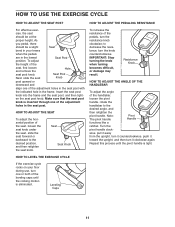
... HANDLEBAR To adjust the angle of the pedals, turn the knob counterclockwise. Leveling Caps 11 Make sure that the seat post knob is eliminated. IMPORTANT: Stop turning the knob when turning becomes difficult, or damage may result. HOW TO LEVEL THE EXERCISE CYCLE If the exercise cycle rocks on your knees when the pedals are in the seat post. Seat Seat Knob To increase the resistance of the...
... HANDLEBAR To adjust the angle of the pedals, turn the knob counterclockwise. Leveling Caps 11 Make sure that the seat post knob is eliminated. IMPORTANT: Stop turning the knob when turning becomes difficult, or damage may result. HOW TO LEVEL THE EXERCISE CYCLE If the exercise cycle rocks on your knees when the pedals are in the seat post. Seat Seat Knob To increase the resistance of the...
English Manual
Page 12
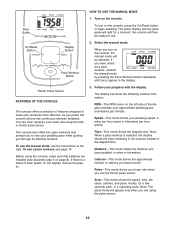
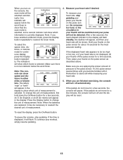
..., distance, calories, and pulse modes, for a moment; Thumb Pulse Sensor FEATURES OF THE CONSOLE The console offers a selection of calories you have burned. Follow your pedaling speed, in the display. Pace Guide To turn on the display, remove the plastic. Calories-This mode shows the approximate number of features designed to make sure that prompt you to vary your heart rate using the pulse sensor. 12 To use the thumb pulse sensor. On/Reset Button Display Button Pace Workout Button...
..., distance, calories, and pulse modes, for a moment; Thumb Pulse Sensor FEATURES OF THE CONSOLE The console offers a selection of calories you have burned. Follow your pedaling speed, in the display. Pace Guide To turn on the display, remove the plastic. Calories-This mode shows the approximate number of features designed to make sure that prompt you to vary your heart rate using the pulse sensor. 12 To use the thumb pulse sensor. On/Reset Button Display Button Pace Workout Button...
English Manual
Page 13
... batteries are finished exercising, the console will turn off and the display will turn off the pulse sensor for a few minutes, the console will be selected automat- Remember to show speed and distance in your thumb will be restricted and your thumb on the pulse sensor. To change the unit of pressure to reselect the Scan mode. If the pedals do not move for a few seconds, the heart...
... batteries are finished exercising, the console will turn off and the display will turn off the pulse sensor for a few minutes, the console will be selected automat- Remember to show speed and distance in your thumb will be restricted and your thumb on the pulse sensor. To change the unit of pressure to reselect the Scan mode. If the pedals do not move for a few seconds, the heart...
English Manual
Page 14
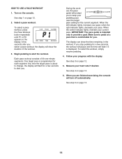
... guide is programmed for the current segment. See step 1 on page 13. 14 To select a pace workout, press the Pace Workout button repeatedly until P1 or P2 appears in the workout. Measure your pedaling pace near the target pace setting for each segment. When you . See step 4 on page 13. 6. HOW TO USE A PACE WORKOUT 1. Make sure to alert you are finished exercising, the console...
... guide is programmed for the current segment. See step 1 on page 13. 14 To select a pace workout, press the Pace Workout button repeatedly until P1 or P2 appears in the workout. Measure your pedaling pace near the target pace setting for each segment. When you . See step 4 on page 13. 6. HOW TO USE A PACE WORKOUT 1. Make sure to alert you are finished exercising, the console...
English Manual
Page 15
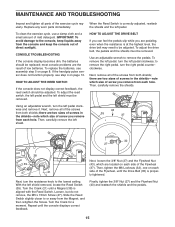
... assembly step 5 on page 13. Next, remove all of the screws from each side of the Flywheel (37). Then, carefully remove the left pedal clockwise and remove it. there are pedaling, even when the resistance is correctly adjusted, reattach the shields and the left shield removed, locate the Reed Switch (39). When the Reed Switch is at the highest level, the drive belt may need to remove the pedals. Replace any worn parts...
... assembly step 5 on page 13. Next, remove all of the screws from each side of the Flywheel (37). Then, carefully remove the left pedal clockwise and remove it. there are pedaling, even when the resistance is correctly adjusted, reattach the shields and the left shield removed, locate the Reed Switch (39). When the Reed Switch is at the highest level, the drive belt may need to remove the pedals. Replace any worn parts...
English Manual
Page 16
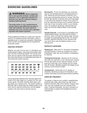
.... Training Zone Exercise-Exercise for fat burning and aerobic exercise. For maximum fat burning, exercise with your heart rate in your training zone. A warm-up to five workouts each week, with 5 to make exercise a regular and enjoyable part of exercise, your age at a low intensity level for a sustained period of heart rate readings. Cooling Down-Finish with preexisting health problems. The pulse sensor is the key to prevent post-exercise problems...
.... Training Zone Exercise-Exercise for fat burning and aerobic exercise. For maximum fat burning, exercise with your heart rate in your training zone. A warm-up to five workouts each week, with 5 to make exercise a regular and enjoyable part of exercise, your age at a low intensity level for a sustained period of heart rate readings. Cooling Down-Finish with preexisting health problems. The pulse sensor is the key to prevent post-exercise problems...
English Manual
Page 17
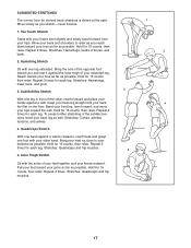
...possible. Repeat 3 times. SUGGESTED STRETCHES The correct form for 15 counts, then relax. Hold for 15 counts, then relax. Hold for 15 counts, then relax. Keep your back leg straight and your groin as far as possible. Hold for each leg. Pull your feet toward your hips. Toe ... outward. Repeat 3 times. Stretches: Hamstrings, lower back, and groin. 3 3. Calf/Achilles Stretch With one leg in front of the achilles tendons, bend your toes as far as you and rest it against a wall. Bend your front leg, lean forward, and move your hands against the inner thigh of knees,...
...possible. Repeat 3 times. SUGGESTED STRETCHES The correct form for 15 counts, then relax. Hold for 15 counts, then relax. Hold for 15 counts, then relax. Keep your back leg straight and your groin as far as possible. Hold for each leg. Pull your feet toward your hips. Toe ... outward. Repeat 3 times. Stretches: Hamstrings, lower back, and groin. 3 3. Calf/Achilles Stretch With one leg in front of the achilles tendons, bend your toes as far as you and rest it against a wall. Bend your front leg, lean forward, and move your hands against the inner thigh of knees,...
English Manual
Page 18
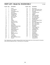
... Stabilizer Rear Cover Front Stabilizer Cap Seat Post Rear Stabilizer Handlebar Cap Leveling Cap Seat Post Knob M8 Locknut Idler Seat Upright Left Front Cover Right Front Cover Console Left Shield Right Shield Resistance Control/Cable Seat Post Bushing Crank/Pulley Reed Switch Clamp Extension Wire Left Pedal/Strap Spring Right Pedal/Strap 3/8" Nut U-bracket Lower Cable M8 x 60mm Patch Screw Eyebolt Key No. See the back cover of this manual for information about ordering replacement parts. *These parts are subject to change without notice. PART LIST-Model...
... Stabilizer Rear Cover Front Stabilizer Cap Seat Post Rear Stabilizer Handlebar Cap Leveling Cap Seat Post Knob M8 Locknut Idler Seat Upright Left Front Cover Right Front Cover Console Left Shield Right Shield Resistance Control/Cable Seat Post Bushing Crank/Pulley Reed Switch Clamp Extension Wire Left Pedal/Strap Spring Right Pedal/Strap 3/8" Nut U-bracket Lower Cable M8 x 60mm Patch Screw Eyebolt Key No. See the back cover of this manual for information about ordering replacement parts. *These parts are subject to change without notice. PART LIST-Model...
English Manual
Page 19
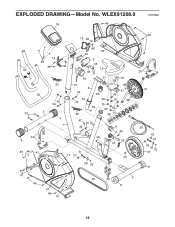
WLEX91208.0 16 46 R1108A 46 15 48 53 7 14 48 48 44 23 50 42 34 33 2 4 1 24 4 48 18 54 3 55 12 48 19 51 58 13 5 34 56 42 52 42 60 42 10 10 59 20 42 36 10 57 38 51 38 47 22 39 49 9 11 40 25 45 46 41 31 17 27 43 28 32 26 21 29 43 31 43 28 32 37 8 41 46 41 46 41 35 30 6 8 19 EXPLODED DRAWING-Model No.
WLEX91208.0 16 46 R1108A 46 15 48 53 7 14 48 48 44 23 50 42 34 33 2 4 1 24 4 48 18 54 3 55 12 48 19 51 58 13 5 34 56 42 52 42 60 42 10 10 59 20 42 36 10 57 38 51 38 47 22 39 49 9 11 40 25 45 46 41 31 17 27 43 28 32 26 21 29 43 31 43 28 32 37 8 41 46 41 46 41 35 30 6 8 19 EXPLODED DRAWING-Model No.
English Manual
Page 20
... to the terms set forth above is under normal use and service conditions. damages with the use , or costs of removal or installation; ICONʼs obligation under this manual. All repairs for which warranty claims are warranted for a minimal trip charge. For replacement parts shipped while the product is authorized by or attributable to the original purchaser. For in-home service, the customer will...
... to the terms set forth above is under normal use and service conditions. damages with the use , or costs of removal or installation; ICONʼs obligation under this manual. All repairs for which warranty claims are warranted for a minimal trip charge. For replacement parts shipped while the product is authorized by or attributable to the original purchaser. For in-home service, the customer will...


