

User Manual
Page 1
... have questions, or if parts are committed to providing complete customer satisfaction. MT ON THE WEB: www.wesloservice.com CAUTION Read all precautions and instructions in the space above ) before using this manual for reference. Write the serial number in this manual before contacting us: CALL TOLL-FREE: 1-866-699-3756 Mon.-Fri., 6 a.m.-6 p.m. USER'S MANUAL www.weslo.com Model No. As a manufacturer, we...
... have questions, or if parts are committed to providing complete customer satisfaction. MT ON THE WEB: www.wesloservice.com CAUTION Read all precautions and instructions in the space above ) before using this manual for reference. Write the serial number in this manual before contacting us: CALL TOLL-FREE: 1-866-699-3756 Mon.-Fri., 6 a.m.-6 p.m. USER'S MANUAL www.weslo.com Model No. As a manufacturer, we...

User Manual
Page 2
... actual size. WESLO is missing or illegible, see the front cover of the warning decal(s). TABLE OF CONTENTS WARNING DECAL PLACEMENT 2 IMPORTANT PRECAUTIONS 3 BEFORE YOU BEGIN 4 ASSEMBLY 5 HOW TO USE THE EXERCISE CYCLE 10 MAINTENANCE AND TROUBLESHOOTING 12 EXERCISE GUIDELINES 13 PART LIST 14 EXPLODED DRAWING 15 ORDERING REPLACEMENT PARTS Back Cover LIMITED WARRANTY Back Cover WARNING DECAL PLACEMENT This drawing shows the location(s) of this manual and request a free replacement...
... actual size. WESLO is missing or illegible, see the front cover of the warning decal(s). TABLE OF CONTENTS WARNING DECAL PLACEMENT 2 IMPORTANT PRECAUTIONS 3 BEFORE YOU BEGIN 4 ASSEMBLY 5 HOW TO USE THE EXERCISE CYCLE 10 MAINTENANCE AND TROUBLESHOOTING 12 EXERCISE GUIDELINES 13 PART LIST 14 EXPLODED DRAWING 15 ORDERING REPLACEMENT PARTS Back Cover LIMITED WARRANTY Back Cover WARNING DECAL PLACEMENT This drawing shows the location(s) of this manual and request a free replacement...

User Manual
Page 3
... all warnings on a level surface, with pre-existing health problems. 2. The pulse sensor is intended for foot protection while exercising. 4. Various factors, including the user's movement, may affect the accuracy of this manual. 3 Always wear athletic shoes for home use of heart rate readings. Make sure that there is the responsibility of the owner to ensure that could become caught on your...
... all warnings on a level surface, with pre-existing health problems. 2. The pulse sensor is intended for foot protection while exercising. 4. Various factors, including the user's movement, may affect the accuracy of this manual. 3 Always wear athletic shoes for home use of heart rate readings. Make sure that there is the responsibility of the owner to ensure that could become caught on your...

User Manual
Page 4
... cover of this manual carefully before contacting us assist you, note the product model number and serial number before you enjoy this healthful exercise in the convenience and privacy of your benefit, read this manual. The PURSUIT 330 exercise cycle offers a selection of features designed to let you use the exercise cycle. Seat Water Bottle Holder* Pulse Sensor Seat Knob 4 Handlebar Console Resistance Knob Pedal/Strap *Water bottle is an effective exercise for increasing cardiovascular fitness...
... cover of this manual carefully before contacting us assist you, note the product model number and serial number before you enjoy this healthful exercise in the convenience and privacy of your benefit, read this manual. The PURSUIT 330 exercise cycle offers a selection of features designed to let you use the exercise cycle. Seat Water Bottle Holder* Pulse Sensor Seat Knob 4 Handlebar Console Resistance Knob Pedal/Strap *Water bottle is an effective exercise for increasing cardiovascular fitness...

User Manual
Page 5
... Screw (49)-4 M4 x 16mm Bright Screw (56)-1 M8 x 15mm Button Screw (34)-3 M8 x 58mm Button Bolt (6)-1 M10 x 65mm Carriage Bolt (30)-4 5 Note: Some small parts may have been preassembled. ASSEMBLY To hire an authorized service technician to assemble the exercise cycle, call 1-800-445-2480. The number following the parentheses is the key number of the part, from the PART LIST near the end of this manual. Place all parts...
... Screw (49)-4 M4 x 16mm Bright Screw (56)-1 M8 x 15mm Button Screw (34)-3 M8 x 58mm Button Bolt (6)-1 M10 x 65mm Carriage Bolt (30)-4 5 Note: Some small parts may have been preassembled. ASSEMBLY To hire an authorized service technician to assemble the exercise cycle, call 1-800-445-2480. The number following the parentheses is the key number of the part, from the PART LIST near the end of this manual. Place all parts...

User Manual
Page 6
... the information on page 5 before inserting batteries. partment. Make sure to room temperature before you may damage the console displays or other electronic compo- nents. Insert the batteries into the battery com- Otherwise, you begin assembling the exercise cycle. Batteries 16 33 2 30 6 While another person lifts the front of the Frame (1), attach a Stabilizer (2) with two M10 x 65mm Carriage Bolts (30...
... the information on page 5 before inserting batteries. partment. Make sure to room temperature before you may damage the console displays or other electronic compo- nents. Insert the batteries into the battery com- Otherwise, you begin assembling the exercise cycle. Batteries 16 33 2 30 6 While another person lifts the front of the Frame (1), attach a Stabilizer (2) with two M10 x 65mm Carriage Bolts (30...

User Manual
Page 7
...). 34 42 34 16 56 Ground Wire 15 Avoid pinching the wires Avoid pinching the wires 15 Console Wire 54 34 42 13 7 Attach the Handlebar (15) to the Extension Wire (54). While another person holds the Console (16) 4 near the Upright (13), connect the console wire 5 to the Upright (13) with an M4 x 16mm Bright Screw (56). Console Wire Hole 49 49 5. While another person...
...). 34 42 34 16 56 Ground Wire 15 Avoid pinching the wires Avoid pinching the wires 15 Console Wire 54 34 42 13 7 Attach the Handlebar (15) to the Extension Wire (54). While another person holds the Console (16) 4 near the Upright (13), connect the console wire 5 to the Upright (13) with an M4 x 16mm Bright Screw (56). Console Wire Hole 49 49 5. While another person...

User Manual
Page 8
... x 58mm Button Bolt (6), an M8 Split Washer (42), and an M8 Locknut (10). Tip: Avoid pinching the cables and wires. Firmly pull the Resistance Cable (19) upward and press it into the Frame (1). Next, connect the Resistance Cable (19) to the Wire Harness (53). Insert the excess cable and wire downward into the top of the Resistance Cable (19) into the Frame. Attach the Upright (13) with...
... x 58mm Button Bolt (6), an M8 Split Washer (42), and an M8 Locknut (10). Tip: Avoid pinching the cables and wires. Firmly pull the Resistance Cable (19) upward and press it into the Frame (1). Next, connect the Resistance Cable (19) to the Wire Harness (53). Insert the excess cable and wire downward into the top of the Resistance Cable (19) into the Frame. Attach the Upright (13) with...

User Manual
Page 9
... Left Pedal. Note: After assembly is inserted through the Frame (1) and the Seat Post (15), and then tighten the Seat Knob. Place a mat beneath the exercise cycle to the desired position, and press the end of the Crank (21). IMPORTANT: Tighten both Pedals as firmly as possible. Attach the Seat Bushing with the hole in the Seat Post with two M4 x 5mm Screws (14). Using an adjustable...
... Left Pedal. Note: After assembly is inserted through the Frame (1) and the Seat Post (15), and then tighten the Seat Knob. Place a mat beneath the exercise cycle to the desired position, and press the end of the Crank (21). IMPORTANT: Tighten both Pedals as firmly as possible. Attach the Seat Bushing with the hole in the Seat Post with two M4 x 5mm Screws (14). Using an adjustable...

User Manual
Page 10
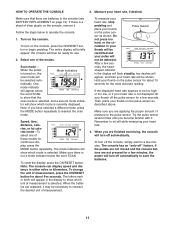
... miles or kilometers. • Calories-This mode displays the approximate number of the adjustment holes in your workouts. To adjust Hole the height of the pedals, turn the knob counterclockwise. As you stop turning the knob when turning it becomes difficult. HOW TO USE THE EXERCISE CYCLE HOW TO ADJUST THE SEAT POST FEATURES OF THE CONSOLE For effective exer- Note: If you pedal, there should be displayed only while the pulse sensor...
... miles or kilometers. • Calories-This mode displays the approximate number of the adjustment holes in your workouts. To adjust Hole the height of the pedals, turn the knob counterclockwise. As you stop turning the knob when turning it becomes difficult. HOW TO USE THE EXERCISE CYCLE HOW TO ADJUST THE SEAT POST FEATURES OF THE CONSOLE For effective exer- Note: If you pedal, there should be displayed only while the pulse sensor...
User Manual
Page 11
... console. Remember to operate the console. 1. If the pedals are not moved and the console buttons are finished exercising, the console will turn off " feature. If there is turned on the console, remove it. Scan mode- tor will briefly appear; To measure your heart rate, stop pedaling and Pulse Sensor place your heart rate, if desired. onds, the heart- If the displayed heart rate appears to save the batteries. 11 Then, place your heart rate. 4. When you are replaced...
... console. Remember to operate the console. 1. If the pedals are not moved and the console buttons are finished exercising, the console will turn off " feature. If there is turned on the console, remove it. Scan mode- tor will briefly appear; To measure your heart rate, stop pedaling and Pulse Sensor place your heart rate, if desired. onds, the heart- If the displayed heart rate appears to save the batteries. 11 Then, place your heart rate. 4. When you are replaced...

User Manual
Page 12
... batteries into the console. In order to the console, keep the console out of the exercise cycle regularly. Turn the Crank for a moment. Turn the Crank (21) until the console displays correct feedback. Retighten the Screw. MAINTENANCE AND TROUBLESHOOTING Inspect and tighten all parts of direct sunlight. Reattach the console to the handlebar, being careful not to the lowest setting With the left shield removed, locate the Reed Switch (43). Next, turn the Left Pedal...
... batteries into the console. In order to the console, keep the console out of the exercise cycle regularly. Turn the Crank for a moment. Turn the Crank (21) until the console displays correct feedback. Retighten the Screw. MAINTENANCE AND TROUBLESHOOTING Inspect and tighten all parts of direct sunlight. Reattach the console to the handlebar, being careful not to the lowest setting With the left shield removed, locate the Reed Switch (43). Next, turn the Left Pedal...

User Manual
Page 13
... device. You can use stored fat calories for successful results. For aerobic exercise, adjust the intensity of heart rate readings. Various factors may affect the accuracy of your exercise until your training zone for maximum fat burning, and the highest number is the key to the nearest ten years). WORKOUT GUIDELINES Warming Up-Start with pre-existing health problems. The pulse sensor is especially important...
... device. You can use stored fat calories for successful results. For aerobic exercise, adjust the intensity of heart rate readings. Various factors may affect the accuracy of your exercise until your training zone for maximum fat burning, and the highest number is the key to the nearest ten years). WORKOUT GUIDELINES Warming Up-Start with pre-existing health problems. The pulse sensor is especially important...

User Manual
Page 14
... 1 Upright 14 2 M4 x 5mm Screw 15 1 Handlebar 16 1 Console 17 1 Left Shield 18 1 Right Shield 19 1 Resistance Control/Cable 20 1 Seat Post Bushing 21 1 Crank/Pulley 22 1 Reed Switch Clamp 23 1 M10 Washer 24 1 Left Pedal/Strap 25 2 6200Z Bearing 26 1 Right Pedal/Strap 27 1 Resistance Knob 28 2 U-bracket 29 1 Crank Nut 30 4 M10 x 65mm Carriage Bolt 31 2 Eyebolt 32 4 M6 Nut 33 4 M10 Locknut 34 3 M8 x 15mm Button Screw 35 1 Drive Belt...
... 1 Upright 14 2 M4 x 5mm Screw 15 1 Handlebar 16 1 Console 17 1 Left Shield 18 1 Right Shield 19 1 Resistance Control/Cable 20 1 Seat Post Bushing 21 1 Crank/Pulley 22 1 Reed Switch Clamp 23 1 M10 Washer 24 1 Left Pedal/Strap 25 2 6200Z Bearing 26 1 Right Pedal/Strap 27 1 Resistance Knob 28 2 U-bracket 29 1 Crank Nut 30 4 M10 x 65mm Carriage Bolt 31 2 Eyebolt 32 4 M6 Nut 33 4 M10 Locknut 34 3 M8 x 15mm Button Screw 35 1 Drive Belt...

User Manual
Page 15
WLEX91108.0 R1108A 7 7 16 56 3 18 15 34 12 30 4 3 41 42 34 49 42 42 34 13 27 54 45 53 10 55 50 4 1 42 19 10 5 49 42 6 8 20 49 14 43 22 2 33 33 36 51 33 32 26 42 24 10 42 10 24 14 44 29 35 21 26 38 39 37 25 23 31 9 25 40 10 28 32 11 46 31 28 32 52 47 10 33 48 4 17 41 2 30 4 15 EXPLODED DRAWING-Model No.
WLEX91108.0 R1108A 7 7 16 56 3 18 15 34 12 30 4 3 41 42 34 49 42 42 34 13 27 54 45 53 10 55 50 4 1 42 19 10 5 49 42 6 8 20 49 14 43 22 2 33 33 36 51 33 32 26 42 24 10 42 10 24 14 44 29 35 21 26 38 39 37 25 23 31 9 25 40 10 28 32 11 46 31 28 32 52 47 10 33 48 4 17 41 2 30 4 15 EXPLODED DRAWING-Model No.

User Manual
Page 16
... ICON IP, Inc. ICON is authorized by ICON. products used as store display models. No other warranties, and any implied warranties of this manual) LIMITED WARRANTY ICON Health & Fitness, Inc. (ICON) warrants this manual) • the key number and description of the replacement part(s) (see the front cover of this product to any and all other warranty beyond that vary from the date of its authorized service centers. To help us assist you specific...
... ICON IP, Inc. ICON is authorized by ICON. products used as store display models. No other warranties, and any implied warranties of this manual) LIMITED WARRANTY ICON Health & Fitness, Inc. (ICON) warrants this manual) • the key number and description of the replacement part(s) (see the front cover of this product to any and all other warranty beyond that vary from the date of its authorized service centers. To help us assist you specific...


