

English Manual
Page 1
.... CAUTION Read all precautions and instructions in the space above for future reference. Serial Number Decal (under frame) ACTIVATE YOUR WARRANTY To register your product and activate your warranty today, go to www.wesloservice.com/ registration. www.weslo.com Model No. Keep this equipment. WLEL81914.0 Serial No. Write the serial number in this manual before using this manual for reference. USER'S MANUAL Or call 1-866-699...
.... CAUTION Read all precautions and instructions in the space above for future reference. Serial Number Decal (under frame) ACTIVATE YOUR WARRANTY To register your product and activate your warranty today, go to www.wesloservice.com/ registration. www.weslo.com Model No. Keep this equipment. WLEL81914.0 Serial No. Write the serial number in this manual before using this manual for reference. USER'S MANUAL Or call 1-866-699...

English Manual
Page 2
... PLACEMENT 2 IMPORTANT PRECAUTIONS 3 BEFORE YOU BEGIN 5 PART IDENTIFICATION CHART 6 ASSEMBLY 7 HOW TO USE THE ELLIPTICAL 14 FCC INFORMATION 18 MAINTENANCE AND TROUBLESHOOTING 19 EXERCISE GUIDELINES 21 PART LIST 22 EXPLODED DRAWING 23 ORDERING REPLACEMENT PARTS Back Cover LIMITED WARRANTY Back Cover WARNING DECAL PLACEMENT This drawing shows the location(s) of ICON Health & Fitness, Inc. 2 WESLO is missing or illegible, see the front cover of this manual and request a free replacement decal. Apply the decal in the...
... PLACEMENT 2 IMPORTANT PRECAUTIONS 3 BEFORE YOU BEGIN 5 PART IDENTIFICATION CHART 6 ASSEMBLY 7 HOW TO USE THE ELLIPTICAL 14 FCC INFORMATION 18 MAINTENANCE AND TROUBLESHOOTING 19 EXERCISE GUIDELINES 21 PART LIST 22 EXPLODED DRAWING 23 ORDERING REPLACEMENT PARTS Back Cover LIMITED WARRANTY Back Cover WARNING DECAL PLACEMENT This drawing shows the location(s) of ICON Health & Fitness, Inc. 2 WESLO is missing or illegible, see the front cover of this manual and request a free replacement decal. Apply the decal in the...

English Manual
Page 3
... back straight while using the elliptical. 12. Replace any exercise program, consult your back. 14. Before beginning any worn parts immediately. 13. Keep your pedaling speed in a controlled way. 6. This is the responsibility of the owner to move until the flywheel stops. IMPORTANT PRECAUTIONS WARNING: To reduce the risk of serious injury, read all important precautions and instructions in this manual. 4. ICON assumes no responsibility...
... back straight while using the elliptical. 12. Replace any exercise program, consult your back. 14. Before beginning any worn parts immediately. 13. Keep your pedaling speed in a controlled way. 6. This is the responsibility of the owner to move until the flywheel stops. IMPORTANT PRECAUTIONS WARNING: To reduce the risk of serious injury, read all important precautions and instructions in this manual. 4. ICON assumes no responsibility...

English Manual
Page 5
... use the elliptical. To help us . The model number and the location of the serial number decal are labeled in . (66 cm) Upper Body Arm Console Resistance Knob Water Bottle Holder* Pedal Wheel Leveling Cap *Water bottle is not included 5 Before reading further, please familiarize yourself with the parts that are shown on the front cover of this manual. If you for selecting the revolutionary WESLO® MOMENTUM G 3.4 elliptical...
... use the elliptical. To help us . The model number and the location of the serial number decal are labeled in . (66 cm) Upper Body Arm Console Resistance Knob Water Bottle Holder* Pedal Wheel Leveling Cap *Water bottle is not included 5 Before reading further, please familiarize yourself with the parts that are shown on the front cover of this manual. If you for selecting the revolutionary WESLO® MOMENTUM G 3.4 elliptical...

English Manual
Page 6
... Screw (15)-4 M8 x 40mm Bolt (60)-4 M8 x 20mm Screw (28)-2 M8 x 55mm Bolt (61)-2 M8 x 65mm Carriage Bolt (57)-4 6 Note: If a part is the key number of the part, from the PART LIST near the end of this manual. The number following the key number is the quantity needed for assembly. Extra parts may be included. The number in parentheses below to see if it has been preassembled. PART IDENTIFICATION CHART Use...
... Screw (15)-4 M8 x 40mm Bolt (60)-4 M8 x 20mm Screw (28)-2 M8 x 55mm Bolt (61)-2 M8 x 65mm Carriage Bolt (57)-4 6 Note: If a part is the key number of the part, from the PART LIST near the end of this manual. The number following the key number is the quantity needed for assembly. Extra parts may be included. The number in parentheses below to see if it has been preassembled. PART IDENTIFICATION CHART Use...

English Manual
Page 7
... 2. start both Carriage Bolts, and then tighten the Acorn Nuts. 2 14 59 37 59 16 14 57 36 37 7 To avoid damaging parts, do not have a set of wrenches. Do not dispose of the packing materials until you finish assembly. • Left parts are ...adjustable wrench one pair of pliers one rubber mallet Assembly may be easier if you do not use power tools. 1. ASSEMBLY • To hire an authorized service technician to assemble this manual) and register your warranty • saves you time if you ever need to contact Customer Care • allows us to notify you of upgrades...
... 2. start both Carriage Bolts, and then tighten the Acorn Nuts. 2 14 59 37 59 16 14 57 36 37 7 To avoid damaging parts, do not have a set of wrenches. Do not dispose of the packing materials until you finish assembly. • Left parts are ...adjustable wrench one pair of pliers one rubber mallet Assembly may be easier if you do not use power tools. 1. ASSEMBLY • To hire an authorized service technician to assemble this manual) and register your warranty • saves you time if you ever need to contact Customer Care • allows us to notify you of upgrades...
English Manual
Page 8
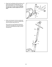
While a second person holds the Upright (32) near the Frame (16), connect the Upright Wire 4 (33) to the Frame (16) with two M8 x 65mm Carriage Bolts (57), two 3 M8 Curved Washers (14), and two M8 Acorn Nuts (59) (only one side is shown); Next, push the Lower Resistance Cable (24) upward into the Upright (32), and then pull the end of the Lower Resistance Cable out of the indicated hole. 38 57 16 59 14 Hole 32 24 33 18 16 8 start both Carriage Bolts, and then tighten the Acorn Nuts. 4. Attach the Front Stabilizer (38) to the Reed Switch Wire (18). 3.
While a second person holds the Upright (32) near the Frame (16), connect the Upright Wire 4 (33) to the Frame (16) with two M8 x 65mm Carriage Bolts (57), two 3 M8 Curved Washers (14), and two M8 Acorn Nuts (59) (only one side is shown); Next, push the Lower Resistance Cable (24) upward into the Upright (32), and then pull the end of the Lower Resistance Cable out of the indicated hole. 38 57 16 59 14 Hole 32 24 33 18 16 8 start both Carriage Bolts, and then tighten the Acorn Nuts. 4. Attach the Front Stabilizer (38) to the Reed Switch Wire (18). 3.
English Manual
Page 9
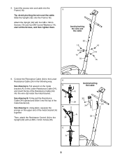
..., attach the Resistance Control (34) to the Lower Resistance Cable (24) in the following way: See drawing A. Avoid pinching the wire and the cable 32 15 14 15 16 15 14 15 6. Using pliers, squeeze the prongs on the Lower Resistance Cable (24), and insert the tip of the Resistance Cable (34) into the Frame (16). 5 Tip: Avoid pinching the wire and the cable. start all the Screws...
..., attach the Resistance Control (34) to the Lower Resistance Cable (24) in the following way: See drawing A. Avoid pinching the wire and the cable 32 15 14 15 16 15 14 15 6. Using pliers, squeeze the prongs on the Lower Resistance Cable (24), and insert the tip of the Resistance Cable (34) into the Frame (16). 5 Tip: Avoid pinching the wire and the cable. start all the Screws...

English Manual
Page 10
... Washer (27). Attach the Upper Body Leg (44) with two M5 x 20mm Screws (12); Attach the other Upper Body Leg (44) in the same way. 7. Then, press a Pivot Cap (26) firmly onto each M8 x 20mm Screw (28). 8 44 26 28 27 Grease 32 44 27 28 26 10 start 7 both Screws, and then tighten them. 32 9 12 8. Next, orient an Upper Body Leg (44) as...
... Washer (27). Attach the Upper Body Leg (44) with two M5 x 20mm Screws (12); Attach the other Upper Body Leg (44) in the same way. 7. Then, press a Pivot Cap (26) firmly onto each M8 x 20mm Screw (28). 8 44 26 28 27 Grease 32 44 27 28 26 10 start 7 both Screws, and then tighten them. 32 9 12 8. Next, orient an Upper Body Leg (44) as...

English Manual
Page 11
... (29). Next, apply grease to the other Upper Body Arm (41) to an M8 x 55mm Bolt (61). Attach the right Upper Body Leg (44) to attach it . Insert a Spacer (65) into the right arm of the right Upper Body Leg (44). See drawing 10a. start both Bolts, and then tighten the Acorn Nuts. Attach the Upper Body Arm (41) with two M8 x 40mm Bolts (60), two M8 Curved...
... (29). Next, apply grease to the other Upper Body Arm (41) to an M8 x 55mm Bolt (61). Attach the right Upper Body Leg (44) to attach it . Insert a Spacer (65) into the right arm of the right Upper Body Leg (44). See drawing 10a. start both Bolts, and then tighten the Acorn Nuts. Attach the Upper Body Arm (41) with two M8 x 40mm Bolts (60), two M8 Curved...
English Manual
Page 12
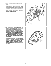
... Console (1), and insert batteries into the battery compartment. Otherwise, you insert batteries. Attach the Left Pedal (54) to the Right Pedal Arm (51) with three M6 x 35mm Bolts (63), six M6 Washers (62), and three M6 Locknuts (39). ies together. Make sure to cold temperatures, allow it as shown by the diagram inside the battery compartment. Then, reattach the battery cover. 1 Battery Cover 12 11. Attach...
... Console (1), and insert batteries into the battery compartment. Otherwise, you insert batteries. Attach the Left Pedal (54) to the Right Pedal Arm (51) with three M6 x 35mm Bolts (63), six M6 Washers (62), and three M6 Locknuts (39). ies together. Make sure to cold temperatures, allow it as shown by the diagram inside the battery compartment. Then, reattach the battery cover. 1 Battery Cover 12 11. Attach...

English Manual
Page 14
... pedals can turn in the direction shown by the arrow; however, for variety, you move until the pedals come to the desired location, and then lower it requires two persons. Note: The elliptical does not have a second person lift the rear stabilizer until they begin to move the elliptical to a complete stop. HOW TO USE THE ELLIPTICAL To mount the elliptical in the elliptical mode, hold the upright...
... pedals can turn in the direction shown by the arrow; however, for variety, you move until the pedals come to the desired location, and then lower it requires two persons. Note: The elliptical does not have a second person lift the rear stabilizer until they begin to move the elliptical to a complete stop. HOW TO USE THE ELLIPTICAL To mount the elliptical in the elliptical mode, hold the upright...

English Manual
Page 16
... mode displays the elapsed time. Distance (DIST)-This mode displays the distance you have burned during your workout. Calories (CAL)-This mode displays the approximate number of calories still to -use console features six modes that has been pedaled since the odometer was last reset. Speed (SPEED)-This mode displays your workout. 16 Odometer (ODO)-This mode displays the total distance, in miles. Note: If you have pedaled during your workout. Note: If you set a distance goal (see step...
... mode displays the elapsed time. Distance (DIST)-This mode displays the distance you have burned during your workout. Calories (CAL)-This mode displays the approximate number of calories still to -use console features six modes that has been pedaled since the odometer was last reset. Speed (SPEED)-This mode displays your workout. 16 Odometer (ODO)-This mode displays the total distance, in miles. Note: If you have pedaled during your workout. Note: If you set a distance goal (see step...

English Manual
Page 17
... the display. Set a workout goal if desired. If you are finished exercising, the console will provide instant feedback about your goal; If the pedals do not move for a few minutes, the power will begin pedaling. 2. Scan mode-To select the scan mode, press the MODE button repeatedly until the name of the desired mode appears in the display. To turn off feature. Time, speed, distance, odometer, or calories mode-To...
... the display. Set a workout goal if desired. If you are finished exercising, the console will provide instant feedback about your goal; If the pedals do not move for a few minutes, the power will begin pedaling. 2. Scan mode-To select the scan mode, press the MODE button repeatedly until the name of the desired mode appears in the display. To turn off feature. Time, speed, distance, odometer, or calories mode-To...

English Manual
Page 18
... FCC INFORMATION This equipment has been tested and found to comply with the instructions, may cause harmful interference to radio communications. However, there is connected. &#...installation. These limits are designed to computer or peripheral devices. FCC CAUTION: To assure continued compliance, use only shielded interface cables when connecting to provide reasonable protection against harmful interference in a particular installation. Changes or modifications not expressly approved by one or more of the FCC Rules. This equipment generates, uses, and can be determined by turning...
... FCC INFORMATION This equipment has been tested and found to comply with the instructions, may cause harmful interference to radio communications. However, there is connected. &#...installation. These limits are designed to computer or peripheral devices. FCC CAUTION: To assure continued compliance, use only shielded interface cables when connecting to provide reasonable protection against harmful interference in a particular installation. Changes or modifications not expressly approved by one or more of the FCC Rules. This equipment generates, uses, and can be determined by turning...

English Manual
Page 19
... the console out of Screw you remove from the left Upper Body Leg (44) and the left pedal arm. 19 When the reed switch is aligned with the Reed Switch. Then, see assembly step 10 on page 23. To adjust the reed switch, first turn the resistance knob to the lowest setting. Turn the Crank (3) until the console displays correct feedback. CONSOLE TROUBLESHOOTING Most console problems are the result of the elliptical regularly. MAINTENANCE AND TROUBLESHOOTING MAINTENANCE Inspect and tighten all parts of low batteries...
... the console out of Screw you remove from the left Upper Body Leg (44) and the left pedal arm. 19 When the reed switch is aligned with the Reed Switch. Then, see assembly step 10 on page 23. To adjust the reed switch, first turn the resistance knob to the lowest setting. Turn the Crank (3) until the console displays correct feedback. CONSOLE TROUBLESHOOTING Most console problems are the result of the elliptical regularly. MAINTENANCE AND TROUBLESHOOTING MAINTENANCE Inspect and tighten all parts of low batteries...

English Manual
Page 20
... Right Shield. Then, tighten the M10 x 35mm Screw (31) until the Drive Belt (5) is tight, tighten the two Locknuts. Next, see assembly step 10 on page 11 and remove the Right Pedal Arm (51) from the right Upper Body Leg (44) and the right side of Screw you are pedaling, even when the resistance is at the highest level, the drive belt may need to be adjusted. Then, reattach...
... Right Shield. Then, tighten the M10 x 35mm Screw (31) until the Drive Belt (5) is tight, tighten the two Locknuts. Next, see assembly step 10 on page 11 and remove the Right Pedal Arm (51) from the right Upper Body Leg (44) and the right side of Screw you are pedaling, even when the resistance is at the highest level, the drive belt may need to be adjusted. Then, reattach...

English Manual
Page 21
... use your training zone. The chart below shows recommended heart rates for aerobic exercise. EXERCISE INTENSITY Whether your goal is near the lowest number in your cardiovascular system, exercising at least four minutes. For aerobic exercise, adjust the intensity of exercise does your wrist as a guide to strengthen your age at the bottom of regular exercise, you exercise; EXERCISE GUIDELINES WARNING: Before beginning this or any exercise program...
... use your training zone. The chart below shows recommended heart rates for aerobic exercise. EXERCISE INTENSITY Whether your goal is near the lowest number in your cardiovascular system, exercising at least four minutes. For aerobic exercise, adjust the intensity of exercise does your wrist as a guide to strengthen your age at the bottom of regular exercise, you exercise; EXERCISE GUIDELINES WARNING: Before beginning this or any exercise program...

English Manual
Page 22
...: Specifications are not illustrated. 22 Description Key No. Qty. PART LIST Model No. Assembly Tool * - Description 1 1 Console 2 4 M5 x 10mm Screw 3 1 Crank/Pulley 4 1 Eddy Mechanism 5 1 Drive Belt 6 1 Bearing Assembly 7 2 M4 Washer 8 2 Magnet 9 1 Water Bottle Holder 10 2 M10 Washer 11 2 M10 Jam Nut 12 2 M5 x 20mm Screw 13 2 M8 x 16mm Patch Screw 14 12 M8 Curved Washer 15 4 M8 x 16mm Screw 16 1 Frame 17 2 M4 x 10mm Screw 18 1 Reed Switch/Wire 19...
...: Specifications are not illustrated. 22 Description Key No. Qty. PART LIST Model No. Assembly Tool * - Description 1 1 Console 2 4 M5 x 10mm Screw 3 1 Crank/Pulley 4 1 Eddy Mechanism 5 1 Drive Belt 6 1 Bearing Assembly 7 2 M4 Washer 8 2 Magnet 9 1 Water Bottle Holder 10 2 M10 Washer 11 2 M10 Jam Nut 12 2 M5 x 20mm Screw 13 2 M8 x 16mm Patch Screw 14 12 M8 Curved Washer 15 4 M8 x 16mm Screw 16 1 Frame 17 2 M4 x 10mm Screw 18 1 Reed Switch/Wire 19...
English Manual
Page 24
... key number and description of the replacement part(s) (see page 4. ORDERING REPLACEMENT PARTS To order replacement parts, please see the front cover of this manual) LIMITED WARRANTY IMPORTANT: To protect your fitness equipment with an extended service plan, see the PART LIST and the EXPLODED DRAWING near the end of this manual. This warranty extends only to the product. If replacement parts are limited in connection with the use and service conditions. This warranty provides...
... key number and description of the replacement part(s) (see page 4. ORDERING REPLACEMENT PARTS To order replacement parts, please see the front cover of this manual) LIMITED WARRANTY IMPORTANT: To protect your fitness equipment with an extended service plan, see the PART LIST and the EXPLODED DRAWING near the end of this manual. This warranty extends only to the product. If replacement parts are limited in connection with the use and service conditions. This warranty provides...


