
English Manual
Page 1
... Sat. 8 a.m.–-4 p.m. USER’'S MANUAL Keep this manual) before using this equipment. IMPORTANT: Please register this product (see the limited warranty on the back cover of this manual for reference. MT ON THE WEB: www.wesloservice.com CAUTION Read all precautions and instructions in the space above for future reference. WLEL61610.0 Serial No. If you have questions, or if parts are damaged...
... Sat. 8 a.m.–-4 p.m. USER’'S MANUAL Keep this manual) before using this equipment. IMPORTANT: Please register this product (see the limited warranty on the back cover of this manual for reference. MT ON THE WEB: www.wesloservice.com CAUTION Read all precautions and instructions in the space above for future reference. WLEL61610.0 Serial No. If you have questions, or if parts are damaged...
English Manual
Page 2
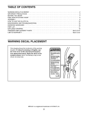
... DECAL PLACEMENT 2 IMPORTANT PRECAUTIONS 3 BEFORE YOU BEGIN 4 PART IDENTIFICATION CHART 5 ASSEMBLY 6 HOW TO USE THE ELLIPTICAL 12 MAINTENANCE AND TROUBLESHOOTING 15 EXERCISE GUIDELINES 16 PART LIST 17 EXPLODED DRAWING 18 ORDERING REPLACEMENT PARTS Back Cover LIMITED WARRANTY Back Cover WARNING DECAL PLACEMENT This drawing shows the location(s) of ICON IP, Inc. 2 WESLO is missing or illegible, see the front cover of this manual and request a free replacement decal. Apply the decal in the...
... DECAL PLACEMENT 2 IMPORTANT PRECAUTIONS 3 BEFORE YOU BEGIN 4 PART IDENTIFICATION CHART 5 ASSEMBLY 6 HOW TO USE THE ELLIPTICAL 12 MAINTENANCE AND TROUBLESHOOTING 15 EXERCISE GUIDELINES 16 PART LIST 17 EXPLODED DRAWING 18 ORDERING REPLACEMENT PARTS Back Cover LIMITED WARRANTY Back Cover WARNING DECAL PLACEMENT This drawing shows the location(s) of ICON IP, Inc. 2 WESLO is missing or illegible, see the front cover of this manual and request a free replacement decal. Apply the decal in the...
English Manual
Page 3
... experience pain while exercising, stop immediately and cool down. 3 ICON assumes no responsibility for foot protection while exercising. 11. Do not use only. Replace any exercise program, consult your pedaling speed in a garage or covered patio, or near water. 6. The elliptical does not have a freewheel; It is the responsibility of the owner to move until the flywheel stops. Wear appropriate clothes while exercising; Always wear athletic...
... experience pain while exercising, stop immediately and cool down. 3 ICON assumes no responsibility for foot protection while exercising. 11. Do not use only. Replace any exercise program, consult your pedaling speed in a garage or covered patio, or near water. 6. The elliptical does not have a freewheel; It is the responsibility of the owner to move until the flywheel stops. Wear appropriate clothes while exercising; Always wear athletic...
English Manual
Page 4
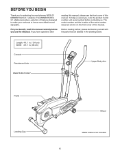
... benefit, read this manual carefully before contacting us assist you for selecting the revolutionary WESLO® MOMENTUM G 3.1 elliptical. To help us . If you use the elliptical. Length: 4 ft. 1 in. (124 cm) Width: 2 ft. 1 in the drawing below. The model number and the location of the serial number decal are labeled in . (63 cm) Console Resistance Knob Water Bottle Holder* Upper Body Arm Pedal Leveling Cap Wheel *Water...
... benefit, read this manual carefully before contacting us assist you for selecting the revolutionary WESLO® MOMENTUM G 3.1 elliptical. To help us . If you use the elliptical. Length: 4 ft. 1 in. (124 cm) Width: 2 ft. 1 in the drawing below. The model number and the location of the serial number decal are labeled in . (63 cm) Console Resistance Knob Water Bottle Holder* Upper Body Arm Pedal Leveling Cap Wheel *Water...

English Manual
Page 5
... the hardware kit, check to identify the small parts needed for assembly. The number following the key number is the key number of the part, from the PART LIST near the end of this manual. PART IDENTIFICATION CHART Use the drawings below each drawing is the quantity needed for assembly. Note: If a part is not in parentheses below to see if it has been preassembled. M4 Washer (71...
... the hardware kit, check to identify the small parts needed for assembly. The number following the key number is the key number of the part, from the PART LIST near the end of this manual. PART IDENTIFICATION CHART Use the drawings below each drawing is the quantity needed for assembly. Note: If a part is not in parentheses below to see if it has been preassembled. M4 Washer (71...
English Manual
Page 6
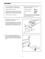
...: one Phillips screwdriver one adjustable wrench pliers Assembly may be easier if you complete all parts in a cleared area and remove the packing materials. Do not dispose of the packing materials until you have a socket set or a set of the Frame (1), attach the Front Stabilizer (10) to the 2 Frame with two M8 x 80mm Button Screws (51), two M8 Split...
...: one Phillips screwdriver one adjustable wrench pliers Assembly may be easier if you complete all parts in a cleared area and remove the packing materials. Do not dispose of the packing materials until you have a socket set or a set of the Frame (1), attach the Front Stabilizer (10) to the 2 Frame with two M8 x 80mm Button Screws (51), two M8 Split...

English Manual
Page 7
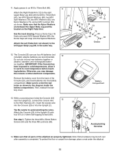
... on the Lower Cable (42) as shown. Next, connect the Resistance Cable (25) to the Reed Switch Wire (47). 3. Insert the Resistance Cable (25) through the Upright (2) as shown. •• See inset drawing C. Then, attach the 3 Resistance Control (25) to the Upright with three M8 x 20mm Button Screws (54), three M8 Split Washers (63), and three M8 Washers (55). Then, attach the Upright (2) with two M8 x 60mm Button Bolts (87...
... on the Lower Cable (42) as shown. Next, connect the Resistance Cable (25) to the Reed Switch Wire (47). 3. Insert the Resistance Cable (25) through the Upright (2) as shown. •• See inset drawing C. Then, attach the 3 Resistance Control (25) to the Upright with three M8 x 20mm Button Screws (54), three M8 Split Washers (63), and three M8 Washers (55). Then, attach the Upright (2) with two M8 x 60mm Button Bolts (87...

English Manual
Page 8
... way. 5 6 64 58 Hex Holes 55 56 64 8 Attach the Right Upper Body Arm with a sticker, and orient it as shown. 6 Next, orient an Upper Body Leg (64) so that the heads of the hexagonal holes. 5. Attach the Left Upper Body Arm (5) to the Upright (2) with two ST4.2 x 20mm Self-tapping 5 Screws (68) and two M4 Washers (71). 2 69 71...
... way. 5 6 64 58 Hex Holes 55 56 64 8 Attach the Right Upper Body Arm with a sticker, and orient it as shown. 6 Next, orient an Upper Body Leg (64) so that the heads of the hexagonal holes. 5. Attach the Left Upper Body Arm (5) to the Upright (2) with two ST4.2 x 20mm Self-tapping 5 Screws (68) and two M4 Washers (71). 2 69 71...

English Manual
Page 9
... and a Plastic Washer (27) as shown. Attach the other Outer Cover (24) to the Inner Cover (22) on the Upright (2). Attach an Outer Cover (24) to the other Inner Cover (22) in the same way. 5 2 26 74 22 Grease 6 27 72 63 57 8. Attach the Left Upper Body Arm (5) in the same way. 24 22 6... 66 22 24 66 9 Using a plastic bag to ...
... and a Plastic Washer (27) as shown. Attach the other Outer Cover (24) to the Inner Cover (22) on the Upright (2). Attach an Outer Cover (24) to the other Inner Cover (22) in the same way. 5 2 26 74 22 Grease 6 27 72 63 57 8. Attach the Left Upper Body Arm (5) in the same way. 24 22 6... 66 22 24 66 9 Using a plastic bag to ...
English Manual
Page 10
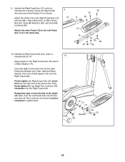
...: Turn the Left Crank Axle (not shown) and the Left Thin Locknuts (not shown) counterclockwise to the Right Pedal Arm (12) with a sticker. Orient the Right Pedal Arm and one of the elliptical. Attach the Pedal (13) to tighten them. 18 75 74 Grease 36 44 16 10 Insert the Right Crank Axle (16) into the right arm of the Crank (18). Firmly tighten the...
...: Turn the Left Crank Axle (not shown) and the Left Thin Locknuts (not shown) counterclockwise to the Right Pedal Arm (12) with a sticker. Orient the Right Pedal Arm and one of the elliptical. Attach the Pedal (13) to tighten them. 18 75 74 Grease 36 44 16 10 Insert the Right Crank Axle (16) into the right arm of the Crank (18). Firmly tighten the...
English Manual
Page 11
... Console (23), and insert batteries into the Upright (2). Insert the excess wire into the Console (23) or into the battery compartment. alkaline batteries are properly tightened. ing batteries. ies together. Remove the battery cover from damage, place a mat under the elliptical. 11 Apply grease to room temperature before insert- the Dome Caps will snap onto the Special Washers. Otherwise, you may be left Upper Body Leg...
... Console (23), and insert batteries into the Upright (2). Insert the excess wire into the Console (23) or into the battery compartment. alkaline batteries are properly tightened. ing batteries. ies together. Remove the battery cover from damage, place a mat under the elliptical. 11 Apply grease to room temperature before insert- the Dome Caps will snap onto the Special Washers. Otherwise, you may be left Upper Body Leg...
English Manual
Page 12
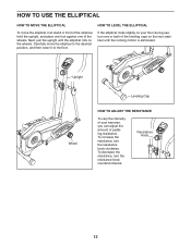
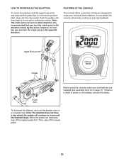
... during use, turn one of the leveling caps on the rear stabilizer until the elliptical rolls on your exercise, you can adjust the amount of pedaling resistance. Carefully move the elliptical, first stand in front of the elliptical, hold the upright, and place one foot against one or both of the wheels. To decrease the resistance, turn the resistance knob clockwise. Resistance Knob 12 Next, pull the upright until...
... during use, turn one of the leveling caps on the rear stabilizer until the elliptical rolls on your exercise, you can adjust the amount of pedaling resistance. Carefully move the elliptical, first stand in front of the elliptical, hold the upright, and place one foot against one or both of the wheels. To decrease the resistance, turn the resistance knob clockwise. Resistance Knob 12 Next, pull the upright until...
English Manual
Page 13
Note: The crank arms can turn the crank arms in either direction. It is recommended that batteries are stationary, step off the lowest pedal. 13 FEATURES OF THE CONSOLE The console offers a selection of plastic on page 11). When the pedals are installed (see assembly step 12 on the display, remove the plastic. Next, step onto the other pedal. Upper Body Arms Pedals Crank Arm Before using the console, make your workouts more effective. Then, step off the highest...
Note: The crank arms can turn the crank arms in either direction. It is recommended that batteries are stationary, step off the lowest pedal. 13 FEATURES OF THE CONSOLE The console offers a selection of plastic on page 11). When the pedals are installed (see assembly step 12 on the display, remove the plastic. Next, step onto the other pedal. Upper Body Arms Pedals Crank Arm Before using the console, make your workouts more effective. Then, step off the highest...
English Manual
Page 14
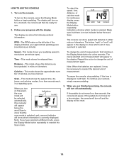
... Scan. Follow your workout, simply resume pedaling. 3. To select the speed, time, distance, or calories mode for a few seconds. Calories—-This mode shows the approximate number of calories you have burned. Scan—-This mode shows the speed, time, distance, and calories modes, for continuous display, press the Display Mode button repeatedly. HOW TO USE THE CONSOLE 1. Note: When the batteries are finished exercising, the console will then be selected...
... Scan. Follow your workout, simply resume pedaling. 3. To select the speed, time, distance, or calories mode for a few seconds. Calories—-This mode shows the approximate number of calories you have burned. Scan—-This mode shows the speed, time, distance, and calories modes, for continuous display, press the Display Mode button repeatedly. HOW TO USE THE CONSOLE 1. Note: When the batteries are finished exercising, the console will then be selected...
English Manual
Page 15
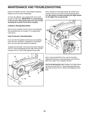
... Shield on page 11 for replacement instructions. 36 HOW TO ADJUST THE DRIVE BELT If you can feel the pedals slip while you can reach the Idler Adjustment Bolt (34). Be careful to the console, keep liquids away from the console and keep the console out of low batteries. To adjust the drive belt, first remove the three indicated ST4.2 x 12mm Self-tapping Screws (66) and the three...
... Shield on page 11 for replacement instructions. 36 HOW TO ADJUST THE DRIVE BELT If you can feel the pedals slip while you can reach the Idler Adjustment Bolt (34). Be careful to the console, keep liquids away from the console and keep the console out of low batteries. To adjust the drive belt, first remove the three indicated ST4.2 x 12mm Self-tapping Screws (66) and the three...
English Manual
Page 16
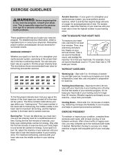
... post-exercise problems. EXERCISE FREQUENCY To maintain or improve your condition, complete three workouts each week, with your heart rate near the lowest number in your heart rate is the heart rate for maximum fat burning, and the highest number is 140 beats per minute. The chart below shows recommended heart rates for successful results. For aerobic exercise, adjust the intensity of your exercise program, do not keep your heart rate...
... post-exercise problems. EXERCISE FREQUENCY To maintain or improve your condition, complete three workouts each week, with your heart rate near the lowest number in your heart rate is the heart rate for maximum fat burning, and the highest number is 140 beats per minute. The chart below shows recommended heart rates for successful results. For aerobic exercise, adjust the intensity of your exercise program, do not keep your heart rate...

English Manual
Page 17
... Pedal Arm 12 1 Right Pedal Arm 13 2 Pedal 14 4 Dome Cap 15 1 Left Crank Axle 16 1 Right Crank Axle 17 1 Flywheel 18 1 Crank 19 1 Drive Belt 20 1 Crank Bearing Assembly 21 2 Front Stabilizer Cap 22 2 Inner Cover 23 1 Console 24 2 Outer Cover 25 1 Resistance Control/Cable 26 2 Upright Spacer 27 2 Plastic Washer 28 1 Rear Stabilizer 29 1 Large Flywheel Bearing 30 –- (Not Used) 31 1 Wire Harness 32 1 Pulley 33 2 Leveling Cap 34 1 Idler Adjustment Bolt...
... Pedal Arm 12 1 Right Pedal Arm 13 2 Pedal 14 4 Dome Cap 15 1 Left Crank Axle 16 1 Right Crank Axle 17 1 Flywheel 18 1 Crank 19 1 Drive Belt 20 1 Crank Bearing Assembly 21 2 Front Stabilizer Cap 22 2 Inner Cover 23 1 Console 24 2 Outer Cover 25 1 Resistance Control/Cable 26 2 Upright Spacer 27 2 Plastic Washer 28 1 Rear Stabilizer 29 1 Large Flywheel Bearing 30 –- (Not Used) 31 1 Wire Harness 32 1 Pulley 33 2 Leveling Cap 34 1 Idler Adjustment Bolt...
English Manual
Page 18
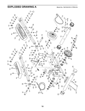
WLEL61610.0 R0912A 33 81 48 28 55 63 51 55 63 48 54 38 70 49 48 43 20 32 37 46 10 55 63 45 33 18 36 86 19 51 21 EXPLODED DRAWING A 52 13 52 14 61 60 80 78 62 61 52 14 52 53 80 78 62 15 59 44 41 62 53 42 41 74 55 58 9 75 11 55 58 79 62 13 78 80 53 14 58 75 59 74 41 35 83 39 44 12 41 55 62 78 80 60 14 55 58 58 58 55 7 85 85 39 82 84 48 43 49 34 48 62 53 48 50 43 46 29 1 16 17 20 47 21 18 Model No.
WLEL61610.0 R0912A 33 81 48 28 55 63 51 55 63 48 54 38 70 49 48 43 20 32 37 46 10 55 63 45 33 18 36 86 19 51 21 EXPLODED DRAWING A 52 13 52 14 61 60 80 78 62 61 52 14 52 53 80 78 62 15 59 44 41 62 53 42 41 74 55 58 9 75 11 55 58 79 62 13 78 80 53 14 58 75 59 74 41 35 83 39 44 12 41 55 62 78 80 60 14 55 58 58 58 55 7 85 85 39 82 84 48 43 49 34 48 62 53 48 50 43 46 29 1 16 17 20 47 21 18 Model No.

English Manual
Page 19
19 67 74 26 8 57 63 72 27 40 24 56 25 5 31 71 69 68 54 63 55 40 87 63 58 55 22 64 54 66 87 66 3 68 55 66 73 65 66 65 73 67 66 76 77 67 23 66 26 74 8 2 6 66 40 58 22 55 63 54 58 4 66 68 40 55 58 24 56 64 66 73 65 27 72 63 57 65 68 73 67 Model No. WLEL61610.0 R0912A EXPLODED DRAWING B
19 67 74 26 8 57 63 72 27 40 24 56 25 5 31 71 69 68 54 63 55 40 87 63 58 55 22 64 54 66 87 66 3 68 55 66 73 65 66 65 73 67 66 76 77 67 23 66 26 74 8 2 6 66 40 58 22 55 63 54 58 4 66 68 40 55 58 24 56 64 66 73 65 27 72 63 57 65 68 73 67 Model No. WLEL61610.0 R0912A EXPLODED DRAWING B
English Manual
Page 20
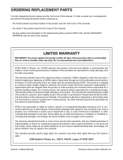
..., the above is limited to provide the following information when contacting us: •• the model number and serial number of the product (see the front cover of this manual) •• the name of the product (see the front cover of this manual) •• the key number and description of the replacement part(s) (see the front cover of this manual. This warranty provides specific legal rights;
..., the above is limited to provide the following information when contacting us: •• the model number and serial number of the product (see the front cover of this manual) •• the name of the product (see the front cover of this manual) •• the key number and description of the replacement part(s) (see the front cover of this manual. This warranty provides specific legal rights;


