
Uk Manual
Page 1
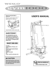
[email protected] CAUTION Read all precautions and instructions in the space above for future reference. Serial Number Decal (under seat) QUESTIONS? As a manufacturer, we are missing or damaged parts, please call: 08457 089 009 Or write: ICON Health & Fitness, Ltd. USER'S MANUAL Visit our website at www.iconeurope.com Save this equipment. Model No.WLEVSY98110 Serial No. If you have questions, or if...
[email protected] CAUTION Read all precautions and instructions in the space above for future reference. Serial Number Decal (under seat) QUESTIONS? As a manufacturer, we are missing or damaged parts, please call: 08457 089 009 Or write: ICON Health & Fitness, Ltd. USER'S MANUAL Visit our website at www.iconeurope.com Save this equipment. Model No.WLEVSY98110 Serial No. If you have questions, or if...
Uk Manual
Page 2
WESLO is attached in the centre of ICON Health & Fitness, Inc. 2 TABLE OF CONTENTS IMPORTANT PRECAUTIONS 3 BEFORE YOU BEGIN 4 ASSEMBLY 5 ADJUSTMENT 15 WEIGHT RESISTANCE CHART 17 TROUBLESHOOTING AND MAINTENANCE 18 CABLE DIAGRAM 19 PART LIST 22 EXPLODED DRAWING 23 ORDERING REPLACEMENT PARTS Back Cover Note: A PART IDENTIFICATION CHART is a registered trademark of this manual. Remove the PART IDENTIFICATION CHART before beginning assembly.
WESLO is attached in the centre of ICON Health & Fitness, Inc. 2 TABLE OF CONTENTS IMPORTANT PRECAUTIONS 3 BEFORE YOU BEGIN 4 ASSEMBLY 5 ADJUSTMENT 15 WEIGHT RESISTANCE CHART 17 TROUBLESHOOTING AND MAINTENANCE 18 CABLE DIAGRAM 19 PART LIST 22 EXPLODED DRAWING 23 ORDERING REPLACEMENT PARTS Back Cover Note: A PART IDENTIFICATION CHART is a registered trademark of this manual. Remove the PART IDENTIFICATION CHART before beginning assembly.
Uk Manual
Page 3
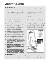
... for home use the lat bar. 14. This is the responsibility of the owner to support a maximum user weight of 114 kg (250 lbs.). Replace any exercise program, consult your physician. If the decal is designed to ensure that the cables remain on the foot plate when performing an exercise that does not use only. Never release the press arm, butterfly arms, leg lever, lat bar, or nylon strap whilst weights are exercising, stop...
... for home use the lat bar. 14. This is the responsibility of the owner to support a maximum user weight of 114 kg (250 lbs.). Replace any exercise program, consult your physician. If the decal is designed to ensure that the cables remain on the foot plate when performing an exercise that does not use only. Never release the press arm, butterfly arms, leg lever, lat bar, or nylon strap whilst weights are exercising, stop...
Uk Manual
Page 4
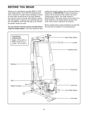
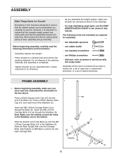
... serial number can be found on a decal attached to develop every major muscle group of this owner's manual for selecting the versatile WESLO® GYM 1000 weight system. The GYM 1000 weight system offers a selection of weight stations designed to the weight system (see the front cover of the body. Before reading further, please familiarise yourself with the parts that are labelled in .) High Pulley Station Lat Bar Butterfly Arms Backrest Seat Weight...
... serial number can be found on a decal attached to develop every major muscle group of this owner's manual for selecting the versatile WESLO® GYM 1000 weight system. The GYM 1000 weight system offers a selection of weight stations designed to the weight system (see the front cover of the body. Before reading further, please familiarise yourself with the parts that are labelled in .) High Pulley Station Lat Bar Butterfly Arms Backrest Seat Weight...
Uk Manual
Page 5
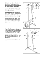
... you have a socket set, a set of open-end or closed-end wrenches, or a set of ratchet wrenches. FRAME ASSEMBLY 1 1. The following information and instructions: • Assembly requires two people. • Place all parts are oriented as shown in the drawings. • For help identifying small parts, use the PART IDENTIFICATION CHART in the Stabiliser (5). Insert two M8 x 67mm Carriage Bolts (14) up through the...
... you have a socket set, a set of open-end or closed-end wrenches, or a set of ratchet wrenches. FRAME ASSEMBLY 1 1. The following information and instructions: • Assembly requires two people. • Place all parts are oriented as shown in the drawings. • For help identifying small parts, use the PART IDENTIFICATION CHART in the Stabiliser (5). Insert two M8 x 67mm Carriage Bolts (14) up through the...
Uk Manual
Page 6
...). Attach the Weight Stop (67) to the Front Upright (42) with an M8 x 70mm Bolt (11) and an M8 Nylon Locknut (3). Orient the Weight Carriage (19) as shown. Press a 45mm Square Inner Cap (44) into each Carriage Bolt. Slide the Weight Stop onto the Rear Upright (56). Hand tighten an M8 Nylon Locknut (3) onto each end of the crossbar. Tighten the Nylon Locknuts (3) used in...
...). Attach the Weight Stop (67) to the Front Upright (42) with an M8 x 70mm Bolt (11) and an M8 Nylon Locknut (3). Orient the Weight Carriage (19) as shown. Press a 45mm Square Inner Cap (44) into each Carriage Bolt. Slide the Weight Stop onto the Rear Upright (56). Hand tighten an M8 Nylon Locknut (3) onto each end of the crossbar. Tighten the Nylon Locknuts (3) used in...
Uk Manual
Page 7
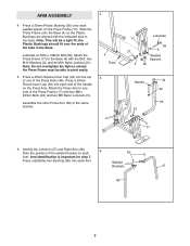
... fit over the ends of the Press Frame (17) with the Bolt, two M10 Washers (9), and an M10 Nylon Locknut (21). Attach the Press Arm to pivot easily. 5. Arm identification is important for step 7. Note: Do not overtighten the Nylon Locknut; Note: This will be able to one of the welded bracket on each welded spacer on the Press Arm. Assemble...
... fit over the ends of the Press Frame (17) with the Bolt, two M10 Washers (9), and an M10 Nylon Locknut (21). Attach the Press Arm to pivot easily. 5. Arm identification is important for step 7. Note: Do not overtighten the Nylon Locknut; Note: This will be able to one of the welded bracket on each welded spacer on the Press Arm. Assemble...
Uk Manual
Page 8
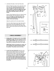
...). Wet the lower end of the Cable with soapy water. Note: The small tabs on the Pulley Covers must turn freely. 8 23 58 55 47 Bracket Lubricate Axle 63 62 45 55 63 62 9. Attach the 9 Pulley and two Pulley Covers (73) to verify proper cable routing. 7. Make sure that the Cable is behind the indicated bracket on top. Attach the Left Arm (47) in...
...). Wet the lower end of the Cable with soapy water. Note: The small tabs on the Pulley Covers must turn freely. 8 23 58 55 47 Bracket Lubricate Axle 63 62 45 55 63 62 9. Attach the 9 Pulley and two Pulley Covers (73) to verify proper cable routing. 7. Make sure that the Cable is behind the indicated bracket on top. Attach the Left Arm (47) in...
Uk Manual
Page 9
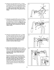
... on the Front Upright (42) with an M8 x 115mm Bolt (64) and an M8 Nylon Locknut (3). Attach the Pulley and a Long Cable Trap (50) 11 to the Pulley Bracket (20). Route the Long Cable (58) around a "V"-Pulley (6). Make sure that the Cable is in the groove of the Pulley and that the Cable Trap (66) is properly tightened and that the Cable Trap is...
... on the Front Upright (42) with an M8 x 115mm Bolt (64) and an M8 Nylon Locknut (3). Attach the Pulley and a Long Cable Trap (50) 11 to the Pulley Bracket (20). Route the Long Cable (58) around a "V"-Pulley (6). Make sure that the Cable is in the groove of the Pulley and that the Cable Trap (66) is properly tightened and that the Cable Trap is...
Uk Manual
Page 11
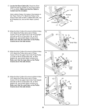
... on the side shown. 42 73 21 9 23 15 73 16 Small Tabs 11 Attach the Pulley and a pair of Pulley 20 Covers (73) to the lower hole in the Press Frame (17) with an M10 x 198mm Bolt (59), two M10 Washers (9), and an M10 Nylon Locknut (21). 17 21 9 Crossbar 17 9 ... and an M10 Nylon Locknut (21). Locate the Short Cable (23). Attach the Pulley and a pair of the bracket on the Press Frame (17), as shown. Make sure that the Cable is routed over the crossbar. Attach the Pulley to the upper hole in the Front Upright (42) with an M10 x 97mm Bolt (16), an M10 Washer (9), and...
... on the side shown. 42 73 21 9 23 15 73 16 Small Tabs 11 Attach the Pulley and a pair of Pulley 20 Covers (73) to the lower hole in the Press Frame (17) with an M10 x 198mm Bolt (59), two M10 Washers (9), and an M10 Nylon Locknut (21). 17 21 9 Crossbar 17 9 ... and an M10 Nylon Locknut (21). Locate the Short Cable (23). Attach the Pulley and a pair of the bracket on the Press Frame (17), as shown. Make sure that the Cable is routed over the crossbar. Attach the Pulley to the upper hole in the Front Upright (42) with an M10 x 97mm Bolt (16), an M10 Washer (9), and...
Uk Manual
Page 12
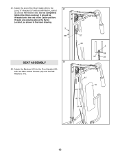
Attach the Backrest (41) to the 21 Long "U"-Bracket (57) with two M6 x 63mm Screws (43) and two M6 Washers (10). 57 23 3 68 57 23 42 41 43 10 12 it should be threaded onto the end of the Short Cable (23) to the Front Upright (42) with an M8 Nylon Locknut (3) and an M8 Washer (68). Attach the end of the Cable until two threads are showing above the Nylon Locknut, as shown in the inset drawing. 3 68 SEAT ASSEMBLY 22 22. 21. Do not completely tighten the Nylon Locknut;
Attach the Backrest (41) to the 21 Long "U"-Bracket (57) with two M6 x 63mm Screws (43) and two M6 Washers (10). 57 23 3 68 57 23 42 41 43 10 12 it should be threaded onto the end of the Short Cable (23) to the Front Upright (42) with an M8 Nylon Locknut (3) and an M8 Washer (68). Attach the end of the Cable until two threads are showing above the Nylon Locknut, as shown in the inset drawing. 3 68 SEAT ASSEMBLY 22 22. 21. Do not completely tighten the Nylon Locknut;
Uk Manual
Page 13
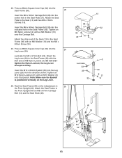
... the M6 x 50mm Carriage Bolt (38) into the Leg Lever (29) from the direction shown. Attach the Seat Frame to the Seat Frame (36) with an M8 x 67mm Carriage Bolt (14) and the Seat Knob (40). 13 38 37 32 18 36 24 10 2 36 Lubricate 33 35 32 3 29 9 21 14 Pin 42 40 36 13 Press a 38mm Square Inner Cap...
... the M6 x 50mm Carriage Bolt (38) into the Leg Lever (29) from the direction shown. Attach the Seat Frame to the Seat Frame (36) with an M8 x 67mm Carriage Bolt (14) and the Seat Knob (40). 13 38 37 32 18 36 24 10 2 36 Lubricate 33 35 32 3 29 9 21 14 Pin 42 40 36 13 Press a 38mm Square Inner Cap...
Uk Manual
Page 14
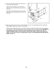
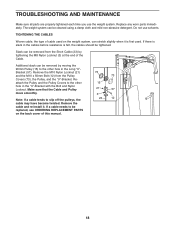
...cables move smoothly, find and correct the problem. Before using the weight system, pull each end of the Pad Tube. 36 30 34 28 34 30 29 27. IMPORTANT: If the cables are not properly routed, they may be explained in the cables, you will need to make sure that all remaining parts...of the Pad Tube. see TROUBLESHOOTING AND MAINTENANCE on page 19 of the cables does not move smoothly over the pulleys. See the CABLE DIAGRAM on page 18. 14 If there is used. Slide a Foam Pad (30) onto each cable a few times to remove it by tightening the cables; Press two 19mm Round Inner Caps...
...cables move smoothly, find and correct the problem. Before using the weight system, pull each end of the Pad Tube. 36 30 34 28 34 30 29 27. IMPORTANT: If the cables are not properly routed, they may be explained in the cables, you will need to make sure that all remaining parts...of the Pad Tube. see TROUBLESHOOTING AND MAINTENANCE on page 19 of the cables does not move smoothly over the pulleys. See the CABLE DIAGRAM on page 18. 14 If there is used. Slide a Foam Pad (30) onto each cable a few times to remove it by tightening the cables; Press two 19mm Round Inner Caps...
Uk Manual
Page 15
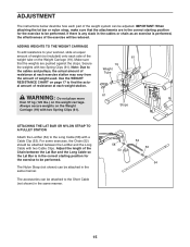
... be attached in the same manner. 58 53 52 53 54 15 The accessories can be reduced. ADJUSTMENT The instructions below describe how each part of the weight system can be performed. IMPORTANT: When attaching the lat bar or nylon strap, make sure that the weights are in the correct starting position for the exercise to be performed. Use the WEIGHT RESISTANCE CHART on the weight carriage...
... be attached in the same manner. 58 53 52 53 54 15 The accessories can be reduced. ADJUSTMENT The instructions below describe how each part of the weight system can be performed. IMPORTANT: When attaching the lat bar or nylon strap, make sure that the weights are in the correct starting position for the exercise to be performed. Use the WEIGHT RESISTANCE CHART on the weight carriage...
Uk Manual
Page 16
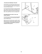
...). Attach the Seat Frame to the Short Cable (23) with a Cable Clip. Note: Make sure the Eyebolt is not attached to the M10 x 63mm Eyebolt (35) with the M8 x 67mm Carriage Bolt (14) and the Seat Knob (40). Attach the other end of the Chain (52) to the leg lever. ATTACHING AND REMOVING THE SEAT Set the bracket on the Seat Frame (36) onto the pin...
...). Attach the Seat Frame to the Short Cable (23) with a Cable Clip. Note: Make sure the Eyebolt is not attached to the M10 x 63mm Eyebolt (35) with the M8 x 67mm Carriage Bolt (14) and the Seat Knob (40). Attach the other end of the Chain (52) to the leg lever. ATTACHING AND REMOVING THE SEAT Set the bracket on the Seat Frame (36) onto the pin...
Uk Manual
Page 17
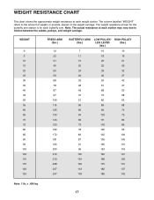
...WEIGHT" refers to friction between the cables, pulleys, and weight carriage. The weight resistance shown for the butterfly arm station is for each station may vary due to the amount of weight, in pounds, placed on the weight carriage. Note: The actual resistance at each weight station. WEIGHT...PRESS ARM (lbs.) 12 22 31 40 50 59 68 78 87 97 106 115 125 134 144 153 162 172 181 190 200 210 219 228 237 247 BUTTERFLY ARM (lbs.) LOW PULLEY/ LEG LEVER (lbs.) HIGH PULLEY... lb. = .454 kg 17 WEIGHT RESISTANCE CHART This chart shows the approximate weight resistance at each butterfly arm.
...WEIGHT" refers to friction between the cables, pulleys, and weight carriage. The weight resistance shown for the butterfly arm station is for each station may vary due to the amount of weight, in pounds, placed on the weight carriage. Note: The actual resistance at each weight station. WEIGHT...PRESS ARM (lbs.) 12 22 31 40 50 59 68 78 87 97 106 115 125 134 144 153 162 172 181 190 200 210 219 228 237 247 BUTTERFLY ARM (lbs.) LOW PULLEY/ LEG LEVER (lbs.) HIGH PULLEY... lb. = .454 kg 17 WEIGHT RESISTANCE CHART This chart shows the approximate weight resistance at each butterfly arm.
Uk Manual
Page 18
... weight system can be tightened. If there is slack in the cables before resistance is first used. Reattach the Pulley and the Pulley Covers to slip off the pulleys, the cable may have become twisted. Note: If a cable tends to the other hole in the "U"-Bracket with the Bolt and Nylon Locknut. Do not use the weight system. Make sure that the Cable and Pulley move smoothly. If a cable needs...
... weight system can be tightened. If there is slack in the cables before resistance is first used. Reattach the Pulley and the Pulley Covers to slip off the pulleys, the cable may have become twisted. Note: If a cable tends to the other hole in the "U"-Bracket with the Bolt and Nylon Locknut. Do not use the weight system. Make sure that the Cable and Pulley move smoothly. If a cable needs...

Uk Manual
Page 19
... cable traps have not been correctly routed, the weight system will not function properly and damage may occur. The starting and ending points of each cable. If the cables have been assembled correctly. Use the diagram to make sure that the cable traps do not touch or bind the cables. 2 7 5 1-High Pulley 3 4 Long Cable (58) TOP VIEW 6 5-Long "U"-Bracket Short Cable (23) Weight Carriage-8 4 3 1-Low Pulley...
... cable traps have not been correctly routed, the weight system will not function properly and damage may occur. The starting and ending points of each cable. If the cables have been assembled correctly. Use the diagram to make sure that the cable traps do not touch or bind the cables. 2 7 5 1-High Pulley 3 4 Long Cable (58) TOP VIEW 6 5-Long "U"-Bracket Short Cable (23) Weight Carriage-8 4 3 1-Low Pulley...

Uk Manual
Page 22
... Bolt 60 2 Butterfly Arm Bushing 61 2 Spring Clip 62 2 25mm Round Cover Cap 63 4 25mm Retainer 64 1 M8 x 115mm Bolt 65 1 25mm Square Inner Cap 66 1 Cable Trap 67 1 Weight Stop 68 1 M8 Washer 69 1 M10 x 20mm Bolt 70 3 Square Slider Bushing 71 2 M10 x 45mm Bolt 72 4 M8 x 67mm Bolt 73 10 Pulley Cover # 1 Userʼs Manual Note: "#" indicates a non-illustrated part. WLEVSY98110 R0702A Key No. PART LIST-Model...
... Bolt 60 2 Butterfly Arm Bushing 61 2 Spring Clip 62 2 25mm Round Cover Cap 63 4 25mm Retainer 64 1 M8 x 115mm Bolt 65 1 25mm Square Inner Cap 66 1 Cable Trap 67 1 Weight Stop 68 1 M8 Washer 69 1 M10 x 20mm Bolt 70 3 Square Slider Bushing 71 2 M10 x 45mm Bolt 72 4 M8 x 67mm Bolt 73 10 Pulley Cover # 1 Userʼs Manual Note: "#" indicates a non-illustrated part. WLEVSY98110 R0702A Key No. PART LIST-Model...
Uk Manual
Page 27
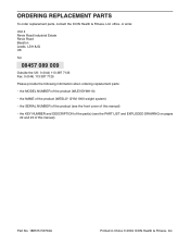
... MODEL NUMBER of the product (WLEVSY98110) • the NAME of the product (WESLO® GYM 1000 weight system) • the SERIAL NUMBER of the product (see the front cover of this manual) • the KEY NUMBER and DESCRIPTION of the part(s) (see the PART LIST and EXPLODED DRAWING on pages 22 and 23 of this manual). Part No. 188515 R0702A Printed in China © 2002 ICON Health & Fitness, Inc. ORDERING REPLACEMENT PARTS...
... MODEL NUMBER of the product (WLEVSY98110) • the NAME of the product (WESLO® GYM 1000 weight system) • the SERIAL NUMBER of the product (see the front cover of this manual) • the KEY NUMBER and DESCRIPTION of the part(s) (see the PART LIST and EXPLODED DRAWING on pages 22 and 23 of this manual). Part No. 188515 R0702A Printed in China © 2002 ICON Health & Fitness, Inc. ORDERING REPLACEMENT PARTS...


