

English Manual
Page 2
Table of Contents Limited Warranty 2 Important Precautions 3 Before You Begin 4 Assembly 5 Cable Diagram 16 Adjustment 17 Weight Resistance Chart 18 Trouble-shooting and Maintenance 19 Ordering Replacement Parts Back Cover Note: A PART LIST/EXPLODED DRAWING and a PART IDENTIFICATION CHART...Some states do not allow limitations on how long an implied warranty lasts. ICON HEALTH & FITNESS, INC., 1500 S. 1000 W., LOGAN, UT 84321-9813 WEIDER is in its scope and duration to you. Limited Warranty ICON Health & Fitness, Inc. (ICON), warrants this product to any and all freight and other...
Table of Contents Limited Warranty 2 Important Precautions 3 Before You Begin 4 Assembly 5 Cable Diagram 16 Adjustment 17 Weight Resistance Chart 18 Trouble-shooting and Maintenance 19 Ordering Replacement Parts Back Cover Note: A PART LIST/EXPLODED DRAWING and a PART IDENTIFICATION CHART...Some states do not allow limitations on how long an implied warranty lasts. ICON HEALTH & FITNESS, INC., 1500 S. 1000 W., LOGAN, UT 84321-9813 WEIDER is in its scope and duration to you. Limited Warranty ICON Health & Fitness, Inc. (ICON), warrants this product to any and all freight and other...
English Manual
Page 3
.... The training system is especially important for home use of this product. 3 WARNING: Before beginning this manual and in a commercial, rental or institutional setting. The weights will fall with pre-existing health problems. Read all users of the training system are on the foot plate when performing an exercise that does... tighten all times. It is designed to tip. 12. Never release the press arm, butterfly arms, leg lever, lat bar, row bar or handle while weights are exercising, stop immediately and begin cooling down. 9.
.... The training system is especially important for home use of this product. 3 WARNING: Before beginning this manual and in a commercial, rental or institutional setting. The weights will fall with pre-existing health problems. Read all users of the training system are on the foot plate when performing an exercise that does... tighten all times. It is designed to tip. 12. Never release the press arm, butterfly arms, leg lever, lat bar, row bar or handle while weights are exercising, stop immediately and begin cooling down. 9.
English Manual
Page 4
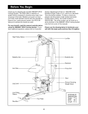
...toll-free at 1-800-999-3756, Monday through Friday, 6 a.m. If you for selecting the versatile WEIDER¨ XP23 Training System. Width: 38 in . The XP23 offers a selection of weight stations designed to develop every major muscle group of this manual carefully before calling. Whether your goal is...be found on a decal attached to achieve the results you , please note the product model number and serial number before using the WEIDER¨ XP23 Training System. Please use the drawing below to tone your body, build dramatic muscle size and strength or improve your benefit...
...toll-free at 1-800-999-3756, Monday through Friday, 6 a.m. If you for selecting the versatile WEIDER¨ XP23 Training System. Width: 38 in . The XP23 offers a selection of weight stations designed to develop every major muscle group of this manual carefully before calling. Whether your goal is...be found on a decal attached to achieve the results you , please note the product model number and serial number before using the WEIDER¨ XP23 Training System. Please use the drawing below to tone your body, build dramatic muscle size and strength or improve your benefit...

English Manual
Page 5
... that assembly stage. Place all parts as you open the packages for Yourself Everything in the center of this manual is a sophisticated product with the weights. The seats and all parts are exercising. 5 Note: Some small parts may want to ensure that you operate while you identify the small parts used...
... that assembly stage. Place all parts as you open the packages for Yourself Everything in the center of this manual is a sophisticated product with the weights. The seats and all parts are exercising. 5 Note: Some small parts may want to ensure that you operate while you identify the small parts used...

English Manual
Page 7
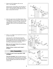
...on the Front Upright (42). Slide two 5/16Ó Flat Washers (56) onto two 6 5/16Ó x 2 3/4Ó Bolts (67). Slide eight Weights (26) onto the Weight Guides (23). Pin 25 Lubricate the insides of the holes in the Base (8). Insert the 5/16Ó x 2 3/4Ó Bolts (67) through the...stack of the Front Upright (42) and align the indicated holes with the indicated holes. 23 Insert both Weight Guides (23) through the Top Frame (1) and the bracket (C) on top of Weights (26). 4. Set four Weight Bumpers (19) onto the Base (8) and 4 align them with the holes in the ...
...on the Front Upright (42). Slide two 5/16Ó Flat Washers (56) onto two 6 5/16Ó x 2 3/4Ó Bolts (67). Slide eight Weights (26) onto the Weight Guides (23). Pin 25 Lubricate the insides of the holes in the Base (8). Insert the 5/16Ó x 2 3/4Ó Bolts (67) through the...stack of the Front Upright (42) and align the indicated holes with the indicated holes. 23 Insert both Weight Guides (23) through the Top Frame (1) and the bracket (C) on top of Weights (26). 4. Set four Weight Bumpers (19) onto the Base (8) and 4 align them with the holes in the ...
English Manual
Page 8
... 56 1 with the tube (F) on the Seat Frame (36) over the two Bolts. Press a 1 1/2Ó Square Inner Cap (33) into the end of the Weight Guides (23) to the Base with two 5/16Ó x D 1 1/2Ó Bolts (61) and two 5/16Ó Nylon Locknuts (53). Locate and open the parts bag... Insert the 5/16Ó x 1 3/4Ó Bolts (58) and hand tighten two 5/16Ó Nylon Locknuts (53) onto them since this may damage the weight guides. 61 23 53 1 9. Place the mounting bracket (E) on the Base (8). Align the holes in the bracket on the Top Frame (1) with the Bolt and a 3/8Ó...
... 56 1 with the tube (F) on the Seat Frame (36) over the two Bolts. Press a 1 1/2Ó Square Inner Cap (33) into the end of the Weight Guides (23) to the Base with two 5/16Ó x D 1 1/2Ó Bolts (61) and two 5/16Ó Nylon Locknuts (53). Locate and open the parts bag... Insert the 5/16Ó x 1 3/4Ó Bolts (58) and hand tighten two 5/16Ó Nylon Locknuts (53) onto them since this may damage the weight guides. 61 23 53 1 9. Place the mounting bracket (E) on the Base (8). Align the holes in the bracket on the Top Frame (1) with the Bolt and a 3/8Ó...
English Manual
Page 12
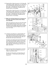
... Washer (55) and a 3/8Ó Nylon Jamnut (57). 22 66 54 23. Make sure the Bolt (62) is inserted from the 9 direction shown on the drawing. It will be necessary to lift the Weight Tube and the Top Weight 58 to the Weight Tube (25) with the 5/16Ó x 1 3/4Ó 25 Bolt ...(40) in the direction shown. Wrap the Short Cable (9) around a 3 1/2Ó Pulley (35) 20 in the direction shown. Thread the Long Cable (2) through the Weight Tube and the loop on the Base (8) with a 3/8Ó x 2Ó Bolt (62) and a 3/8Ó Nylon Locknut 62 (63). Re-attach the Pulley (35...
... Washer (55) and a 3/8Ó Nylon Jamnut (57). 22 66 54 23. Make sure the Bolt (62) is inserted from the 9 direction shown on the drawing. It will be necessary to lift the Weight Tube and the Top Weight 58 to the Weight Tube (25) with the 5/16Ó x 1 3/4Ó 25 Bolt ...(40) in the direction shown. Wrap the Short Cable (9) around a 3 1/2Ó Pulley (35) 20 in the direction shown. Thread the Long Cable (2) through the Weight Tube and the loop on the Base (8) with a 3/8Ó x 2Ó Bolt (62) and a 3/8Ó Nylon Locknut 62 (63). Re-attach the Pulley (35...

English Manual
Page 15
.... Slide the Curl Post (10) onto the Seat Frame (36) so 72 each Pad 31 Tube (28). If one with the opening for adjusting the Weights. Attach the Curl Pad (24) to remove the slack by tightening the cables. If there is any slack in ADJUSTMENT, beginning on page 17 of... the welded brackets are not properly installed, they may be explained in the cables, you will be damaged when heavy weight is the one of the #8 x 1/2Ó Tap Screws (7). 33 7 18 7 78 1 42 34. 31. Insert one Pad Tube into each of this manual. Insert the...
.... Slide the Curl Post (10) onto the Seat Frame (36) so 72 each Pad 31 Tube (28). If one with the opening for adjusting the Weights. Attach the Curl Pad (24) to remove the slack by tightening the cables. If there is any slack in ADJUSTMENT, beginning on page 17 of... the welded brackets are not properly installed, they may be explained in the cables, you will be damaged when heavy weight is the one of the #8 x 1/2Ó Tap Screws (7). 33 7 18 7 78 1 42 34. 31. Insert one Pad Tube into each of this manual. Insert the...
English Manual
Page 16
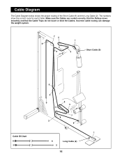
Incorrect cable routing can damage the weight system. 72 1 8 4 5 3 Short Cable (9) Cable ID Chart 6 3 9 4 6 5 7 8 2 9 1 9 2 Long Cable (2) 16 Cable Diagram The Cable Diagram below shows the proper routing of the Short Cable (9) and the Long Cable (2). Make sure the Cables are routed correctly, that the Pulleys move smoothly and that the Cable Traps do not touch or bind the Cables. The numbers show the correct route for each Cable.
Incorrect cable routing can damage the weight system. 72 1 8 4 5 3 Short Cable (9) Cable ID Chart 6 3 9 4 6 5 7 8 2 9 1 9 2 Long Cable (2) 16 Cable Diagram The Cable Diagram below shows the proper routing of the Short Cable (9) and the Long Cable (2). Make sure the Cables are routed correctly, that the Pulleys move smoothly and that the Cable Traps do not touch or bind the Cables. The numbers show the correct route for each Cable.
English Manual
Page 17
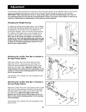
...with a Cable Clip (73). The Row Bar (70) or Handle (75) can be changed from the 39 weight setting. The Row Bar (70) or Handle (75) can be adjusted. Be sure to 106 pounds, in increments...the same manner. 17 9 73 75 74 76 70 2 74 70 73 75 76 Changing the Weight Setting To change the setting of resis- For some exercises, the Chain (74) should be performed. Then...the lat bar or nylon strap, make sure that the attachments are in the correct starting position for each weight station. 26 Attaching the Lat Bar, Row Bar or Handle to the High Pulley Station Attach the Lat ...
...with a Cable Clip (73). The Row Bar (70) or Handle (75) can be changed from the 39 weight setting. The Row Bar (70) or Handle (75) can be adjusted. Be sure to 106 pounds, in increments...the same manner. 17 9 73 75 74 76 70 2 74 70 73 75 76 Changing the Weight Setting To change the setting of resis- For some exercises, the Chain (74) should be performed. Then...the lat bar or nylon strap, make sure that the attachments are in the correct starting position for each weight station. 26 Attaching the Lat Bar, Row Bar or Handle to the High Pulley Station Attach the Lat ...
English Manual
Page 18
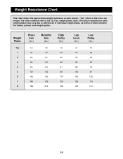
weight plates. Weight Plates Top 1 2 3 4 5 6 7 8 Press Arm (lbs.) 12 40 62 86 94 127 150 160 193 Butterfly Arm (lbs.) 46 70 97 110 141 162 180 199 ... other numbers refer to the 12.5 lbs. Note: The actual resistance at each weight station may vary due to differences in individual weight plates, as well as friction between the cables, pulleys, and weight guides. Weight Resistance Chart This chart shows the approximate weight resistance at each station. ÒTopÓ refers to the 6 lbs.
weight plates. Weight Plates Top 1 2 3 4 5 6 7 8 Press Arm (lbs.) 12 40 62 86 94 127 150 160 193 Butterfly Arm (lbs.) 46 70 97 110 141 162 180 199 ... other numbers refer to the 12.5 lbs. Note: The actual resistance at each weight station may vary due to differences in individual weight plates, as well as friction between the cables, pulleys, and weight guides. Weight Resistance Chart This chart shows the approximate weight resistance at each station. ÒTopÓ refers to the 6 lbs.

English Manual
Page 19
...slack in the bracket (P) on the home gym system, can be removed by moving the Weight Pin. To tighten the Cables, insert the Weight Pin (39, not shown) between the third and the fourth Weight, counting from turning. 44 29 32 Additional slack can stretch slightly when it is felt,...this , remove the 3/8Ó x 3 1/4Ó Bolt (69), Cable Trap (66), 3/8Ó Flat Washer (55) and 3/8Ó Nylon Locknut (63). See ÒChanging the Weight SettingÓ on page 17 for instructions on the back cover of turns until the Cables feel tighter. To do this manual. 1 P 63 55 6 69...
...slack in the bracket (P) on the home gym system, can be removed by moving the Weight Pin. To tighten the Cables, insert the Weight Pin (39, not shown) between the third and the fourth Weight, counting from turning. 44 29 32 Additional slack can stretch slightly when it is felt,...this , remove the 3/8Ó x 3 1/4Ó Bolt (69), Cable Trap (66), 3/8Ó Flat Washer (55) and 3/8Ó Nylon Locknut (63). See ÒChanging the Weight SettingÓ on page 17 for instructions on the back cover of turns until the Cables feel tighter. To do this manual. 1 P 63 55 6 69...

English Manual
Page 21
...1 3/4Ó Bolt 3/8Ó x 8Ó Bolt 3/8Ó x 1 1/2Ó Bolt 5/16Ó x 1 1/2Ó Bolt 3/8Ó x 2Ó Bolt 3/8Ó Nylon Locknut Weight Tube Bumper 3/8Ó x 2 1/4Ó Bolt Cable Trap 5/16Ó x 2 3/4Ó Bolt 1/2Ó Nylon Locknut 3/8Ó x 3 1/4Ó Bolt Row Bar 1/4Ó x... 1 3 2 4 4 5 1 6 2 7 28 8 1 9 1 10 1 11 1 12 1 13 1 14 2 15 2 16 1 17 4 18 1 19 4 20 1 21 7 22 1 23 2 24 1 25 1 26 8 27 1 28 2 29 1 30 4 31 2 32 1 33 2 34 4 35 13 36 1 37 1 38 1 39 1 40 1 41 1 42 1 43 2 ...
...1 3/4Ó Bolt 3/8Ó x 8Ó Bolt 3/8Ó x 1 1/2Ó Bolt 5/16Ó x 1 1/2Ó Bolt 3/8Ó x 2Ó Bolt 3/8Ó Nylon Locknut Weight Tube Bumper 3/8Ó x 2 1/4Ó Bolt Cable Trap 5/16Ó x 2 3/4Ó Bolt 1/2Ó Nylon Locknut 3/8Ó x 3 1/4Ó Bolt Row Bar 1/4Ó x... 1 3 2 4 4 5 1 6 2 7 28 8 1 9 1 10 1 11 1 12 1 13 1 14 2 15 2 16 1 17 4 18 1 19 4 20 1 21 7 22 1 23 2 24 1 25 1 26 8 27 1 28 2 29 1 30 4 31 2 32 1 33 2 34 4 35 13 36 1 37 1 38 1 39 1 40 1 41 1 42 1 43 2 ...


