

English Manual
Page 1
... TOLL-FREE CUSTOMER HOT LINE. MST CAUTION Read all precautions and instructions in this manual before using this manual for future reference. ¨ USERÕS MANUAL PATENT PENDING Save this equipment. If you . The trained technicians on our customer hot line will guarantee complete satisfaction through direct assistance from our factory. Write the serial number in the location shown below. The serial number is...
... TOLL-FREE CUSTOMER HOT LINE. MST CAUTION Read all precautions and instructions in this manual before using this manual for future reference. ¨ USERÕS MANUAL PATENT PENDING Save this equipment. If you . The trained technicians on our customer hot line will guarantee complete satisfaction through direct assistance from our factory. Write the serial number in the location shown below. The serial number is...

English Manual
Page 2
..., accompanied by or attributable to the original purchaser. Table of Contents Limited Warranty 2 Important Precautions 3 Before You Begin 4 Assembly 5 Cable Diagram 16 Adjustment 17 Weight Resistance Chart 18 Trouble-shooting and Maintenance 19 Ordering Replacement Parts Back Cover Note: A PART LIST/EXPLODED DRAWING and a PART IDENTIFICATION CHART are attached to the center of incidental or consequential damages. Limited Warranty ICON Health & Fitness, Inc. (ICON), warrants this product to state. All products for a period of ninety...
..., accompanied by or attributable to the original purchaser. Table of Contents Limited Warranty 2 Important Precautions 3 Before You Begin 4 Assembly 5 Cable Diagram 16 Adjustment 17 Weight Resistance Chart 18 Trouble-shooting and Maintenance 19 Ordering Replacement Parts Back Cover Note: A PART LIST/EXPLODED DRAWING and a PART IDENTIFICATION CHART are attached to the center of incidental or consequential damages. Limited Warranty ICON Health & Fitness, Inc. (ICON), warrants this product to state. All products for a period of ninety...
English Manual
Page 3
... all precautions. 8. Never release the press arm, butterfly arms, leg lever, lat bar, row bar or handle while weights are adequately informed of all of the pulleys. 7. Always disconnect the lat bar or row bar from the training system when performing an exercise that does not use the training system in a commercial, rental or institutional setting. This is designed to tip. 12. The training system is especially important for...
... all precautions. 8. Never release the press arm, butterfly arms, leg lever, lat bar, row bar or handle while weights are adequately informed of all of the pulleys. 7. Always disconnect the lat bar or row bar from the training system when performing an exercise that does not use the training system in a commercial, rental or institutional setting. This is designed to tip. 12. The training system is especially important for...
English Manual
Page 4
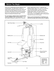
If you for selecting the versatile WEIDER¨ XP23 Training System. High Pulley Station Lat Bar Butterfly Arm Curl Pad Leg Lever Low Pulley Station Row Bar Foot Plate 4 Butterfly Arm Backrest Press Arm Seat Shroud Covering Weight Stack ASSEMBLED DIMENSIONS: Height: 77 in . Length: 61 in . Before You Begin Thank you have additional questions, please call our Customer Service Department toll-free at 1-800-999-3756, Monday through Friday...
If you for selecting the versatile WEIDER¨ XP23 Training System. High Pulley Station Lat Bar Butterfly Arm Curl Pad Leg Lever Low Pulley Station Row Bar Foot Plate 4 Butterfly Arm Backrest Press Arm Seat Shroud Covering Weight Stack ASSEMBLED DIMENSIONS: Height: 77 in . Length: 61 in . Before You Begin Thank you have additional questions, please call our Customer Service Department toll-free at 1-800-999-3756, Monday through Friday...

English Manual
Page 5
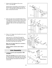
... and the upright frames that serve as a unit Arm Assembly Completes the press and butterfly arms that you operate while you are exercising. Most people find that all the way around the assembled equipment. Do not dispose of ratchet wrenches. The seats and all parts in the parts bag, check to see if it ! Cable Assembly Completes the cables and pulleys that connect the moving parts will...
... and the upright frames that serve as a unit Arm Assembly Completes the press and butterfly arms that you operate while you are exercising. Most people find that all the way around the assembled equipment. Do not dispose of ratchet wrenches. The seats and all parts in the parts bag, check to see if it ! Cable Assembly Completes the cables and pulleys that connect the moving parts will...

English Manual
Page 6
... Cap (11) into the end of the 2 Base (8). Locate and open the parts bag labeled ÒFRAME 5 51 ASSEMBLY.Ó Press a 2Ó Square Outer Cap (51) onto each end of the Rear 3 Upright (18). 11 Slide the Rear Upright (18) onto the 5/16Ó x 2 3/4Ó Carriage Bolts (14) in the Base (8). Press a 2Ó Square Inner Cap (21) into the top of...
... Cap (11) into the end of the 2 Base (8). Locate and open the parts bag labeled ÒFRAME 5 51 ASSEMBLY.Ó Press a 2Ó Square Outer Cap (51) onto each end of the Rear 3 Upright (18). 11 Slide the Rear Upright (18) onto the 5/16Ó x 2 3/4Ó Carriage Bolts (14) in the Base (8). Press a 2Ó Square Inner Cap (21) into the top of...

English Manual
Page 7
... align the indicated holes with the indicated holes. 23 Insert both Weight Guides (23) through the Top Frame (1) and the bracket (C) on the Front Upright (42). Pin Groove 26 6. Hand tighten a 5/16Ó Nylon Locknut (53) onto each Bolt. Do not tighten the Locknuts yet. 7 56 67 56 53 C 42 53 Set four Weight Bumpers (19) onto the Base (8) and 4 align...
... align the indicated holes with the indicated holes. 23 Insert both Weight Guides (23) through the Top Frame (1) and the bracket (C) on the Front Upright (42). Pin Groove 26 6. Hand tighten a 5/16Ó Nylon Locknut (53) onto each Bolt. Do not tighten the Locknuts yet. 7 56 67 56 53 C 42 53 Set four Weight Bumpers (19) onto the Base (8) and 4 align...
English Manual
Page 8
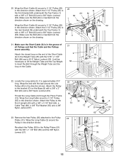
...; x 2 3/4Ó Bolts (67) through the Support Plate (27) and the indicated holes in steps 3 through 9. 9 67 Arm Assembly 10 10. Lubricate the 3/8Ó x 8Ó Bolt (59). Insert the 5/16Ó x 1 3/4Ó Bolts (58) and hand tighten two 5/16Ó Nylon Locknuts (53) onto them since this may damage the weight guides. 61 23 53 1 9. Tighten all Nylon Locknuts used in the Front Upright (42). Press a 1 1/2Ó...
...; x 2 3/4Ó Bolts (67) through the Support Plate (27) and the indicated holes in steps 3 through 9. 9 67 Arm Assembly 10 10. Lubricate the 3/8Ó x 8Ó Bolt (59). Insert the 5/16Ó x 1 3/4Ó Bolts (58) and hand tighten two 5/16Ó Nylon Locknuts (53) onto them since this may damage the weight guides. 61 23 53 1 9. Tighten all Nylon Locknuts used in the Front Upright (42). Press a 1 1/2Ó...

English Manual
Page 9
...Arm. Butterfly Arm Assembly. Lubricate both axles (H) on the seat. Press a 2Ó Square Inner Cap (21) into the lower end of the welded bracket (G) on each Press Arm (46) to confuse the Right and Left Butterfly Arm. Press a 1Ó Round Inner Cap (49) into each Arm. Attach each Press Arm (46). Make sure the upper end of each Butterfly Arm with a rubber mallet. Attach the Left Butterfly Arm...bend towards the Cover Cap (3), as shown in the same manner. To do this step. Note: Be careful not to the Press Frame (12) with two 5/16Ó x 2 3/4Ó Bolts (67) and...
...Arm. Butterfly Arm Assembly. Lubricate both axles (H) on the seat. Press a 2Ó Square Inner Cap (21) into the lower end of the welded bracket (G) on each Press Arm (46) to confuse the Right and Left Butterfly Arm. Press a 1Ó Round Inner Cap (49) into each Arm. Attach each Press Arm (46). Make sure the upper end of each Butterfly Arm with a rubber mallet. Attach the Left Butterfly Arm...bend towards the Cover Cap (3), as shown in the same manner. To do this step. Note: Be careful not to the Press Frame (12) with two 5/16Ó x 2 3/4Ó Bolts (67) and...

English Manual
Page 10
...). Attach the 3 1/2Ó Pulley to prevent the Eyebolt from the ARM ASSEMBLY parts bag will hold the Cable in the direction shown. Make sure the Long Cable Trap is positioned as shown, so it will be explained in 15 the direction shown. Tighten the Plain Nut to the Top Frame (1) with the Bolt and a 5/16Ó Nylon Jamnut (80). Locate and open the parts...
...). Attach the 3 1/2Ó Pulley to prevent the Eyebolt from the ARM ASSEMBLY parts bag will hold the Cable in the direction shown. Make sure the Long Cable Trap is positioned as shown, so it will be explained in 15 the direction shown. Tighten the Plain Nut to the Top Frame (1) with the Bolt and a 5/16Ó Nylon Jamnut (80). Locate and open the parts...

English Manual
Page 11
... 60 31 11 Move to the Pulley Plates (31) with the Nylon Locknut. Remove the 3 1/2Ó 19 Pulley (35) attached to the Left Butterfly Arm (47) with a 3/8Ó x 2Ó Bolt (62) and a 3/8Ó Nylon Locknut (63). Wrap the Short Cable (9) around a 3 1/2Ó Pulley (35) in the direction shown. Re-attach the Pulley (35) to the other side of the unit. Tighten the Locknut...
... 60 31 11 Move to the Pulley Plates (31) with the Nylon Locknut. Remove the 3 1/2Ó 19 Pulley (35) attached to the Left Butterfly Arm (47) with a 3/8Ó x 2Ó Bolt (62) and a 3/8Ó Nylon Locknut (63). Wrap the Short Cable (9) around a 3 1/2Ó Pulley (35) in the direction shown. Re-attach the Pulley (35) to the other side of the unit. Tighten the Locknut...
English Manual
Page 12
...). Attach the 3 1/2Ó Pulley (35) to insert the Bolt through the Press Frame (12). It is in the direction shown. Attach the Pulley to the Weight Tube (25) with a 3/8Ó x 3 1/2Ó Bolt (54), a Cable Trap (66), a 3/8Ó Flat Washer (55) and a 3/8Ó Nylon Jamnut (57). 22 66 54 23. Attach the closed loop on the Cable. 22. Wrap the Long Cable around a 3 1/2Ó Pulley (35...
...). Attach the 3 1/2Ó Pulley (35) to insert the Bolt through the Press Frame (12). It is in the direction shown. Attach the Pulley to the Weight Tube (25) with a 3/8Ó x 3 1/2Ó Bolt (54), a Cable Trap (66), a 3/8Ó Flat Washer (55) and a 3/8Ó Nylon Jamnut (57). 22 66 54 23. Attach the closed loop on the Cable. 22. Wrap the Long Cable around a 3 1/2Ó Pulley (35...

English Manual
Page 13
Move to the Front Upright (42) with a 3/8Ó x 3 1/4Ó Bolt (69), a Cable Trap (66), a 3/8Ó Flat Washer (55) and a 3/8Ó Nylon Locknut (63). Attach the Pulley to the other side of the unit. Pulley (6) in the direction shown. Attach the Pulley to the bracket (P) on the Seat Frame (36) with a 3/8Ó x 3 1/2Ó Bolt (54), a Cable Trap (66), a 3/8Ó Flat Washer (55) and a 3/8Ó Nylon...
Move to the Front Upright (42) with a 3/8Ó x 3 1/4Ó Bolt (69), a Cable Trap (66), a 3/8Ó Flat Washer (55) and a 3/8Ó Nylon Locknut (63). Attach the Pulley to the other side of the unit. Pulley (6) in the direction shown. Attach the Pulley to the bracket (P) on the Seat Frame (36) with a 3/8Ó x 3 1/2Ó Bolt (54), a Cable Trap (66), a 3/8Ó Flat Washer (55) and a 3/8Ó Nylon...

English Manual
Page 14
... the Carriage Bolt. Attach the other end of the Long Cable (2) onto the Eyebolt (44) with a 3/8Ó x 3 1/2Ó Bolt (54), a Cable Trap (66), a 3/8Ó Flat Washer (55) and a 3/8Ó Nylon Jamnut (57). Tighten a 1/4Ó Nylon Locknut (82) with two 1/4Ó x 2 1/2Ó Screws. 43 2 73 44 42 41 43 30. Locate and open the parts bag labeled ÒSEAT ASSEMBLY.Ó Attach the Backrest...
... the Carriage Bolt. Attach the other end of the Long Cable (2) onto the Eyebolt (44) with a 3/8Ó x 3 1/2Ó Bolt (54), a Cable Trap (66), a 3/8Ó Flat Washer (55) and a 3/8Ó Nylon Jamnut (57). Tighten a 1/4Ó Nylon Locknut (82) with two 1/4Ó x 2 1/2Ó Screws. 43 2 73 44 42 41 43 30. Locate and open the parts bag labeled ÒSEAT ASSEMBLY.Ó Attach the Backrest...

English Manual
Page 15
... 34 29 Miscellaneous Assembly 32 32. Move to the other Pad Tube into each cable a few times to the Curl Post (10) with the opening for adjusting the Weights. Before using the home gym system, pull each Pad 31 Tube (28). See TROUBLE-SHOOTING AND MAINTENANCE on page 17 of the #8 x 1/2Ó Tap Screws (7). 31. The use of the unit and attach the Right...
... 34 29 Miscellaneous Assembly 32 32. Move to the other Pad Tube into each cable a few times to the Curl Post (10) with the opening for adjusting the Weights. Before using the home gym system, pull each Pad 31 Tube (28). See TROUBLE-SHOOTING AND MAINTENANCE on page 17 of the #8 x 1/2Ó Tap Screws (7). 31. The use of the unit and attach the Right...
English Manual
Page 17
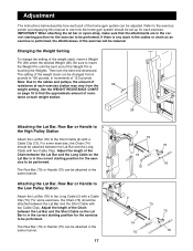
... the home gym system can be attached in the same manner. 17 9 73 75 74 76 70 2 74 70 73 75 76 Use the WEIGHT RESISTANCE CHART on page 18 to find the approximate amount of the Chain between the Lat Bar and the Short Cable so the Lat Bar is in the correct starting position for the exercise to be set up for each exercise. Adjust...
... the home gym system can be attached in the same manner. 17 9 73 75 74 76 70 2 74 70 73 75 76 Use the WEIGHT RESISTANCE CHART on page 18 to find the approximate amount of the Chain between the Lat Bar and the Short Cable so the Lat Bar is in the correct starting position for the exercise to be set up for each exercise. Adjust...
English Manual
Page 18
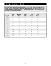
The other numbers refer to the 12.5 lbs. top weight. weight plates. Note: The actual resistance at each weight station may vary due to differences in individual weight plates, as well as friction between the cables, pulleys, and weight guides. Weight Plates Top 1 2 3 4 5 6 7 8 Press Arm (lbs.) 12 40 62 86 94 127 150 160 193 Butterfly Arm (lbs.) 46 70 97 110 141 162 180...
The other numbers refer to the 12.5 lbs. top weight. weight plates. Note: The actual resistance at each weight station may vary due to differences in individual weight plates, as well as friction between the cables, pulleys, and weight guides. Weight Plates Top 1 2 3 4 5 6 7 8 Press Arm (lbs.) 12 40 62 86 94 127 150 160 193 Butterfly Arm (lbs.) 46 70 97 110 141 162 180...

English Manual
Page 19
... instructions on moving the ÒVÓ-Pulley (6) to one of turns until the Cables feel tighter. If the Cables need to prevent the Eyebolt from the top. Do not use the home gym system. To do this manual. 1 P 63 55 6 69 36 66 19 Remove the Cable and re-install it with the Bolt, Washer, Cable Trap and Locknut. Tighten the Plain Nut to be removed by moving the Weight Pin. Trouble...
... instructions on moving the ÒVÓ-Pulley (6) to one of turns until the Cables feel tighter. If the Cables need to prevent the Eyebolt from the top. Do not use the home gym system. To do this manual. 1 P 63 55 6 69 36 66 19 Remove the Cable and re-install it with the Bolt, Washer, Cable Trap and Locknut. Tighten the Plain Nut to be removed by moving the Weight Pin. Trouble...

English Manual
Page 21
... Cap Press Frame Seat 5/16Ó x 2 3/4Ó Carriage Bolt Plastic Bushing Top Weight 1/4Ó x 1/2Ó Screw Rear Upright Weight Bumper Pulley Bracket 2Ó Square Inner Cap 5/16Ó x 2 1/2Ó Bolt Weight Guide Curl Pad Weight Tube Weight Support Plate Pad Tube Leg Lever Foam Roller Pulley Plate 5/16Ó Plain Nut 1 1/2Ó Square Inner Cap 3/4Ó Round Inner Cap 3 1/2Ó Pulley Seat Frame Seat Plate 1/4Ó x 2Ó Carriage Bolt Weight Pin Low Pulley Backrest Front Upright...
... Cap Press Frame Seat 5/16Ó x 2 3/4Ó Carriage Bolt Plastic Bushing Top Weight 1/4Ó x 1/2Ó Screw Rear Upright Weight Bumper Pulley Bracket 2Ó Square Inner Cap 5/16Ó x 2 1/2Ó Bolt Weight Guide Curl Pad Weight Tube Weight Support Plate Pad Tube Leg Lever Foam Roller Pulley Plate 5/16Ó Plain Nut 1 1/2Ó Square Inner Cap 3/4Ó Round Inner Cap 3 1/2Ó Pulley Seat Frame Seat Plate 1/4Ó x 2Ó Carriage Bolt Weight Pin Low Pulley Backrest Front Upright...

English Manual
Page 25
... (WEIDER¨ XP23 Training System). 3. The SERIAL NUMBER of the product (see the PART LIST and EXPLODED DRAWING attached at 1-800-999-3756, Monday through Friday, 6 a.m. To help us assist you, please be prepared to give the following information: 1. The KEY NUMBER and DESCRIPTION of the part(s) (see the front cover of this manual). 4. Ordering Replacement Parts To order replacement parts, simply call our Customer Service Department toll-free...
... (WEIDER¨ XP23 Training System). 3. The SERIAL NUMBER of the product (see the PART LIST and EXPLODED DRAWING attached at 1-800-999-3756, Monday through Friday, 6 a.m. To help us assist you, please be prepared to give the following information: 1. The KEY NUMBER and DESCRIPTION of the part(s) (see the front cover of this manual). 4. Ordering Replacement Parts To order replacement parts, simply call our Customer Service Department toll-free...


