
User Manual
Page 2
Remove the PART IDENTIFICATION CHART and the PART LIST/EXPLODED DRAWING before beginning assembly. 2 TABLE OF CONTENTS IMPORTANT PRECAUTIONS 3 BEFORE YOU BEGIN 4 ASSEMBLY 5 HOW TO USE THE HOME GYM SYSTEM 17 TROUBLESHOOTING AND MAINTENANCE 19 CABLE DIAGRAM 20 ORDERING REPLACEMENT PARTS 23 LIMITED WARRANTY Back Cover Note: A PART IDENTIFICATION CHART and a PART LIST/EXPLODED DRAWING are attached in the center of this manual.
Remove the PART IDENTIFICATION CHART and the PART LIST/EXPLODED DRAWING before beginning assembly. 2 TABLE OF CONTENTS IMPORTANT PRECAUTIONS 3 BEFORE YOU BEGIN 4 ASSEMBLY 5 HOW TO USE THE HOME GYM SYSTEM 17 TROUBLESHOOTING AND MAINTENANCE 19 CABLE DIAGRAM 20 ORDERING REPLACEMENT PARTS 23 LIMITED WARRANTY Back Cover Note: A PART IDENTIFICATION CHART and a PART LIST/EXPLODED DRAWING are attached in the center of this manual.
User Manual
Page 4
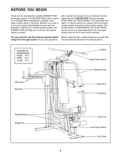
... body, build dramatic muscle size and strength, or improve your cardiovascular system, the WEIDER® 8530 will help us assist you have questions the parts that are labeled in . The WEIDER® 8530 offers a selection of weight stations designed to the home gym system (see the ...front cover of the body. If you , please note the product model number and serial number before Before reading further, please familiarize yourself with using the home gym system. Width: 60 in . ASSEMBLED...
... body, build dramatic muscle size and strength, or improve your cardiovascular system, the WEIDER® 8530 will help us assist you have questions the parts that are labeled in . The WEIDER® 8530 offers a selection of weight stations designed to the home gym system (see the ...front cover of the body. If you , please note the product model number and serial number before Before reading further, please familiarize yourself with using the home gym system. Width: 60 in . ASSEMBLED...
User Manual
Page 5
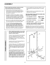
... Wait until you have been preattached for each stage is divided into five stages: 1) frame assembly, 2) press and butterfly arm assembly, 3) cable and pulley assembly, 4) seat and backrest assembly, and 5) VKR assembly. Assembly will also be on the Stabilizer. Insert four 5/16" x 2 1/2" Carriage Bolts (1) ...the Squat Arm Upright (56) onto the 5/16" x 2 1/2" Carriage Bolts (1) in the center of the Base (4). ASSEMBLY Before beginning assembly, carefully read and understand the information in the box above. Note: Some small parts may have the following information and instructions:...
... Wait until you have been preattached for each stage is divided into five stages: 1) frame assembly, 2) press and butterfly arm assembly, 3) cable and pulley assembly, 4) seat and backrest assembly, and 5) VKR assembly. Assembly will also be on the Stabilizer. Insert four 5/16" x 2 1/2" Carriage Bolts (1) ...the Squat Arm Upright (56) onto the 5/16" x 2 1/2" Carriage Bolts (1) in the center of the Base (4). ASSEMBLY Before beginning assembly, carefully read and understand the information in the box above. Note: Some small parts may have the following information and instructions:...
User Manual
Page 6
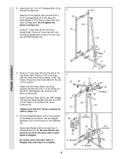
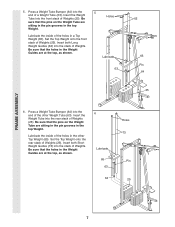
Do not tighten the Nylon Locknuts yet. 27 56 Press a 1" Inner Cap (6) into the VKR Upright (74). 42 FRAME ASSEMBLY 6 3 4 3. Press a 2" Inner Cap (27) into each set of the 5/16" Nylon Locknuts (3) used in the Base (4). Stack eight Weights (25) onto each end of the ...
Do not tighten the Nylon Locknuts yet. 27 56 Press a 1" Inner Cap (6) into the VKR Upright (74). 42 FRAME ASSEMBLY 6 3 4 3. Press a 2" Inner Cap (27) into each set of the 5/16" Nylon Locknuts (3) used in the Base (4). Stack eight Weights (25) onto each end of the ...
User Manual
Page 7
... are sitting in the pin grooves in the Weight Guides are at the top, as shown. 5 Holes Lubricate 63 62 65 Pin 64 25 6. FRAME ASSEMBLY 5. Insert the Weight Tube into the stack of Weights (25). Set the Top Weight onto the front stack of Weights (25). Be sure that the...
... are sitting in the pin grooves in the Weight Guides are at the top, as shown. 5 Holes Lubricate 63 62 65 Pin 64 25 6. FRAME ASSEMBLY 5. Insert the Weight Tube into the stack of Weights (25). Set the Top Weight onto the front stack of Weights (25). Be sure that the...
User Manual
Page 8
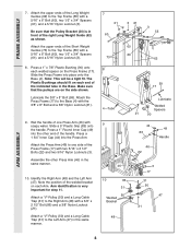
... the Press Arm. Attach the Press Arm (46) to the Top Frame (55) with two 5/16" x 2 1/2" Bolts (22) and two 5/16" Nylon Locknuts (3). FRAME ASSEMBLY 7. Press a 1 3/4" Inner Cap (44) into the other Press Arm (46) in front of the handle. Make sure that the Pulley Bracket (20) is very important... for step 11. Note: This will be a tight fit. Assemble the other end of the right Long Weight Guide (62) as shown. Arm identification is in the same manner. 10. Be sure that the pulleys...
... the Press Arm. Attach the Press Arm (46) to the Top Frame (55) with two 5/16" x 2 1/2" Bolts (22) and two 5/16" Nylon Locknuts (3). FRAME ASSEMBLY 7. Press a 1 3/4" Inner Cap (44) into the other Press Arm (46) in front of the handle. Make sure that the Pulley Bracket (20) is very important... for step 11. Note: This will be a tight fit. Assemble the other end of the right Long Weight Guide (62) as shown. Arm identification is in the same manner. 10. Be sure that the pulleys...
User Manual
Page 9
... end of the Handle. Be sure that the teeth on the Top Frame (55). Slide a 5" Plastic Grip (83) onto the Handle. Assemble another Handle (82) to identify the Right Arm. ARM ASSEMBLY 11. Press 1 3/4" Inner Caps (44) into the lower ends of the "V" Pulley (50) to the other end of the Right...
... end of the Handle. Be sure that the teeth on the Top Frame (55). Slide a 5" Plastic Grip (83) onto the Handle. Assemble another Handle (82) to identify the Right Arm. ARM ASSEMBLY 11. Press 1 3/4" Inner Caps (44) into the lower ends of the "V" Pulley (50) to the other end of the Right...
User Manual
Page 10
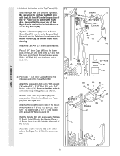
... the CABLE DIA- 13 GRAM on page 19 of the Pulley and that the Cable is in place. 86 58 31 31 86 50 CABLE ASSEMBLY Route the Medium Cable (58) around the "V"Pulley (50) on the Left Arm (47). Be sure that the Cable is inside the Long "U"-Bracket. (Note...
... the CABLE DIA- 13 GRAM on page 19 of the Pulley and that the Cable is in place. 86 58 31 31 86 50 CABLE ASSEMBLY Route the Medium Cable (58) around the "V"Pulley (50) on the Left Arm (47). Be sure that the Cable is inside the Long "U"-Bracket. (Note...
User Manual
Page 11
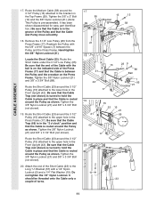
... the Cable Trap (66) is in the Press Frame (17). Tighten the 3/8" Nylon Locknut (21) and 3/8" x 3 3/4" Bolt (not shown). 20. CABLE ASSEMBLY 17. Be sure that the Cable is pre-assembled. Route the Short Cable (23) around the Pulley as shown. Attach the end of turns. 17 55 15 12 Bracket 58...
... the Cable Trap (66) is in the Press Frame (17). Tighten the 3/8" Nylon Locknut (21) and 3/8" x 3 3/4" Bolt (not shown). 20. CABLE ASSEMBLY 17. Be sure that the Cable is pre-assembled. Route the Short Cable (23) around the Pulley as shown. Attach the end of turns. 17 55 15 12 Bracket 58...
User Manual
Page 12
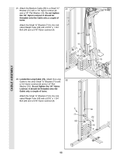
...) with a 1/4" Nylon Locknut (2) and a 1/4" Flat Washer (10). It should be threaded onto the Cable only a couple of turns. Do not tighten the 1/4" Nylon Locknut. CABLE ASSEMBLY 21. Attach the Medium Cable (58) to the other Small "U"-Bracket (71) with a 1/4" Nylon Locknut (2) and a 1/4" Flat Washer (10).
...) with a 1/4" Nylon Locknut (2) and a 1/4" Flat Washer (10). It should be threaded onto the Cable only a couple of turns. Do not tighten the 1/4" Nylon Locknut. CABLE ASSEMBLY 21. Attach the Medium Cable (58) to the other Small "U"-Bracket (71) with a 1/4" Nylon Locknut (2) and a 1/4" Flat Washer (10).
User Manual
Page 13
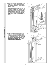
... Top Frame (55). Attach the Pulley and a Cable Trap (66) to hold the Cable in place. 66 15 15 5 21 84 92 Bracket 72 CABLE ASSEMBLY 13 Tighten the 3/8" Nylon Locknut (21) and the 3/8" x 2" Bolt (not shown). Be sure that the 3/8" Jam Nut is on the Stabilizer (5) with the 3/8" x 2 1/4" Bolt (94...
... Top Frame (55). Attach the Pulley and a Cable Trap (66) to hold the Cable in place. 66 15 15 5 21 84 92 Bracket 72 CABLE ASSEMBLY 13 Tighten the 3/8" Nylon Locknut (21) and the 3/8" x 2" Bolt (not shown). Be sure that the 3/8" Jam Nut is on the Stabilizer (5) with the 3/8" x 2 1/4" Bolt (94...
User Manual
Page 14
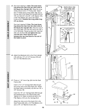
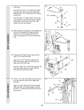
... Screw (81). 38 37 32 18 36 81 10 2 14 Attach the other side A 21 9 76 56 72 67 50 31 B 92 94 72 SEAT ASSEMBLY 26. Note: The inset drawing shows the view from other end of the 3/8" x 2 1/4" Bolt (94). Thread another 3/8" Jam Nut (92) onto the Bolt. ...Arm Upright with two 1/4" x 3/4" Screws (18). Tighten a 1/4" Nylon Locknut (2) with two 1/4" x 2 1/2" Screws (43) and two 1/4" Flat Washers (10). 42 41 43 10 27. CABLE ASSEMBLY 25. See inset drawing A. Attach the "V"-Pulley and a Long Cable Trap (31) to pivot. 25 50 72 Insets show view from the other side of...
... Screw (81). 38 37 32 18 36 81 10 2 14 Attach the other side A 21 9 76 56 72 67 50 31 B 92 94 72 SEAT ASSEMBLY 26. Note: The inset drawing shows the view from other end of the 3/8" x 2 1/4" Bolt (94). Thread another 3/8" Jam Nut (92) onto the Bolt. ...Arm Upright with two 1/4" x 3/4" Screws (18). Tighten a 1/4" Nylon Locknut (2) with two 1/4" x 2 1/2" Screws (43) and two 1/4" Flat Washers (10). 42 41 43 10 27. CABLE ASSEMBLY 25. See inset drawing A. Attach the "V"-Pulley and a Long Cable Trap (31) to pivot. 25 50 72 Insets show view from the other side of...
User Manual
Page 15
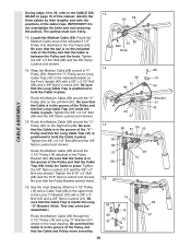
Tighten a 3/8" Nylon Locknut (21) with two 5/16" x 3" Bolts (75) and two 5/16" Nylon Locknuts (3). 79 80 3 32 32 15 VKR ASSEMBLY Slide a 6" Pad (30) onto each end of the Pad Tube. 34 36 30 28 30 34 29 31. Slide a 6" Foam Pad (30) onto each 13 1/2" ... Frame (36) with a 5/16" x 2 3/4" Carriage Bolt (14) and the Seat Knob (40). 28 33-Lubricate 36 3 29 35 32 9 21 29 42 40 36 SEAT ASSEMBLY 14 Pin 30. 28. Press a 1 1/2" Inner Cap (32) into the Leg Lever (29) from the direction shown. Insert the other 13 1/2" Pad Tube (28) into...
Tighten a 3/8" Nylon Locknut (21) with two 5/16" x 3" Bolts (75) and two 5/16" Nylon Locknuts (3). 79 80 3 32 32 15 VKR ASSEMBLY Slide a 6" Pad (30) onto each end of the Pad Tube. 34 36 30 28 30 34 29 31. Slide a 6" Foam Pad (30) onto each 13 1/2" ... Frame (36) with a 5/16" x 2 3/4" Carriage Bolt (14) and the Seat Knob (40). 28 33-Lubricate 36 3 29 35 32 9 21 29 42 40 36 SEAT ASSEMBLY 14 Pin 30. 28. Press a 1 1/2" Inner Cap (32) into the Leg Lever (29) from the direction shown. Insert the other 13 1/2" Pad Tube (28) into...
User Manual
Page 16
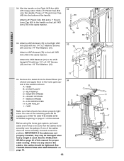
... page 17 of this manual for proper cable routing. If there is any slack in the same manner. 32 83 80 49 79 83 VKR ASSEMBLY 33. Press a 1" Round Inner Cap (49) into the bottom of the cables does not move smoothly over the pulleys. Before using the ...same manner. 32. Slide a 5" Plastic Grip (83) onto the Handle. Attach the VKR Backrest (77) to the Left VKR Arm (79) in the locations shown: B A -8530 B -HIGH PULLEY C -BUTTERFLY D-MILITARY PRESS A E -SQUAT STATION F -BENCH PRESS G-LEG DEVELOPER H-LOW PULLEY I -VKR I Make sure that the cables move smoothly, find ...
... page 17 of this manual for proper cable routing. If there is any slack in the same manner. 32 83 80 49 79 83 VKR ASSEMBLY 33. Press a 1" Round Inner Cap (49) into the bottom of the cables does not move smoothly over the pulleys. Before using the ...same manner. 32. Slide a 5" Plastic Grip (83) onto the Handle. Attach the VKR Backrest (77) to the Left VKR Arm (79) in the locations shown: B A -8530 B -HIGH PULLEY C -BUTTERFLY D-MILITARY PRESS A E -SQUAT STATION F -BENCH PRESS G-LEG DEVELOPER H-LOW PULLEY I -VKR I Make sure that the cables move smoothly, find ...
User Manual
Page 20
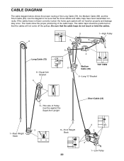
... traps should be against the Squat Arm Upright Short Cable (23) 3 1-Rear Weight Stack 4 8-Front Weight 3 Stack 2 1-Low Pulley 20 If the cables have been assembled correctly. The insets show the proper positioning of the Long Cable (72), the Medium Cable (58), and the Short Cable (23). CABLE DIAGRAM The cable...
... traps should be against the Squat Arm Upright Short Cable (23) 3 1-Rear Weight Stack 4 8-Front Weight 3 Stack 2 1-Low Pulley 20 If the cables have been assembled correctly. The insets show the proper positioning of the Long Cable (72), the Medium Cable (58), and the Short Cable (23). CABLE DIAGRAM The cable...
User Manual
Page 25
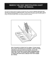
...it has been pre-assembled. Note: Assembly is divided into five stages: 1) frame assembly, 2) press and butterfly arm assembly, 3) cable and pulley assembly, 4) seat and backrest assembly, and 5) VKR assembly. WAIT UNTIL YOU BEGIN EACH ASSEMBLY STAGE TO OPEN THE PARTS BAG LABELED FOR THAT ASSEMBLY STAGE. If you ...in parenthesis below each stage is packaged separately. Important: Some parts may have been pre-assembled for each part refers to help you cannot find a part in assembly. REMOVE THIS PART IDENTIFICATION CHART FROM THE MANUAL This chart is provided to the key number...
...it has been pre-assembled. Note: Assembly is divided into five stages: 1) frame assembly, 2) press and butterfly arm assembly, 3) cable and pulley assembly, 4) seat and backrest assembly, and 5) VKR assembly. WAIT UNTIL YOU BEGIN EACH ASSEMBLY STAGE TO OPEN THE PARTS BAG LABELED FOR THAT ASSEMBLY STAGE. If you ...in parenthesis below each stage is packaged separately. Important: Some parts may have been pre-assembled for each part refers to help you cannot find a part in assembly. REMOVE THIS PART IDENTIFICATION CHART FROM THE MANUAL This chart is provided to the key number...


