
User Manual
Page 2
... be received by ICON. All returns must be pre-authorized by ICON at one of its scope and duration to the terms set forth above limitation may also have other consequential damages of whatsoever nature. The warranty extended hereunder is authorized by an ICON authorized ... not apply to you. TABLE OF CONTENTS LIMITED WARRANTY IMPORTANT PRECAUTIONS BEFORE YOU BEGIN ASSEMBLY HOW TO USE THE HOME GYM SYSTEM TROUBLESHOOTING AND MAINTENANCE CABLE DIAGRAM ORDERING REPLACEMENT PARTS 2 3 4 5 15 18 19 Back Cover Note: A PART IDENTIFICATION CHART and a PART LIST/EXPLODED DRAWING are...
... be received by ICON. All returns must be pre-authorized by ICON at one of its scope and duration to the terms set forth above limitation may also have other consequential damages of whatsoever nature. The warranty extended hereunder is authorized by an ICON authorized ... not apply to you. TABLE OF CONTENTS LIMITED WARRANTY IMPORTANT PRECAUTIONS BEFORE YOU BEGIN ASSEMBLY HOW TO USE THE HOME GYM SYSTEM TROUBLESHOOTING AND MAINTENANCE CABLE DIAGRAM ORDERING REPLACEMENT PARTS 2 3 4 5 15 18 19 Back Cover Note: A PART IDENTIFICATION CHART and a PART LIST/EXPLODED DRAWING are...
User Manual
Page 5
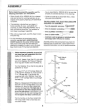
... the Rear Upright (56) with soapy water. Press a 2" Square Inner Cap (27) into four stages: 1) frame assembly, 2) press and butterfly arm assembly, 3) cable and pulley assembly, and 4) seat and backrest assembly. Insert a 5/16" x 2 1/2" Carriage Bolt (1) up through the Base (4). The high side of the bracket ... As you assemble them, unless instructed to open -end or closed-end wrenches, or a set of open that all parts are oriented as shown in the drawings. • Tighten all parts of the WEIDER 8515 in a cleared area and remove the packing materials; Slide the Rear Upright (56) onto ...
... the Rear Upright (56) with soapy water. Press a 2" Square Inner Cap (27) into four stages: 1) frame assembly, 2) press and butterfly arm assembly, 3) cable and pulley assembly, and 4) seat and backrest assembly. Insert a 5/16" x 2 1/2" Carriage Bolt (1) up through the Base (4). The high side of the bracket ... As you assemble them, unless instructed to open -end or closed-end wrenches, or a set of open that all parts are oriented as shown in the drawings. • Tighten all parts of the WEIDER 8515 in a cleared area and remove the packing materials; Slide the Rear Upright (56) onto ...
User Manual
Page 15
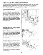
... position for each exercise. For some exercises, the Chain (52) should be attached between the Lat Bar and the Long Cable with two Cable Clips. CHANGING THE WEIGHT SETTING To change the weight setting of the exercise will be reduced. The Nylon Strap (39) (not shown) can be changed from the weight...Weight Pin until the bent end of the Weight Pin is in the correct starting position for the exercise to the Long Cable (23) with a Cable Clip (53). The weight setting of the weight stack can be attached in the same manner. Adjust the length of the Chain between the Lat Bar...
... position for each exercise. For some exercises, the Chain (52) should be attached between the Lat Bar and the Long Cable with two Cable Clips. CHANGING THE WEIGHT SETTING To change the weight setting of the exercise will be reduced. The Nylon Strap (39) (not shown) can be changed from the weight...Weight Pin until the bent end of the Weight Pin is in the correct starting position for the exercise to the Long Cable (23) with a Cable Clip (53). The weight setting of the weight stack can be attached in the same manner. Adjust the length of the Chain between the Lat Bar...
User Manual
Page 16
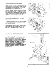
... Seat Knob (40) and the 5/16" x 2 3/4" Carriage Bolt (14) from the Rear Upright (56), the greater the resistance will be attached to the Short Cable (58) with a Cable Clip (53). Attach the Seat Frame to the Eyebolt (35) with the 5/16" x 2 3/4" Carriage Bolt (14) and the Seat Knob (40). CHANGING THE ... from the Seat Frame (36). First, be removed. Make sure that the chain is not attached to the leg lever. ATTACHING AND REMOVING THE SEAT Set the bracket on the Seat Frame (36) onto the indicated pins on both Pedals. For some exercises, the Seat (13) must be . Lift the ...
... Seat Knob (40) and the 5/16" x 2 3/4" Carriage Bolt (14) from the Rear Upright (56), the greater the resistance will be attached to the Short Cable (58) with a Cable Clip (53). Attach the Seat Frame to the Eyebolt (35) with the 5/16" x 2 3/4" Carriage Bolt (14) and the Seat Knob (40). CHANGING THE ... from the Seat Frame (36). First, be removed. Make sure that the chain is not attached to the leg lever. ATTACHING AND REMOVING THE SEAT Set the bracket on the Seat Frame (36) onto the indicated pins on both Pedals. For some exercises, the Seat (13) must be . Lift the ...


