

Operation Manual
Page 1
..., both within and after the warranty period, should only be found on the latest product information available at the time of authorized service dealers near you. Operator's Manual Electric Start Capable 4-Cycle Trimmer TB6044 XP TABLE OF CONTENTS Service 1 Safety 2 Know Your Unit 5 Specifications 5 Assembly 6 Oil and Fuel 8 Starting and Stopping 10 Operation 12 Maintenance 13 Cleaning and Storage 17 Troubleshooting 18 Warranty 20 SAVE THESE INSTRUCTIONS SERVICE DO NOT RETURN THIS UNIT TO...
..., both within and after the warranty period, should only be found on the latest product information available at the time of authorized service dealers near you. Operator's Manual Electric Start Capable 4-Cycle Trimmer TB6044 XP TABLE OF CONTENTS Service 1 Safety 2 Know Your Unit 5 Specifications 5 Assembly 6 Oil and Fuel 8 Starting and Stopping 10 Operation 12 Maintenance 13 Cleaning and Storage 17 Troubleshooting 18 Warranty 20 SAVE THESE INSTRUCTIONS SERVICE DO NOT RETURN THIS UNIT TO...
Operation Manual
Page 2
... possible dangers. SPARK ARRESTOR NOTE NOTE: For users on forest brush and/or grass-covered areas be thrown or become dangerous projectiles. Wash hands after handling. Never remove the fuel tank cap or add fuel when the engine is highly flammable and its constituents and certain finished components contain or emit chemicals known to the State of injury to install the Accessory Part #753-08052 Muffler Assembly. Move...
... possible dangers. SPARK ARRESTOR NOTE NOTE: For users on forest brush and/or grass-covered areas be thrown or become dangerous projectiles. Wash hands after handling. Never remove the fuel tank cap or add fuel when the engine is highly flammable and its constituents and certain finished components contain or emit chemicals known to the State of injury to install the Accessory Part #753-08052 Muffler Assembly. Move...

Operation Manual
Page 3
... damaged parts. • Turn the engine to another. • If you loan this manual, should be in place while operating the unit. Stop the unit. 2. SAVE THESE INSTRUCTIONS 3 Secure hair above shoulder level. • The cutting head shield must be performed by a authorized service dealer. • Before inspecting, servicing, cleaning, storing, transporting or replacing any parts on both trimming lines extended and the proper line installed. Always...
... damaged parts. • Turn the engine to another. • If you loan this manual, should be in place while operating the unit. Stop the unit. 2. SAVE THESE INSTRUCTIONS 3 Secure hair above shoulder level. • The cutting head shield must be performed by a authorized service dealer. • Before inspecting, servicing, cleaning, storing, transporting or replacing any parts on both trimming lines extended and the proper line installed. Always...
Operation Manual
Page 4
..., at high speed, causing injury. Wear eye protection meeting current ANSI Z87.1 standards and ear protection when operating this unit. Use a full face shield when needed. • UNLEADED FUEL Always use clean, fresh unleaded fuel. • OIL Refer to do not touch the line cutting blade. 4 When turned off they remain hot for complete safety, assembly, operating and maintenance and repair information. Failure to operator's manual for the proper type of oil...
..., at high speed, causing injury. Wear eye protection meeting current ANSI Z87.1 standards and ear protection when operating this unit. Use a full face shield when needed. • UNLEADED FUEL Always use clean, fresh unleaded fuel. • OIL Refer to do not touch the line cutting blade. 4 When turned off they remain hot for complete safety, assembly, operating and maintenance and repair information. Failure to operator's manual for the proper type of oil...

Operation Manual
Page 5
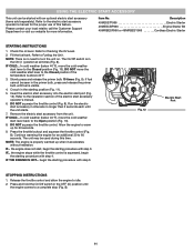
... Muffler Shaft Grip Spark Plug Throttle Lockout ASSEMBLY TOOLS REQUIRED: • #2 Phillips screwdriver • 3/8" Socket Handle On/Off Switch Shaft Housing Air Filter Cover Throttle Control Starter Rope Grip Primer Bulb Fuel Cap Cold Weather Start Lever Cutting Head Coupler Cutting Head Shield Oil Fill Plug Line Cutting Blade SPECIFICATIONS* Engine Type Air-Cooled, 4-Cycle Displacement 32 cc (1.95 cu. in.) Spark Plug Gap 0.025 in. (0.635 mm) Spark Plug Champion® RDZ4H or equivalent plug Lubrication SAE 30 Oil Crankcase Oil Capacity 2.03 oz. (60 ml) Fuel Tank Capacity...
... Muffler Shaft Grip Spark Plug Throttle Lockout ASSEMBLY TOOLS REQUIRED: • #2 Phillips screwdriver • 3/8" Socket Handle On/Off Switch Shaft Housing Air Filter Cover Throttle Control Starter Rope Grip Primer Bulb Fuel Cap Cold Weather Start Lever Cutting Head Coupler Cutting Head Shield Oil Fill Plug Line Cutting Blade SPECIFICATIONS* Engine Type Air-Cooled, 4-Cycle Displacement 32 cc (1.95 cu. in.) Spark Plug Gap 0.025 in. (0.635 mm) Spark Plug Champion® RDZ4H or equivalent plug Lubrication SAE 30 Oil Crankcase Oil Capacity 2.03 oz. (60 ml) Fuel Tank Capacity...
Operation Manual
Page 6
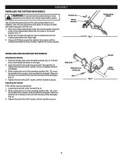
... instructions if the cutting head shield is firmly in the operating position (Fig. 13), move the handle to the right. 2. Using a #2 Phillips screwdriver, tighten the screws until the handle is secure. Place it through the mount bracket and into the bolt hole and push it a minimum of 6 inches (15.24 cm) from the end of the shaft grip (Fig. 2). 3. Screws (4) Mount Bracket Fig. 1 INSTALLING...
... instructions if the cutting head shield is firmly in the operating position (Fig. 13), move the handle to the right. 2. Using a #2 Phillips screwdriver, tighten the screws until the handle is secure. Place it through the mount bracket and into the bolt hole and push it a minimum of 6 inches (15.24 cm) from the end of the shaft grip (Fig. 2). 3. Screws (4) Mount Bracket Fig. 1 INSTALLING...
Operation Manual
Page 7
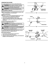
... use of the coupler (Fig. 5). Removing the Attachment 1. Turn the knob clockwise to the unit. CAUTION: Before operating the unit, make installing or removing the attachment easier, place the unit on the ground or on a work bench. CAUTION: The release button should be snapped into the primary hole (Fig. 5). 3. WARNING: Before using any attachment, read and understand the manual that came with a string trimmer attachment, lock...
... use of the coupler (Fig. 5). Removing the Attachment 1. Turn the knob clockwise to the unit. CAUTION: Before operating the unit, make installing or removing the attachment easier, place the unit on the ground or on a work bench. CAUTION: The release button should be snapped into the primary hole (Fig. 5). 3. WARNING: Before using any attachment, read and understand the manual that came with a string trimmer attachment, lock...
Operation Manual
Page 8
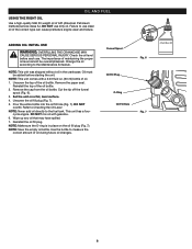
... Maintenance Schedule. NOTE: Make sure the O-ring is in the crankcase. NOTE: This unit comes with gasoline. 6. Failure to use dirty oil. Change the oil according to Checking the Oil Level. NOTE: This unit was shipped without oil in place on a flat, level surface. 4. cycle engine. Use the bottle to the fuel tank. OIL AND FUEL USING THE RIGHT OIL Use a high-quality SAE 30 weight oil of the oil bottle. 2. DO NOT use clean oil...
... Maintenance Schedule. NOTE: Make sure the O-ring is in the crankcase. NOTE: This unit comes with gasoline. 6. Failure to use dirty oil. Change the oil according to Checking the Oil Level. NOTE: This unit was shipped without oil in place on a flat, level surface. 4. cycle engine. Use the bottle to the fuel tank. OIL AND FUEL USING THE RIGHT OIL Use a high-quality SAE 30 weight oil of the oil bottle. 2. DO NOT use clean oil...
Operation Manual
Page 9
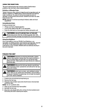
...: Gasoline is the most common cause of performance problems. Use only fresh, clean unleaded gasoline. WARNING: Remove the fuel cap slowly to the unit's fuel tank. NEVER add fuel additives directly to avoid injury from the fuel container and the fueling site before starting the engine. 9 WARNING: Add fuel in place. Avoid creating a source of old fuel according to cool before storing the unit WARNING...
...: Gasoline is the most common cause of performance problems. Use only fresh, clean unleaded gasoline. WARNING: Remove the fuel cap slowly to the unit's fuel tank. NEVER add fuel additives directly to avoid injury from the fuel container and the fueling site before starting the engine. 9 WARNING: Add fuel in place. Avoid creating a source of old fuel according to cool before storing the unit WARNING...

Operation Manual
Page 10
... start lever to turn the unit on. the engine stops while the throttle control is above 40°F. 3. Fig. 10 Starter Rope Grip Starting Position Fig. 11 10 IF COLD... NOTE: The engine is no need to the Closed position (Fig. 10). STARTING AND STOPPING WARNING: Operate this time. IF... Press and hold the On/Off switch in a confined area. Refer to idle. 2. Slowly press and release the primer bulb...
... start lever to turn the unit on. the engine stops while the throttle control is above 40°F. 3. Fig. 10 Starter Rope Grip Starting Position Fig. 11 10 IF COLD... NOTE: The engine is no need to the Closed position (Fig. 10). STARTING AND STOPPING WARNING: Operate this time. IF... Press and hold the On/Off switch in a confined area. Refer to idle. 2. Slowly press and release the primer bulb...
Operation Manual
Page 11
... (below 40°F), move the cold weather start , begin the starting procedure with step 4. Press and hold the On/Off switch in the OFF (O) position until fuel is in the starting procedure with an optional electric start accessory in the primer bulb, press and release the primer bulb until the engine comes to the Operation section of this time. Check the oil level. DO NOT squeeze the throttle control (Fig. 8).
... (below 40°F), move the cold weather start , begin the starting procedure with step 4. Press and hold the On/Off switch in the OFF (O) position until fuel is in the starting procedure with an optional electric start accessory in the primer bulb, press and release the primer bulb until the engine comes to the Operation section of this time. Check the oil level. DO NOT squeeze the throttle control (Fig. 8).
Operation Manual
Page 12
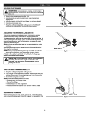
... or hard soil. CAUTION: Do not remove or alter the line cutting blade assembly. Fig. 15 12 This may stall the engine. Keep the right arm slightly bent. • Hold the handle with a Bump Head. Each time the bump knob is tapped, about 1.5 inches (38 mm) of injury when operating this unit. • Stand in tall grass may lead to serious personal injury...
... or hard soil. CAUTION: Do not remove or alter the line cutting blade assembly. Fig. 15 12 This may stall the engine. Keep the right arm slightly bent. • Hold the handle with a Bump Head. Each time the bump knob is tapped, about 1.5 inches (38 mm) of injury when operating this unit. • Stand in tall grass may lead to serious personal injury...
Operation Manual
Page 13
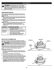
... arrows (Fig. 16). 4. Installing New Trimming Line 1. Cut one 20 foot (6 m) length of terms and coverage for the emissions control devices, such as the spark arrestor, muffler, carburetor, etc. Turn the bump knob clockwise to Maintaining the Spark Plug. These procedures should also be performed by an authorized service dealer. • Check the spark plug condition and gap. NOTE: Some maintenance procedures may cause the engine to overheat or fail...
... arrows (Fig. 16). 4. Installing New Trimming Line 1. Cut one 20 foot (6 m) length of terms and coverage for the emissions control devices, such as the spark arrestor, muffler, carburetor, etc. Turn the bump knob clockwise to Maintaining the Spark Plug. These procedures should also be performed by an authorized service dealer. • Check the spark plug condition and gap. NOTE: Some maintenance procedures may cause the engine to overheat or fail...
Operation Manual
Page 14
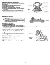
.... 2. Check the oil level before each use a flashlight if necessary. Stop the engine and allow it to clean the inner reel, outer spool and spool cover (Fig. 18). 5. The oil level should hang over the edge so that may cause the oil to overfill. 3. Clean the area around the oil fill plug (Fig. 7) to the oil fill hole until the tabs securely snap into the oil level window; Set...
.... 2. Check the oil level before each use a flashlight if necessary. Stop the engine and allow it to clean the inner reel, outer spool and spool cover (Fig. 18). 5. The oil level should hang over the edge so that may cause the oil to overfill. 3. Clean the area around the oil fill plug (Fig. 7) to the oil fill hole until the tabs securely snap into the oil level window; Set...

Operation Manual
Page 16
... observe all safety instructions to cool. Clean around the spark plug. Grit in the cylinder head. Use a feeler gauge to a qualified service dealer: • the engine will not idle, adjust the idle speed screw as needed ) to reduce the idle speed (Fig. 24). Release the throttle control and let the engine idle. Tighten the spark plug with a 5/8-inch socket, turning counterclockwise. If, after checking the fuel and cleaning the air filter, the engine still will not idle • the engine hesitates or stalls...
... observe all safety instructions to cool. Clean around the spark plug. Grit in the cylinder head. Use a feeler gauge to a qualified service dealer: • the engine will not idle, adjust the idle speed screw as needed ) to reduce the idle speed (Fig. 24). Release the throttle control and let the engine idle. Tighten the spark plug with a 5/8-inch socket, turning counterclockwise. If, after checking the fuel and cleaning the air filter, the engine still will not idle • the engine hesitates or stalls...

Operation Manual
Page 17
... the fuel cap. 2. Preparing the Unit for more than 30 days. Dispose of the unit. Remove the spark plug and put 5 drops of any high quality motor oil into an approved container. Pull the starter rope slowly to Changing the Oil. Repair or replace damaged parts and tighten loose screws, nuts or bolts. Change the oil. CLEANING AND STORAGE CLEANING WARNING: To avoid serious personal injury, always stop the engine and allow it to run...
... the fuel cap. 2. Preparing the Unit for more than 30 days. Dispose of the unit. Remove the spark plug and put 5 drops of any high quality motor oil into an approved container. Pull the starter rope slowly to Changing the Oil. Repair or replace damaged parts and tighten loose screws, nuts or bolts. Change the oil. CLEANING AND STORAGE CLEANING WARNING: To avoid serious personal injury, always stop the engine and allow it to run...

Operation Manual
Page 18
... primer bulb 10 times or until fuel is visible Drain the fuel tank and add fresh fuel Replace the spark plug Move the cold weather start lever to the open position THE ENGINE WILL NOT IDLE The air filter is dirty The fuel is old (over 30 days) The idle speed is incorrect Clean or replace the air filter Drain the fuel tank and add fresh fuel Adjust the idle speed THE ENGINE WILL NOT ACCELERATE The fuel is old (over 30 days) The cutting head...
... primer bulb 10 times or until fuel is visible Drain the fuel tank and add fresh fuel Replace the spark plug Move the cold weather start lever to the open position THE ENGINE WILL NOT IDLE The air filter is dirty The fuel is old (over 30 days) The idle speed is incorrect Clean or replace the air filter Drain the fuel tank and add fresh fuel Adjust the idle speed THE ENGINE WILL NOT ACCELERATE The fuel is old (over 30 days) The cutting head...
Operation Manual
Page 20
... States, its possessions and territories. Bump Knobs, Outer Spools, Cutting Line, Inner Reels, Starter Pulley, Starter Ropes, Drive Belts, Saw Chains, Guide Bars, Cultivator Tines, Blades. Wear items - MANUFACTURER'S LIMITED WARRANTY FOR: The limited warranty set forth below is given by Troy-Bilt LLC (Troy-Bilt) with respect to any product shall bind Troy-Bilt. This limited warranty does not provide coverage in Canada. Troy-Bilt reserves the right to change or improve the design of charge, any...
... States, its possessions and territories. Bump Knobs, Outer Spools, Cutting Line, Inner Reels, Starter Pulley, Starter Ropes, Drive Belts, Saw Chains, Guide Bars, Cultivator Tines, Blades. Wear items - MANUFACTURER'S LIMITED WARRANTY FOR: The limited warranty set forth below is given by Troy-Bilt LLC (Troy-Bilt) with respect to any product shall bind Troy-Bilt. This limited warranty does not provide coverage in Canada. Troy-Bilt reserves the right to change or improve the design of charge, any...
Parts Diagram
Page 1
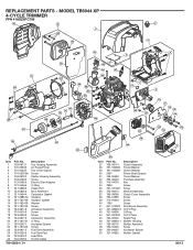
...-04595 710-04604 1755 941-012023 731-08920-9 721-04509 941-031509 794-00043 731-08903-1 753-08115 753-05246 750-06057 721-04633 Description Clutch Assembly Thrust Washer Clutch Washer Power Shaft Spacer Thrust Washer Flywheel Assembly Key Screw Screw Module Assembly Clutch Cover Assembly Screw Screw Screw Shortblock Assembly Oil Fill Plug O-Ring Oil Fill Tube Spark Plug Muffler Housing Muffler Assembly Screw Aircleaner Spacer Muffler Gasket 08/13 REPLACEMENT PARTS -
...-04595 710-04604 1755 941-012023 731-08920-9 721-04509 941-031509 794-00043 731-08903-1 753-08115 753-05246 750-06057 721-04633 Description Clutch Assembly Thrust Washer Clutch Washer Power Shaft Spacer Thrust Washer Flywheel Assembly Key Screw Screw Module Assembly Clutch Cover Assembly Screw Screw Screw Shortblock Assembly Oil Fill Plug O-Ring Oil Fill Tube Spark Plug Muffler Housing Muffler Assembly Screw Aircleaner Spacer Muffler Gasket 08/13 REPLACEMENT PARTS -
Parts Diagram
Page 2
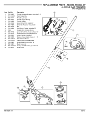
REPLACEMENT PARTS - Description 1 753-06887 Throttle Housing Assembly (includes 2 - 5) 2 791-182405 Switch Assembly 3 753-05171 Throttle Lock-out 4 753-05007 Throttle Trigger Spring 5 753-06888 Throttle Trigger 6 753-06682 Upper Drive Shaft Assembly 7 753-06889 D-Handle Assembly (includes 8) 8 753-06040 Bolt 9 753-06886 Split Boom Coupler (includes 10) 10 7682 Coupler Anti-Rotation Screw 11 753-08162 Lower Drive Shaft Housing Assembly 12 753-06125 Shield Mounting Screws and Nuts 4 13 753-05267 Lower Flexible Drive Shaft 14 753-05569...
REPLACEMENT PARTS - Description 1 753-06887 Throttle Housing Assembly (includes 2 - 5) 2 791-182405 Switch Assembly 3 753-05171 Throttle Lock-out 4 753-05007 Throttle Trigger Spring 5 753-06888 Throttle Trigger 6 753-06682 Upper Drive Shaft Assembly 7 753-06889 D-Handle Assembly (includes 8) 8 753-06040 Bolt 9 753-06886 Split Boom Coupler (includes 10) 10 7682 Coupler Anti-Rotation Screw 11 753-08162 Lower Drive Shaft Housing Assembly 12 753-06125 Shield Mounting Screws and Nuts 4 13 753-05267 Lower Flexible Drive Shaft 14 753-05569...


