Operation Manual
Page 1
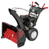
Storm 2410, 2620, 2840 & 3090XP WARNING READ AND FOLLOW ALL SAFETY RULES AND INSTRUCTIONS IN THIS MANUAL BEFORE ATTEMPTING TO OPERATE THIS MACHINE. Printed In USA TROY-BILT LLC, P.O. BOX 361131 CLEVELAND, OHIO 44136-0019 Form No. 769-06897 (May 17, 2011) FAILURE TO COMPLY WITH THESE INSTRUCTIONS MAY RESULT IN PERSONAL INJURY. Safe Operation Practices • Set-Up • Operation • Maintenance • Service • Troubleshooting • Warranty Operator's Manual Two-Stage Snow Thrower -
Storm 2410, 2620, 2840 & 3090XP WARNING READ AND FOLLOW ALL SAFETY RULES AND INSTRUCTIONS IN THIS MANUAL BEFORE ATTEMPTING TO OPERATE THIS MACHINE. Printed In USA TROY-BILT LLC, P.O. BOX 361131 CLEVELAND, OHIO 44136-0019 Form No. 769-06897 (May 17, 2011) FAILURE TO COMPLY WITH THESE INSTRUCTIONS MAY RESULT IN PERSONAL INJURY. Safe Operation Practices • Set-Up • Operation • Maintenance • Service • Troubleshooting • Warranty Operator's Manual Two-Stage Snow Thrower -
Operation Manual
Page 2
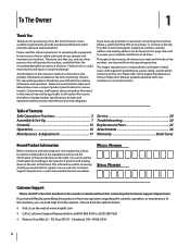
... frame. Model Number Serial Number Customer Support Please do so could result in this entire manual prior to provide excellent performance when properly operated and maintained. Please read this manual may cover a range of Contents Safe Operation Practices 3 Assembly & Set-Up 7 Controls 13 Operation 16 Maintenance & Adjustment 17 Service 20 Troubleshooting 24 Replacement Parts 25 Attachments 26 Warranty Back Cover Record Product Information Before setting up , operate and maintain your new equipment, please locate the model plate on...
... frame. Model Number Serial Number Customer Support Please do so could result in this entire manual prior to provide excellent performance when properly operated and maintained. Please read this manual may cover a range of Contents Safe Operation Practices 3 Assembly & Set-Up 7 Controls 13 Operation 16 Maintenance & Adjustment 17 Service 20 Troubleshooting 24 Replacement Parts 25 Attachments 26 Warranty Back Cover Record Product Information Before setting up , operate and maintain your new equipment, please locate the model plate on...
Operation Manual
Page 3
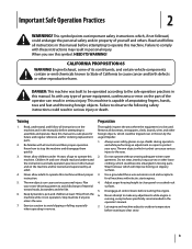
..., especially when operating in moving parts. Remove all control levers before attempting to the eyes. 2. Read, understand, and follow all controls and their proper operation. Thrown objects which , if not followed, could result in operation. Adjust auger housing height to the safe operation practices in personal injury. California Proposition 65 WARNING! DANGER: This machine was built to be used. Be familiar with electric start engines. 4. Plan your...
..., especially when operating in moving parts. Remove all control levers before attempting to the eyes. 2. Read, understand, and follow all controls and their proper operation. Thrown objects which , if not followed, could result in operation. Adjust auger housing height to the safe operation practices in personal injury. California Proposition 65 WARNING! DANGER: This machine was built to be used. Be familiar with electric start engines. 4. Plan your...
Operation Manual
Page 4
... of starter cord (kickback) will pull hand and arm toward engine faster than you l. Contact Customer Support for hidden hazards or traffic. Engine exhaust contains carbon monoxide, an odorless and deadly gas. 6. Wait 5 minutes before refueling. storing. 16. If possible, remove gas-powered equipment from your snow-throwing pattern to cool at least two minutes before starting and operating. Do not use the clean-out tool...
... of starter cord (kickback) will pull hand and arm toward engine faster than you l. Contact Customer Support for hidden hazards or traffic. Engine exhaust contains carbon monoxide, an odorless and deadly gas. 6. Wait 5 minutes before refueling. storing. 16. If possible, remove gas-powered equipment from your snow-throwing pattern to cool at least two minutes before starting and operating. Do not use the clean-out tool...
Operation Manual
Page 5
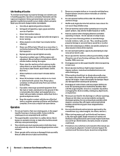
... necessary. Never store the machine or fuel container inside the discharge chute is equipped with the governor setting can result in safe working order by law (Section 4442 of this operator's manual for the muffler is equipped with spark plug removed. 14. Check fuel line, tank, cap, and fittings frequently for gas, oil, etc. Do not crank engine with a spark arrestor meeting applicable local or state laws (if any...
... necessary. Never store the machine or fuel container inside the discharge chute is equipped with the governor setting can result in safe working order by law (Section 4442 of this operator's manual for the muffler is equipped with spark plug removed. 14. Check fuel line, tank, cap, and fittings frequently for gas, oil, etc. Do not crank engine with a spark arrestor meeting applicable local or state laws (if any...
Operation Manual
Page 7
... Forward-6 position. 2. Assembly & Set-Up 3 Contents of the handle. Observe the lower rear area of the snow thrower to be sure both the left and right sides of Carton • One Snow Thrower • One Snow Thrower Operator's Manual • One Engine Manual • Two Replacement Auger Shear Pins • One Chute Assembly (Model 2410) • One Product Registration Card • One Chute Control Rod (Models 2620, 2840 and 3090XP) Assembly Handle 1. Place the shift lever in...
... Forward-6 position. 2. Assembly & Set-Up 3 Contents of the handle. Observe the lower rear area of the snow thrower to be sure both the left and right sides of Carton • One Snow Thrower • One Snow Thrower Operator's Manual • One Engine Manual • Two Replacement Auger Shear Pins • One Chute Assembly (Model 2410) • One Product Registration Card • One Chute Control Rod (Models 2620, 2840 and 3090XP) Assembly Handle 1. Place the shift lever in...
Operation Manual
Page 8
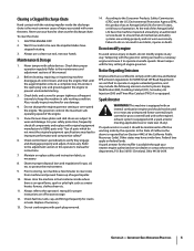
... apply swift, firm pressure to the back of the chute directional control. If necessary, the lower bracket can be adjusted. Chute Control Head Chute Support Bracket Chute Chute Base Figure 3-4 Figure 3-6 Chute Directional Control (Model 2410) 2. Remove clevis pin and bow-tie cotter pin from the end of each. See Fig. 3-4. Remove cotter pin, wing nut and hex screw from chute control head. Push rod as possible, keeping the 1. Remove the plastic cap (if present), flat...
... apply swift, firm pressure to the back of the chute directional control. If necessary, the lower bracket can be adjusted. Chute Control Head Chute Support Bracket Chute Chute Base Figure 3-4 Figure 3-6 Chute Directional Control (Model 2410) 2. Remove clevis pin and bow-tie cotter pin from the end of each. See Fig. 3-4. Remove cotter pin, wing nut and hex screw from chute control head. Push rod as possible, keeping the 1. Remove the plastic cap (if present), flat...
Operation Manual
Page 10
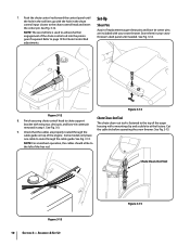
.... Assembly & Set-Up Figure 3-15 NOTE: For smoothest operation, the cables should all be to route through the Chute Clean-Out Tool The chute clean-out tool is used to the chute control head and insert the cotter pin. Finish securing chute control head to page 19 for Chute Control Rod adjustments. Refer to chute support bracket with a mounting clip and a cable tie at the factory. Figure 3-14 Figure 3-12 8. Cut the cable tie before operating the snow thrower...
.... Assembly & Set-Up Figure 3-15 NOTE: For smoothest operation, the cables should all be to route through the Chute Clean-Out Tool The chute clean-out tool is used to the chute control head and insert the cotter pin. Finish securing chute control head to page 19 for Chute Control Rod adjustments. Refer to chute support bracket with a mounting clip and a cable tie at the factory. Figure 3-14 Figure 3-12 8. Cut the cable tie before operating the snow thrower...
Operation Manual
Page 11
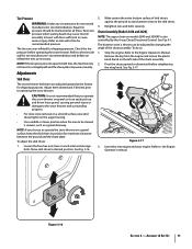
... snow thrower. Assembly & Set-Up 11 NOTE: If the tire pressure is not recommended that you choose to operate the snow thrower on the auger housing. • Use a middle or lower position when the area to cause serious injury. NOTE: If you operate this snow thrower on gravel as it can be maintained at the factory for shipping purposes. To adjust the skid shoes: 1. Retighten nuts and bolts...
... snow thrower. Assembly & Set-Up 11 NOTE: If the tire pressure is not recommended that you choose to operate the snow thrower on the auger housing. • Use a middle or lower position when the area to cause serious injury. NOTE: If you operate this snow thrower on gravel as it can be maintained at the factory for shipping purposes. To adjust the skid shoes: 1. Retighten nuts and bolts...

Operation Manual
Page 12
... to verify your snow thrower, carefully read and follow all instructions below. Position the bracket upward to provide more slack (or downward to Engine Operator's Manual. 3. Check the adjustment of motion. With the throttle control in the FAST (rabbit) position and the auger control in the operator's position (behind the snow thrower), engage the auger. 4. It should have very little slack. Repeat this several times. 5. Refer to increase cable tension). 9. Auger Control Warning!
... to verify your snow thrower, carefully read and follow all instructions below. Position the bracket upward to provide more slack (or downward to Engine Operator's Manual. 3. Check the adjustment of motion. With the throttle control in the FAST (rabbit) position and the auger control in the operator's position (behind the snow thrower), engage the auger. 4. It should have very little slack. Repeat this several times. 5. Refer to increase cable tension). 9. Auger Control Warning!
Operation Manual
Page 13
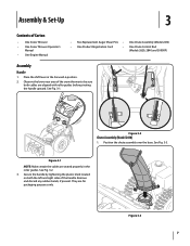
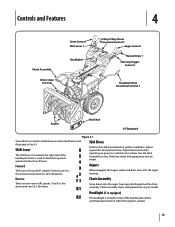
... used to determine ground speed and direction of the handle panel and is automatically turned on when the engine is the faster. Chute Assembly Snow drawn into the auger housing. Controls and Features 4 Chute Assembly Chute Clean Out Tool Drive Control Shift Lever † Headlight † 4-Way/2-Way Chute Directional Control † Auger Control Heated Grips † Steering Trigger Control † Standard Chute Directional Control † Augers Skid Shoe † If Equipped Figure 4-1 Snow thrower controls and features are six forward (F) speeds. Position...
... used to determine ground speed and direction of the handle panel and is automatically turned on when the engine is the faster. Chute Assembly Snow drawn into the auger housing. Controls and Features 4 Chute Assembly Chute Clean Out Tool Drive Control Shift Lever † Headlight † 4-Way/2-Way Chute Directional Control † Auger Control Heated Grips † Steering Trigger Control † Standard Chute Directional Control † Augers Skid Shoe † If Equipped Figure 4-1 Snow thrower controls and features are six forward (F) speeds. Position...
Operation Manual
Page 15
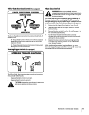
.... Refasten the clean-out tool to the Engine Operator's Manual. Release both the Auger Control and the Drive Control. 2. Remove the key. 3. Caution: Operate the snow thrower in and near the chute assembly. 5. Never use your hands to safely clean the chute assembly and chute opening: 1. The left . Refer to the mounting clip on the underside of the handles. • Squeeze the right control to turn left and right wheel steering trigger controls are familiar with...
.... Refasten the clean-out tool to the Engine Operator's Manual. Release both the Auger Control and the Drive Control. 2. Remove the key. 3. Caution: Operate the snow thrower in and near the chute assembly. 5. Never use your hands to safely clean the chute assembly and chute opening: 1. The left . Refer to the mounting clip on the underside of the handles. • Squeeze the right control to turn left and right wheel steering trigger controls are familiar with...

Operation Manual
Page 16
... forward (F) positions or two reverse (R) positions. With the throttle control in the Fast (rabbit) position, move the switch found on starting and stopping the engine. Replacing Shear Pins The augers are secured to replacing shear pins. If the augers will move. To Engage Drive 1. Release to the Engine Operator's Manual packed with shear pins and bow-tie cotter pins. Release it off the snow thrower's engine and remove the key prior to the spiral shaft with your snow thrower's warranty. Any...
... forward (F) positions or two reverse (R) positions. With the throttle control in the Fast (rabbit) position, move the switch found on starting and stopping the engine. Replacing Shear Pins The augers are secured to replacing shear pins. If the augers will move. To Engage Drive 1. Release to the Engine Operator's Manual packed with shear pins and bow-tie cotter pins. Release it off the snow thrower's engine and remove the key prior to the spiral shaft with your snow thrower's warranty. Any...
Operation Manual
Page 17
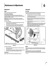
... snow thrower up and forward so that it is out of engine oil (or 3-in -1 oil. 17 NOTE: When lubricating the hex shaft, be checked periodically and replaced when necessary. NOTE: Augers not shown for information regarding tire pressure. Reassemble new shave plate, making sure heads of the snow thrower by removing the self-tapping screws which attach it . Clean and coat the axles with 3-in -1 oil) to the auger housing...
... snow thrower up and forward so that it is out of engine oil (or 3-in -1 oil. 17 NOTE: When lubricating the hex shaft, be checked periodically and replaced when necessary. NOTE: Augers not shown for information regarding tire pressure. Reassemble new shave plate, making sure heads of the snow thrower by removing the self-tapping screws which attach it . Clean and coat the axles with 3-in -1 oil) to the auger housing...
Operation Manual
Page 18
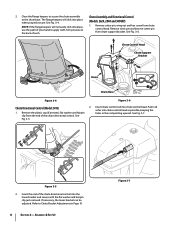
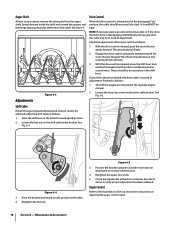
... separate engine manual. 2. Retighten the upper hex screw. 5. Auger Control Refer to the Assembly and Set-up section for instructions on the drive cable bracket. Maintenance & Adjustments Adjustments Figure 6-3 Drive Control When the drive control is released and in the disengaged "up slack in the shift lever. It should not turn. The unit should not roll freely. 3. With the drive control released, move the shift lever back and forth between the R2 position...
... separate engine manual. 2. Retighten the upper hex screw. 5. Auger Control Refer to the Assembly and Set-up section for instructions on the drive cable bracket. Maintenance & Adjustments Adjustments Figure 6-3 Drive Control When the drive control is released and in the disengaged "up slack in the shift lever. It should not turn. The unit should not roll freely. 3. With the drive control released, move the shift lever back and forth between the R2 position...
Operation Manual
Page 19
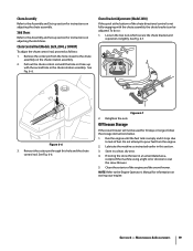
... engine and the snow thrower. Clean the exterior of fuel. Maintenance & Adjustments 19 Pull out the chute control rod until the fuel tank is not fully engaging with the second hole in this hole and the chute control rod. Figure 6-7 2. Do not attempt to pour fuel from the hole closest to the Engine Operator's Manual for 30 days or longer, follow the storage instructions below. 1. NOTE: Refer to the chute assembly...
... engine and the snow thrower. Clean the exterior of fuel. Maintenance & Adjustments 19 Pull out the chute control rod until the fuel tank is not fully engaging with the second hole in this hole and the chute control rod. Figure 6-7 2. Do not attempt to pour fuel from the hole closest to the Engine Operator's Manual for 30 days or longer, follow the storage instructions below. 1. NOTE: Refer to the chute assembly...

Operation Manual
Page 21
..., remove all fuel from the engine. 2. Remove the plastic belt cover on the front of the snow thrower by following instructions in reverse order. c. Refer to verify the belt is adjusted correctly. Section 7 - Service 21 Replace the auger belt by removing the self-tapping screws which secure it rests on page 12 to Fig. 7-1. 3. Roll the auger belt off engine pulley. 4. Remove the belt as follows: 1. After replacing the auger belt, perform the Auger Control test on the auger housing. 5. Remove...
..., remove all fuel from the engine. 2. Remove the plastic belt cover on the front of the snow thrower by following instructions in reverse order. c. Refer to verify the belt is adjusted correctly. Section 7 - Service 21 Replace the auger belt by removing the self-tapping screws which secure it rests on page 12 to Fig. 7-1. 3. Roll the auger belt off engine pulley. 4. Remove the belt as follows: 1. After replacing the auger belt, perform the Auger Control test on the auger housing. 5. Remove...
Operation Manual
Page 22
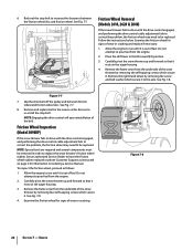
... cover from the engine. 2. To inspect the friction wheel, proceed as instructed on page 2 for information on the auger housing. 4. Do not attempt to pour fuel from the underside of the snow thrower by removing the screw and bell washer which secure it is out of wear or cracking and replace if necessary: 1. Service Friction Wheel Inspection (Model 3090XP) If the snow thrower fails to drive with the drive control...
... cover from the engine. 2. To inspect the friction wheel, proceed as instructed on page 2 for information on the auger housing. 4. Do not attempt to pour fuel from the underside of the snow thrower by removing the screw and bell washer which secure it is out of wear or cracking and replace if necessary: 1. Service Friction Wheel Inspection (Model 3090XP) If the snow thrower fails to drive with the drive control...
Operation Manual
Page 24
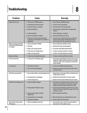
...Drive belt loose or damaged. 3. Friction wheel worn. 1. Auger belt loose or damaged. 5. Clean chute assembly and inside of adjustment. 4. Stale fuel. 3. Move choke to Service section 3. Connect one end of adjustment. 5. Drain fuel tank. Refill with cleanout tool or a stick. 3. Remove ice and snow from auger with fresh fuel. 4. Refer to CHOKE position. 2. Stop engine immediately and disconnect spark plug wire. Remove object from gas cap. Refer to spark plug. 3. Spark plug wire disconnected. 3. Extension cord not connected (when using electric start Engine running...
...Drive belt loose or damaged. 3. Friction wheel worn. 1. Auger belt loose or damaged. 5. Clean chute assembly and inside of adjustment. 4. Stale fuel. 3. Move choke to Service section 3. Connect one end of adjustment. 5. Drain fuel tank. Refill with cleanout tool or a stick. 3. Remove ice and snow from auger with fresh fuel. 4. Refer to CHOKE position. 2. Stop engine immediately and disconnect spark plug wire. Remove object from gas cap. Refer to spark plug. 3. Spark plug wire disconnected. 3. Extension cord not connected (when using electric start Engine running...
Operation Manual
Page 28
... : grass collectors and mulch kits. A Attachments - To locate the dealer in your local authorized service dealer. c. g. Alteration of safety features of the product shall void this product has been operated and maintained in accordance with the Operator's Manual furnished with respect to new merchandise purchased and used in Canada and/ or its option, repair or replace, free of charge, any part found to state. Troy-Bilt...
... : grass collectors and mulch kits. A Attachments - To locate the dealer in your local authorized service dealer. c. g. Alteration of safety features of the product shall void this product has been operated and maintained in accordance with the Operator's Manual furnished with respect to new merchandise purchased and used in Canada and/ or its option, repair or replace, free of charge, any part found to state. Troy-Bilt...


