
Service Manual
Page 1
FILE NO. 140-200519 (MFR'S VERSION A) SERVICE MANUAL COLOR TELEVISION/ VIDEO CASSETTE RECORDER/ DVD VIDEO PLAYER MW30G71 DOCUMENT CREATED IN JAPAN, July, 2005
FILE NO. 140-200519 (MFR'S VERSION A) SERVICE MANUAL COLOR TELEVISION/ VIDEO CASSETTE RECORDER/ DVD VIDEO PLAYER MW30G71 DOCUMENT CREATED IN JAPAN, July, 2005

Service Manual
Page 2
... J. USE OF CONTROLS, ADJUSTMENTS OR THE PERFORMANCE OF PROCEDURES OTHER THAN THOSE SPECIFIED HEREIN MAY RESULT IN HAZARDOUS RADIATION EXPOSURE. PREPARATION OF SERVICING The laser diode used . • A worker needs to protect against static electricity, be shortened. A1-1 Location of the required Marking... body. CAUTION THIS DIGITAL VIDEO PLAYER EMPLOYS A LASER SYSTEM. SHOULD THE UNIT REQUIRE MAINTENANCE, CONTACT AN AUTHORIZED SERVICE LOCATION-SEE SERVICE PROCEDURE. TO ENSURE PROPER USE OF THIS PRODUCT, PLEASE READ THIS SERVICE MANUAL CAREFULLY AND RETAIN FOR FUTURE REFERENCE.
... J. USE OF CONTROLS, ADJUSTMENTS OR THE PERFORMANCE OF PROCEDURES OTHER THAN THOSE SPECIFIED HEREIN MAY RESULT IN HAZARDOUS RADIATION EXPOSURE. PREPARATION OF SERVICING The laser diode used . • A worker needs to protect against static electricity, be shortened. A1-1 Location of the required Marking... body. CAUTION THIS DIGITAL VIDEO PLAYER EMPLOYS A LASER SYSTEM. SHOULD THE UNIT REQUIRE MAINTENANCE, CONTACT AN AUTHORIZED SERVICE LOCATION-SEE SERVICE PROCEDURE. TO ENSURE PROPER USE OF THIS PRODUCT, PLEASE READ THIS SERVICE MANUAL CAREFULLY AND RETAIN FOR FUTURE REFERENCE.
Service Manual
Page 3
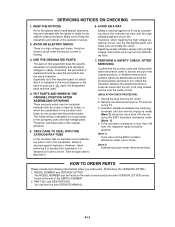
... on the TV. 3. Avoid an electric shock while the electric current is dangerous to service are put these do not contact with it in the operation manual. 2. PERFORM A SAFETY CHECK AFTER SERVICING Confirm that the screws, parts and wiring which were removed in the circuit diagram or ...the designated parts must be required. [Note 1] If you have the specific characters of parts as to keep the indications and notices in your SERVICE MANUAL. However, when removing it or serving from backward, it emits an X-ray from the AC outlet. 2. Unplug the plug from the cathoderay ...
... on the TV. 3. Avoid an electric shock while the electric current is dangerous to service are put these do not contact with it in the operation manual. 2. PERFORM A SAFETY CHECK AFTER SERVICING Confirm that the screws, parts and wiring which were removed in the circuit diagram or ...the designated parts must be required. [Note 1] If you have the specific characters of parts as to keep the indications and notices in your SERVICE MANUAL. However, when removing it or serving from backward, it emits an X-ray from the AC outlet. 2. Unplug the plug from the cathoderay ...

Service Manual
Page 5
...the volume at a moderate level. e. HEADPHONES When you to dangerous voltage or other equipment, turn on the product. d. DAMAGE REQUIRING SERVICE Unplug this indicates a need for the grounding electrode. 18. Unauthorized substitutions may cause serious personal injury and product malfunction. 31. These... discs are covered by a qualified technician to restore the unit to qualified service personnel. 19. Refer all of the laser beam. Read the owner's manual of the NEC that provides guidelines for a longtime. OUTDOOR ANTENNA GROUNDING If an outside antenna...
...the volume at a moderate level. e. HEADPHONES When you to dangerous voltage or other equipment, turn on the product. d. DAMAGE REQUIRING SERVICE Unplug this indicates a need for the grounding electrode. 18. Unauthorized substitutions may cause serious personal injury and product malfunction. 31. These... discs are covered by a qualified technician to restore the unit to qualified service personnel. 19. Refer all of the laser beam. Read the owner's manual of the NEC that provides guidelines for a longtime. OUTDOOR ANTENNA GROUNDING If an outside antenna...

Service Manual
Page 7
... equipment over the Pick Up Unit to prevent the Flux smoke from it. NOTE • Before your operation, please read "PREPARATION OF SERVICING". • Use the Lead Free solder. • Manual soldering conditions • Soldering temperature: 320 ± 20˚C • Soldering time: Within 3 seconds • Soldering combination: Sn-3.0Ag-0.5Cu •...
... equipment over the Pick Up Unit to prevent the Flux smoke from it. NOTE • Before your operation, please read "PREPARATION OF SERVICING". • Use the Lead Free solder. • Manual soldering conditions • Soldering temperature: 320 ± 20˚C • Soldering time: Within 3 seconds • Soldering combination: Sn-3.0Ag-0.5Cu •...

Service Manual
Page 18
...117.9lbs) 61.0kg (134.5lbs) A3-7 No - G-16 Accessories G-17 Interface G-18 Set Size G-19 Weight GENERAL SPECIFICATIONS Owner's Manual Language w/Guarantee Card Remote Control Unit Battery UM size x pcs OEM Brand Rod Antenna Poles Terminal Loop Antenna Terminal U/V Mixer 300 ohm to... Cord (2Pin-1Pin) Guarantee Card Registration Card ESP Card Warning Sheet Dew/AHC Caution Sheet Quick Set-up Sheet Circuit Diagram Service Facility List Important Safeguard Sheet Information (Return) Netflix Card Switch Front Power (Tact) Channel Up Channel Down Volume Up Volume ...
...117.9lbs) 61.0kg (134.5lbs) A3-7 No - G-16 Accessories G-17 Interface G-18 Set Size G-19 Weight GENERAL SPECIFICATIONS Owner's Manual Language w/Guarantee Card Remote Control Unit Battery UM size x pcs OEM Brand Rod Antenna Poles Terminal Loop Antenna Terminal U/V Mixer 300 ohm to... Cord (2Pin-1Pin) Guarantee Card Registration Card ESP Card Warning Sheet Dew/AHC Caution Sheet Quick Set-up Sheet Circuit Diagram Service Facility List Important Safeguard Sheet Information (Return) Netflix Card Switch Front Power (Tact) Channel Up Channel Down Volume Up Volume ...

Service Manual
Page 22
...Remove the 2 screws 1. 3. Remove the Operation PCB in the direction of arrow (A). 4. Before your operation, please read "PREPARATION OF SERVICING". 2. When Soldering/Removing of solder, use the drawing equipment over the Pick Up Unit to Fig. 1-11) NOTE Do not remove the...VCR Deck CP4501 CP4502 B1-3 3 CP3001 Bottom Plate Fig. 1-11 Remove the Front Shield in the direction of arrow (B). 6. Fig. 1-9 NOTE 1. Manual soldering conditions • Soldering temperature: 320 ± 20˚C • Soldering time: Within 3 seconds • Soldering combination: Sn-3.0Ag-0.5Cu 4. ...
...Remove the 2 screws 1. 3. Remove the Operation PCB in the direction of arrow (A). 4. Before your operation, please read "PREPARATION OF SERVICING". 2. When Soldering/Removing of solder, use the drawing equipment over the Pick Up Unit to Fig. 1-11) NOTE Do not remove the...VCR Deck CP4501 CP4502 B1-3 3 CP3001 Bottom Plate Fig. 1-11 Remove the Front Shield in the direction of arrow (B). 6. Fig. 1-9 NOTE 1. Manual soldering conditions • Soldering temperature: 320 ± 20˚C • Soldering time: Within 3 seconds • Soldering combination: Sn-3.0Ag-0.5Cu 4. ...
Service Manual
Page 39
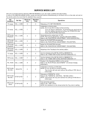
... 2 Adjusting of factory data. Refer to the "ELECTRICAL ADJUSTMENT" (PG SHIFTER). 2 Adjust the PG SHIFTER manually. The function will only work without the setting of MEMORY IC. SERVICE MODE LIST This unit is setting. Refer to the center position. DVD mode (No disc) STOP (DVD)... setting, the POWER ON total hours, and PLAY/REC total hours. 2 Horizontal position adjustment of factory on the remote control for data normal servicing. 2 If you can be opened. 3 Refer to the "ELECTRICAL ADJUSTMENT" (OSD HORIZONTAL). 2 Adjust the PG SHIFTER automatically. Refer to...
... 2 Adjusting of factory data. Refer to the "ELECTRICAL ADJUSTMENT" (PG SHIFTER). 2 Adjust the PG SHIFTER manually. The function will only work without the setting of MEMORY IC. SERVICE MODE LIST This unit is setting. Refer to the center position. DVD mode (No disc) STOP (DVD)... setting, the POWER ON total hours, and PLAY/REC total hours. 2 Horizontal position adjustment of factory on the remote control for data normal servicing. 2 If you can be opened. 3 Refer to the "ELECTRICAL ADJUSTMENT" (OSD HORIZONTAL). 2 Adjust the PG SHIFTER automatically. Refer to...


