

Service Manual
Page 5
.... A1-4 It may cause hearing or speaker damage. 27. DISC Do not use the headphones continuously with respect to proper grounding of the mast and supporting structure, grounding of the lead-in proper operating condition. 22. IMPORTANT SAFEGUARDS (CONTINUED) 17. Adjust only those that provides guidelines for a longtime. SOUND VOLUME Reduce...
.... A1-4 It may cause hearing or speaker damage. 27. DISC Do not use the headphones continuously with respect to proper grounding of the mast and supporting structure, grounding of the lead-in proper operating condition. 22. IMPORTANT SAFEGUARDS (CONTINUED) 17. Adjust only those that provides guidelines for a longtime. SOUND VOLUME Reduce...
Service Manual
Page 24
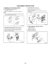
...(B) Link Unit Main Chassis 2-4: LINK LEVER/FLAP LEVER/BOT COVER (Refer to Fig. 2-3) 1. Remove the Flap Lever. NOTE 1. Extend the support 1. 2. DISASSEMBLY INSTRUCTIONS 2. Unlock the support 1. 3. Fig. 2-3 Main Chassis Cassette Side R Locker R Link Unit Cassette Side L Main Chassis Fig. 2-2 Flap Lever 1 Link Lever Fig.... 2-4 B2-1 Slide the 2 supports 2 and remove the Top Bracket. Remove the (A) side of the Top Bracket, bend the support 1 so that the Top Bracket is fixed. After the installation of the Link Unit first,...
...(B) Link Unit Main Chassis 2-4: LINK LEVER/FLAP LEVER/BOT COVER (Refer to Fig. 2-3) 1. Remove the Flap Lever. NOTE 1. Extend the support 1. 2. DISASSEMBLY INSTRUCTIONS 2. Unlock the support 1. 3. Fig. 2-3 Main Chassis Cassette Side R Locker R Link Unit Cassette Side L Main Chassis Fig. 2-2 Flap Lever 1 Link Lever Fig.... 2-4 B2-1 Slide the 2 supports 2 and remove the Top Bracket. Remove the (A) side of the Top Bracket, bend the support 1 so that the Top Bracket is fixed. After the installation of the Link Unit first,...

Service Manual
Page 25
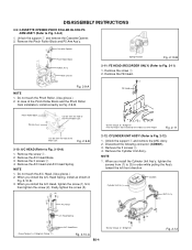
... wire. In case of Fig. 2-6-E. Loading Motor Fig. 2-5-B Fig. 2-6-B NOTE 1. Remove the screw 1. 2. Main Chassis Loading Motor Worm 2-6: TENSION ASS'Y (Refer to Fig. 2-5-A) 1. Unlock the support 2 and remove the Tension Arm Ass'y. 5. In case of the Tension Band installation, note the direction of Fig. 2-6-A to Fig. 2-6-C) 2. Remove the Worm. Turn the.... (Refer to move the Tension Arm Ass'y. 2. When installing the wires between Capstan DD Unit and Loading Motor, connect them correctly as Fig. 2-6-D. 3. Unlock the support 3 and remove the Tension Connect. 6.
... wire. In case of Fig. 2-6-E. Loading Motor Fig. 2-5-B Fig. 2-6-B NOTE 1. Remove the screw 1. 2. Main Chassis Loading Motor Worm 2-6: TENSION ASS'Y (Refer to Fig. 2-5-A) 1. Unlock the support 2 and remove the Tension Arm Ass'y. 5. In case of the Tension Band installation, note the direction of Fig. 2-6-A to Fig. 2-6-C) 2. Remove the Worm. Turn the.... (Refer to move the Tension Arm Ass'y. 2. When installing the wires between Capstan DD Unit and Loading Motor, connect them correctly as Fig. 2-6-D. 3. Unlock the support 3 and remove the Tension Connect. 6.

Service Manual
Page 26
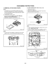
... S Reel and T Reel. 2. Remove the T Brake Spring. 2. Turn the T Brake Arm clockwise and bend the hook section to Fig. 2-8-B) 2. Remove the 2 Polyslider Washers 1. 3. Unlock the 2 supports 1 and remove the T Brake Band. And also set it . 3. B2-3 Big Hole (S Reel) [OK] Clutch Gear [NG] Clutch Gear Small Hole (T Reel) Fig. 2-8-B Idler Arm...
... S Reel and T Reel. 2. Remove the T Brake Spring. 2. Turn the T Brake Arm clockwise and bend the hook section to Fig. 2-8-B) 2. Remove the 2 Polyslider Washers 1. 3. Unlock the 2 supports 1 and remove the T Brake Band. And also set it . 3. B2-3 Big Hole (S Reel) [OK] Clutch Gear [NG] Clutch Gear Small Hole (T Reel) Fig. 2-8-B Idler Arm...
Service Manual
Page 27
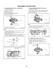
Do not touch the Pinch Roller. (Use gloves.) 2. Remove the screw 1. 2. Remove the A/C Head and A/C Head Spring. Unlock the support 1 and remove the AHC Ass'y. 2. Disconnect the following connector: (CD2001). 3. Fig. 2-9-B 2-10: A/C HEAD (Refer to Fig. 2-11) 1. Remove the screw 1. 2. Remove the A/C Head Base. 3. Do ... Ass'y. 1 Cassette Opener Pinch Roller Block P5 Arm Ass'y Main Chassis Fig. 2-9-A NOTE 1. When you install the A/C Head Spring, install as Fig. 2-9-B. NOTE 1. Unlock the support 1 and remove the Cassette Opener. 2.
Do not touch the Pinch Roller. (Use gloves.) 2. Remove the screw 1. 2. Remove the A/C Head and A/C Head Spring. Unlock the support 1 and remove the AHC Ass'y. 2. Disconnect the following connector: (CD2001). 3. Fig. 2-9-B 2-10: A/C HEAD (Refer to Fig. 2-11) 1. Remove the screw 1. 2. Remove the A/C Head Base. 3. Do ... Ass'y. 1 Cassette Opener Pinch Roller Block P5 Arm Ass'y Main Chassis Fig. 2-9-A NOTE 1. When you install the A/C Head Spring, install as Fig. 2-9-B. NOTE 1. Unlock the support 1 and remove the Cassette Opener. 2.

Service Manual
Page 29
... of the Cassette Guide Post installation, install correctly as the circled section of Guide Roller. 2. Do not touch the roller of Fig. 2-17-C. Unlock the support 1 and remove the Cassette Guide Post. 3. Remove the Clutch Lever. 4. DISASSEMBLY INSTRUCTIONS NOTE 1. Remove the LED Reflector. Cassette Guide Post 1 Loading Arm T Unit Loading Arm...
... of the Cassette Guide Post installation, install correctly as the circled section of Guide Roller. 2. Do not touch the roller of Fig. 2-17-C. Unlock the support 1 and remove the Cassette Guide Post. 3. Remove the Clutch Lever. 4. DISASSEMBLY INSTRUCTIONS NOTE 1. Remove the LED Reflector. Cassette Guide Post 1 Loading Arm T Unit Loading Arm...
Service Manual
Page 30
... the Main Chassis Ass'y. In case of the Main Chassis Ass'y, install it from the Main Frame Ass'y. 4. Unlock the 2 supports 1 and remove the Tray. 3-2: MAIN CHASSIS ASS'Y (Refer to the DISC REMOVAL METHOD AT NO POWER SUPPLY) 2. Disassemble only... that the each markers are needed if the disassembly is needed except listed parts, replace the DVD MECHA ASS'Y. 3-1: TRAY (Refer to Fig. 3-2-B) 2. Unlock the 2 supports 2. 3. Main Frame Ass'y (Bottom Side) (3) Rack Loading (3) (3) Traverse Holder (2) (1) Main Chassis Ass'y Tray Fig. 3-1-B (4) (4) Check Lock Main Frame Ass'y Fig. ...
... the Main Chassis Ass'y. In case of the Main Chassis Ass'y, install it from the Main Frame Ass'y. 4. Unlock the 2 supports 1 and remove the Tray. 3-2: MAIN CHASSIS ASS'Y (Refer to the DISC REMOVAL METHOD AT NO POWER SUPPLY) 2. Disassemble only... that the each markers are needed if the disassembly is needed except listed parts, replace the DVD MECHA ASS'Y. 3-1: TRAY (Refer to Fig. 3-2-B) 2. Unlock the 2 supports 2. 3. Main Frame Ass'y (Bottom Side) (3) Rack Loading (3) (3) Traverse Holder (2) (1) Main Chassis Ass'y Tray Fig. 3-1-B (4) (4) Check Lock Main Frame Ass'y Fig. ...
Service Manual
Page 31
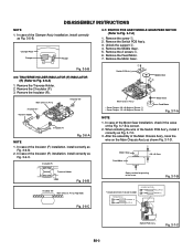
...Fig. 3-3-A NOTE 1. Main Frame Ass'y 21 Fig. 3-4-A NOTE 1. Press the Clamper and rotate the Clamper Plate clockwise, then unlock the 3 supports 1. 2. DISASSEMBLY INSTRUCTIONS 3-3: LOADING MOTOR PCB ASS'Y/ LOADING BELT (Refer to the Main Gear as shown the Fig. 3-4-B. In case of the ... Hook Loading Motor PCB Ass'y Fig. 3-3-C B3-2 Clamper Plate Clamper Magnet Rack Loading The Lever should be position between A and B. Unlock the support 2 and remove the Pulley Gear. 3. Remove the Loading Belt. 2. Remove the screw 1. 3. Press down the catcher 1 and slide the Rack...
...Fig. 3-3-A NOTE 1. Main Frame Ass'y 21 Fig. 3-4-A NOTE 1. Press the Clamper and rotate the Clamper Plate clockwise, then unlock the 3 supports 1. 2. DISASSEMBLY INSTRUCTIONS 3-3: LOADING MOTOR PCB ASS'Y/ LOADING BELT (Refer to the Main Gear as shown the Fig. 3-4-B. In case of the ... Hook Loading Motor PCB Ass'y Fig. 3-3-C B3-2 Clamper Plate Clamper Magnet Rack Loading The Lever should be position between A and B. Unlock the support 2 and remove the Pulley Gear. 3. Remove the Loading Belt. 2. Remove the screw 1. 3. Press down the catcher 1 and slide the Rack...
Service Manual
Page 32
... the Insulator (R) installation, install correctly as Fig. 3-7-C. 3. Remove the screw 1. 2. Remove the 2 screws 3. 6. Main Chassis Ass'y Insulator (R) Insulator (F) Traverse Holder Insulator (F) Fig. 3-6-A NOTE 1. Unlock the support 2. 4. Remove the Feed Motor. 7. Remove the Motor Gear. In case of the Motor Gear installation, check if the value of the insert. Motor Gear Feed...
... the Insulator (R) installation, install correctly as Fig. 3-7-C. 3. Remove the screw 1. 2. Remove the 2 screws 3. 6. Main Chassis Ass'y Insulator (R) Insulator (F) Traverse Holder Insulator (F) Fig. 3-6-A NOTE 1. Unlock the support 2. 4. Remove the Feed Motor. 7. Remove the Motor Gear. In case of the Motor Gear installation, check if the value of the insert. Motor Gear Feed...
Service Manual
Page 34
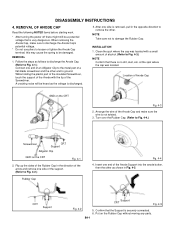
... of an Alligator Clip to the metal part of a flat-blade screwdriver and the other end to damage the Rubber Cap. Location of the Anode Support into the anode button, then the other . Insert one end of Anode Cap GND on the Rubber Cap without moving any parts. NOTE Take care... the other as the voltage is no dirt, dust, etc. While holding the plastic part of the insulated Screwdriver, touch the support of the Anode with a small amount of the support. (Refer to Fig. 4-2.) Rubber Cap Fig. 4-4 4. Flip up the sides of the arrow and remove one side is not twisted. 3. CRT...
... of an Alligator Clip to the metal part of a flat-blade screwdriver and the other end to damage the Rubber Cap. Location of the Anode Support into the anode button, then the other . Insert one end of Anode Cap GND on the Rubber Cap without moving any parts. NOTE Take care... the other as the voltage is no dirt, dust, etc. While holding the plastic part of the insulated Screwdriver, touch the support of the Anode with a small amount of the support. (Refer to Fig. 4-2.) Rubber Cap Fig. 4-4 4. Flip up the sides of the arrow and remove one side is not twisted. 3. CRT...


