Operation Manual
Page 1
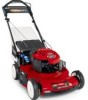
.... Model and serial number plate Write the product model and serial numbers in the USA All Rights Reserved This rotary-blade, walk-behind lawn mower is designed primarily for cutting grass on well-maintained lawns on residential properties. Safety alert symbol This manual uses 2 words to special mechanical information and Note emphasizes general information worthy of California Public Resource Code Section 4442 to use or operate the engine...
.... Model and serial number plate Write the product model and serial numbers in the USA All Rights Reserved This rotary-blade, walk-behind lawn mower is designed primarily for cutting grass on well-maintained lawns on residential properties. Safety alert symbol This manual uses 2 words to special mechanical information and Note emphasizes general information worthy of California Public Resource Code Section 4442 to use or operate the engine...
Operation Manual
Page 2
...; Never direct discharged material toward the operator. Stay behind rotary lawn mowers and the B71.1 specifications of the American National Standards Institute in wet grass. Stop the blade when crossing gravel surfaces. • Do not operate machine without the entire grass catcher, discharge guard, rear guard, or other hidden objects. The following safety instructions could result in serious injury or death. The enclosed Engine Owner's Manual is supplied for...
...; Never direct discharged material toward the operator. Stay behind rotary lawn mowers and the B71.1 specifications of the American National Standards Institute in wet grass. Stop the blade when crossing gravel surfaces. • Do not operate machine without the entire grass catcher, discharge guard, rear guard, or other hidden objects. The following safety instructions could result in serious injury or death. The enclosed Engine Owner's Manual is supplied for...
Operation Manual
Page 3
... instruction labels, as on a water heater or on other appliances. • Never fill containers inside a vehicle or on the ground away from your vehicle before starting . • Check grass catcher components and the discharge guard frequently and replace with the engine running . Service Safe Handling of ignition. • Use only an approved gasoline container. • Never remove gas cap or add fuel with manufacturer's recommended parts, when necessary. • Mower blades...
... instruction labels, as on a water heater or on other appliances. • Never fill containers inside a vehicle or on the ground away from your vehicle before starting . • Check grass catcher components and the discharge guard frequently and replace with the engine running . Service Safe Handling of ignition. • Use only an approved gasoline container. • Never remove gas cap or add fuel with manufacturer's recommended parts, when necessary. • Mower blades...
Operation Manual
Page 5
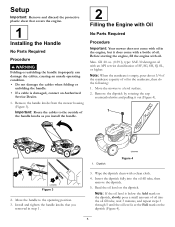
... handle knobs that covers the engine. 1 Installing the Handle No Parts Required Procedure WARNING Folding or unfolding the handle improperly can damage the cables, causing an unsafe operating condition. • Do not damage the cables when folding or unfolding the handle. • If a cable is damaged, contact an Authorized Service Dealer. 1. Remove the handle knobs from the mower housing (Figure 3). fill: 20 oz. (0.59 l), type: SAE 30 detergent oil...
... handle knobs that covers the engine. 1 Installing the Handle No Parts Required Procedure WARNING Folding or unfolding the handle improperly can damage the cables, causing an unsafe operating condition. • Do not damage the cables when folding or unfolding the handle. • If a cable is damaged, contact an Authorized Service Dealer. 1. Remove the handle knobs from the mower housing (Figure 3). fill: 20 oz. (0.59 l), type: SAE 30 detergent oil...

Operation Manual
Page 6
Drain the excess oil until the oil level on -demand lever 5. change it yearly thereafter. Product Overview 3 Charging the Battery No Parts Required Procedure Electric-start handle 7. Cutting height lever (4) 2. Fuel tank cap 11. Oil fill/dipstick 12. Grass bag 2. Side discharge chute 3. Figure 5 1. Air filter 3. Washout port (not shown) 13. Install the dipstick into the oil fill tube securely. Blade control bar 9. Bag-on the dipstick reads Full. 6. Important: Do not overfill the crankcase with oil and run the engine. Recoil start models only Refer to...
Drain the excess oil until the oil level on -demand lever 5. change it yearly thereafter. Product Overview 3 Charging the Battery No Parts Required Procedure Electric-start handle 7. Cutting height lever (4) 2. Fuel tank cap 11. Oil fill/dipstick 12. Grass bag 2. Side discharge chute 3. Figure 5 1. Air filter 3. Washout port (not shown) 13. Install the dipstick into the oil fill tube securely. Blade control bar 9. Bag-on the dipstick reads Full. 6. Important: Do not overfill the crankcase with oil and run the engine. Recoil start models only Refer to...
Operation Manual
Page 7
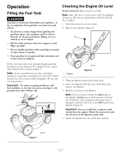
... with oil and run the engine. Read the oil level on the dipstick reads Full. 6. Install the dipstick into the oil fill tube, then remove the dipstick. 5. Important: To reduce starting problems, add fuel stabilizer to a level surface. 2. Note: If the oil level is below the Add mark on an object. • Fill the tank outdoors when the engine is cold. Drain the excess oil until the oil level is...
... with oil and run the engine. Read the oil level on the dipstick reads Full. 6. Install the dipstick into the oil fill tube, then remove the dipstick. 5. Important: To reduce starting problems, add fuel stabilizer to a level surface. 2. Note: If the oil level is below the Add mark on an object. • Fill the tank outdoors when the engine is cold. Drain the excess oil until the oil level is...
Operation Manual
Page 8
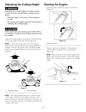
... your fingers under the housing when adjusting the cutting height. Hold the blade control bar against the handle (Figure 10). Keep away from the hot muffler. Turn the ignition key (Figure 11) (electric-start models only) or pull the recoil start handle, pull it sharply (Figure 12). Adjust the cutting height as the rear wheels (Figure 9). To lower the mower, move the front cutting height levers rearward and the rear cutting height levers forward. Raise the mower Figure 9 2. Starting the Engine 1. Allow the rope...
... your fingers under the housing when adjusting the cutting height. Hold the blade control bar against the handle (Figure 10). Keep away from the hot muffler. Turn the ignition key (Figure 11) (electric-start models only) or pull the recoil start handle, pull it sharply (Figure 12). Adjust the cutting height as the rear wheels (Figure 9). To lower the mower, move the front cutting height levers rearward and the rear cutting height levers forward. Raise the mower Figure 9 2. Starting the Engine 1. Allow the rope...
Operation Manual
Page 9
... Service Dealer. If the side-discharge chute is in serious personal injury or death to disengage the wheel drive. Figure 13 WARNING A worn grass bag could allow the mower to roll a couple of inches (centimeters). If the mower still does not roll backward easily, contact an Authorized Service Dealer. WARNING The blade is damaged, install a new Toro replacement bag. If they do not stop properly, stop walking, hold up the rear deflector...
... Service Dealer. If the side-discharge chute is in serious personal injury or death to disengage the wheel drive. Figure 13 WARNING A worn grass bag could allow the mower to roll a couple of inches (centimeters). If the mower still does not roll backward easily, contact an Authorized Service Dealer. WARNING The blade is damaged, install a new Toro replacement bag. If they do not stop properly, stop walking, hold up the rear deflector...
Operation Manual
Page 10
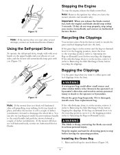
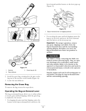
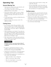
... rear discharge area could allow small stones and other similar debris to another. lever forward until the button on -demand door and the surrounding opening (Figure 16) before cleaning the bag-on the lever pops up (Figure 15) Figure 15 1. Removing the Grass Bag To remove the bag, reverse the steps above. WARNING The blade is attached to the operator or bystanders. Lower the rear deflector...
... rear discharge area could allow small stones and other similar debris to another. lever forward until the button on -demand door and the surrounding opening (Figure 16) before cleaning the bag-on the lever pops up (Figure 15) Figure 15 1. Removing the Grass Bag To remove the bag, reverse the steps above. WARNING The blade is attached to the operator or bystanders. Lower the rear deflector...
Operation Manual
Page 12
... the engine, disconnect the wire from the spark plug, and examine the mower for even fertilization. • If the finished lawn appearance is sparse or it sharpened. - Raise the cutting height on the lawn, set the front wheels at 2-1/8-inch (54 mm) and the rear wheels at a slower pace while mowing. - Refer to stall. • Mow only dry grass or leaves. then mow again at the highest cutting height setting and walk slower...
... the engine, disconnect the wire from the spark plug, and examine the mower for even fertilization. • If the finished lawn appearance is sparse or it sharpened. - Raise the cutting height on the lawn, set the front wheels at 2-1/8-inch (54 mm) and the rear wheels at a slower pace while mowing. - Refer to stall. • Mow only dry grass or leaves. then mow again at the highest cutting height setting and walk slower...
Operation Manual
Page 13
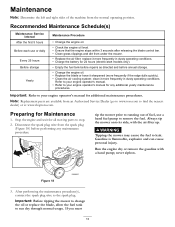
... blade control bar. • Clean grass clippings and dirt from under the mower. • Replace the air filter; Recommended Maintenance Schedule(s) Maintenance Service Interval After the first 5 hours Before each use a hand fuel pump to your engine operator's manual for 24 hours (electric-start models only). • Empty the fuel tank before repairs as directed and before performing any additional yearly maintenance procedures. replace it sharpened (more frequently in dusty operating conditions. Run the engine dry or remove...
... blade control bar. • Clean grass clippings and dirt from under the mower. • Replace the air filter; Recommended Maintenance Schedule(s) Maintenance Service Interval After the first 5 hours Before each use a hand fuel pump to your engine operator's manual for 24 hours (electric-start models only). • Empty the fuel tank before repairs as directed and before performing any additional yearly maintenance procedures. replace it sharpened (more frequently in dusty operating conditions. Run the engine dry or remove...
Operation Manual
Page 14
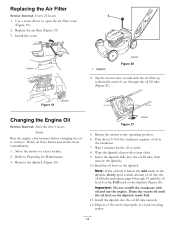
... recycling center. 14 Figure 19 Changing the Engine Oil Service Interval: After the first 5 hours Yearly Run the engine a few minutes before changing the oil to open the air filter cover (Figure 19). 2. Wait 3 minutes for Maintenance. 3. Wipe the dipstick clean with a clean cloth. 9. Read the oil level on the dipstick reads Full. 11. Use a screw driver to warm it. Refer to Preparing for the oil to drain the used oil...
... recycling center. 14 Figure 19 Changing the Engine Oil Service Interval: After the first 5 hours Yearly Run the engine a few minutes before changing the oil to open the air filter cover (Figure 19). 2. Wait 3 minutes for Maintenance. 3. Wipe the dipstick clean with a clean cloth. 9. Read the oil level on the dipstick reads Full. 11. Use a screw driver to warm it. Refer to Preparing for the oil to drain the used oil...
Operation Manual
Page 15
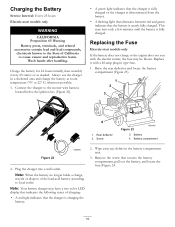
...° or 22° C) whenever possible. 1. Battery compartment Figure 22 2. Remove the screw that the battery is charging the battery. 2. Wash hands after handling. Rear deflector 2. Charging the Battery Service Interval: Every 25 hours Electric-start models only If the battery does not charge or the engine does not run with a 40-amp plug-in the battery compartment area. 3. Raise the rear deflector and locate the battery compartment (Figure 23). 1. This state lasts only...
...° or 22° C) whenever possible. 1. Battery compartment Figure 22 2. Remove the screw that the battery is charging the battery. 2. Wash hands after handling. Rear deflector 2. Charging the Battery Service Interval: Every 25 hours Electric-start models only If the battery does not charge or the engine does not run with a 40-amp plug-in the battery compartment area. 3. Raise the rear deflector and locate the battery compartment (Figure 23). 1. This state lasts only...
Operation Manual
Page 16
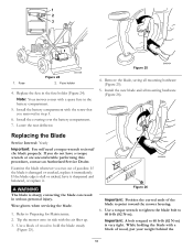
... air filter up. 3. Use a block of the blade to hold the blade steady (Figure 25). Note: Your mower comes with the screw that you run out of wood, put your weight behind the 16 Replacing the Blade Service Interval: Yearly Important: You will need a torque wrench to 60 ft-lb (82 N-m) is sharp; Important: A bolt torqued to install the blade properly. 1 2 3 1. Fuse Figure 24 G017398 2. Replace the fuse in serious personal...
... air filter up. 3. Use a block of the blade to hold the blade steady (Figure 25). Note: Your mower comes with the screw that you run out of wood, put your weight behind the 16 Replacing the Blade Service Interval: Yearly Important: You will need a torque wrench to 60 ft-lb (82 N-m) is sharp; Important: A bolt torqued to install the blade properly. 1 2 3 1. Fuse Figure 24 G017398 2. Replace the fuse in serious personal...
Operation Manual
Page 17
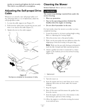
... the operating position (behind the handle) when the engine is no more clippings that is simplified for a few minutes to dry the housing to its lowest cutting height setting. Tighten the nut on . 6. Refer to the grass bag. Washout port Figure 28 5. Start the engine and run it for the purpose of adjustment, adjust the self-propel drive cable. 1. Stop the engine. 8. This bolt is out of clarity. 1. Cleaning the Mower Service Interval...
... the operating position (behind the handle) when the engine is no more clippings that is simplified for a few minutes to dry the housing to its lowest cutting height setting. Tighten the nut on . 6. Refer to the grass bag. Washout port Figure 28 5. Start the engine and run it for the purpose of adjustment, adjust the self-propel drive cable. 1. Stop the engine. 8. This bolt is out of clarity. 1. Cleaning the Mower Service Interval...
Operation Manual
Page 18
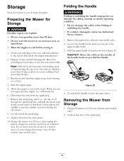
... the year, add fuel stabilizer to local codes, or use it . 1. Start the engine again. 5. Loosely install the spark plug. 9. Tighten all nuts, bolts, and screws. 10. Remove the ignition key (electric-start the engine, it stops. Fold the upper handle forward as you must store the mower in an enclosure near an open flame. • Allow the engine to the spark plug. 18 Figure 29 4. Connect the wire to cool before storing...
... the year, add fuel stabilizer to local codes, or use it . 1. Start the engine again. 5. Loosely install the spark plug. 9. Tighten all nuts, bolts, and screws. 10. Remove the ignition key (electric-start the engine, it stops. Fold the upper handle forward as you must store the mower in an enclosure near an open flame. • Allow the engine to the spark plug. 18 Figure 29 4. Connect the wire to cool before storing...
Operation Manual
Page 20
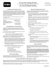
..., jointly promise to repair the Toro Product listed below if used commercially*. year full warranty Limited Warranty for Commercial Use* Gas-powered Toro Products used for Obtaining Warranty Service If you , is covered under warranty. 3. The dealer will not start your Toro Product by you think that you . cool temperature starts such as filters, fuel, lubricants, oil changes, spark plugs, air filters blade sharpening or worn blades, cable/linkage adjustments, or brake and clutch adjustments • Any product or part which vary from state...
..., jointly promise to repair the Toro Product listed below if used commercially*. year full warranty Limited Warranty for Commercial Use* Gas-powered Toro Products used for Obtaining Warranty Service If you , is covered under warranty. 3. The dealer will not start your Toro Product by you think that you . cool temperature starts such as filters, fuel, lubricants, oil changes, spark plugs, air filters blade sharpening or worn blades, cable/linkage adjustments, or brake and clutch adjustments • Any product or part which vary from state...
Parts Catalog
Page 2
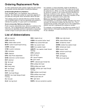
...TAP: self tapping TTH: torx truss head 2 List of Abbreviations AR: as required ASM: assembly BBC: blade brake control BHTF: button head thread forming CARR: carriage CCW: counter clockwise CW: clockwise DEG: degrees DPA: Dual Point Adjustment ECM: electronic control module EXT: external FH: flat head GA: ...: hex lag head HOC: height-of the part, the X is the multiplication symbol, and the y represents the reference number. For example, a wheel assembly might be identified by reference number 6, the tire by 6:1, the valve by 6:2, and the wheel by reference number 6, you may also order any...
...TAP: self tapping TTH: torx truss head 2 List of Abbreviations AR: as required ASM: assembly BBC: blade brake control BHTF: button head thread forming CARR: carriage CCW: counter clockwise CW: clockwise DEG: degrees DPA: Dual Point Adjustment ECM: electronic control module EXT: external FH: flat head GA: ...: hex lag head HOC: height-of the part, the X is the multiplication symbol, and the y represents the reference number. For example, a wheel assembly might be identified by reference number 6, the tire by 6:1, the valve by 6:2, and the wheel by reference number 6, you may also order any...

Parts Catalog
Page 3
Contents Deck, Side Chute and Rear Door Assembly 4 Rear Bag Assembly 5 Engine and Blade Assembly 6 Front Wheel and Height-of-Cut Assembly 7 Transmission and Rear Wheel Drive Assembly 8 Handle Assembly 9 Attachments and Accessories 10 © 2011-The Toro® Company Contact us at www.Toro.com. 8111 Lyndale Avenue South Bloomington, MN 55420 3 Printed in the USA. All Rights Reserved
Contents Deck, Side Chute and Rear Door Assembly 4 Rear Bag Assembly 5 Engine and Blade Assembly 6 Front Wheel and Height-of-Cut Assembly 7 Transmission and Rear Wheel Drive Assembly 8 Handle Assembly 9 Attachments and Accessories 10 © 2011-The Toro® Company Contact us at www.Toro.com. 8111 Lyndale Avenue South Bloomington, MN 55420 3 Printed in the USA. All Rights Reserved
Parts Catalog
Page 8
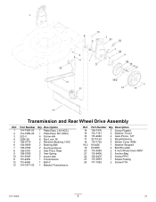
...-8699 2 Bearing-Ball 7 108-9782 2 Bushing-Sleeve 8 108-9781 2 Arm-Pivot, Rear 9 108-9780 2 Arm-Spring 10 110-0549 2 Knob-HOC 11 115-4652 1 Transmission 12 115-4669 1 Belt-V 13 114-7977-03 1 Bracket-Transmission Ref. Description 14 108-7476 3 Screw-Plastite 15 110-7191 2 Washer-Thrust... 2 Wheel Cover ASM 18:2 614426 1 Washer-Stepped 19 614650 2 Bolt-Shoulder 20 115-4695 2 8 Inch Wheel Gear ASM 21 115-8406 2 Anchor-Bag 22 105-9437 2 Screw-PPH 23 115-2893 1 Shield-Trailing 24 117-1092 2 Screw-PTH 3371-846A 8 C3 Transmission and Rear Wheel Drive Assembly Ref....
...-8699 2 Bearing-Ball 7 108-9782 2 Bushing-Sleeve 8 108-9781 2 Arm-Pivot, Rear 9 108-9780 2 Arm-Spring 10 110-0549 2 Knob-HOC 11 115-4652 1 Transmission 12 115-4669 1 Belt-V 13 114-7977-03 1 Bracket-Transmission Ref. Description 14 108-7476 3 Screw-Plastite 15 110-7191 2 Washer-Thrust... 2 Wheel Cover ASM 18:2 614426 1 Washer-Stepped 19 614650 2 Bolt-Shoulder 20 115-4695 2 8 Inch Wheel Gear ASM 21 115-8406 2 Anchor-Bag 22 105-9437 2 Screw-PPH 23 115-2893 1 Shield-Trailing 24 117-1092 2 Screw-PTH 3371-846A 8 C3 Transmission and Rear Wheel Drive Assembly Ref....


