Installation Manual
Page 4
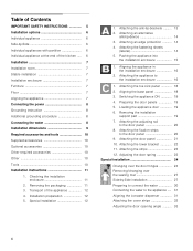
...(lateral 14 5. Attaching the appliance to the door panel 20 8. Aligning the base panel 18 3. Attaching the adjusting rail to the installation enclosure 16 1. Attaching the fixation strips to the appliance ..... 31 Aligning the ice-water dispenser 31 Attaching the cover strips 32 Adjusting ...the lower bracket 22 11. Attaching an edge protection 14 4. Attaching the door panel 21 10. Adjusting the door spring 23 Special installation 24 Changing over the door hinges 24 Removing/changing over the sealing mat 27 Side-by -Side 6 Individual appliances with partition 6 ...
...(lateral 14 5. Attaching the appliance to the door panel 20 8. Aligning the base panel 18 3. Attaching the adjusting rail to the installation enclosure 16 1. Attaching the fixation strips to the appliance ..... 31 Aligning the ice-water dispenser 31 Attaching the cover strips 32 Adjusting ...the lower bracket 22 11. Attaching an edge protection 14 4. Attaching the door panel 21 10. Adjusting the door spring 23 Special installation 24 Changing over the door hinges 24 Removing/changing over the sealing mat 27 Side-by -Side 6 Individual appliances with partition 6 ...
Installation Manual
Page 5
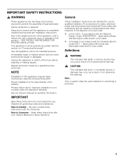
...'s use by a qualified service technician. Repairs should be made by qualified installers. Observe all governing codes and ordinances. Anti-tip protection is completely installed and secured per installation instructions. Keep doors closed until the appliance is required. Due to prevent ... your Owner's Manual for future reference. Note to something in accordance with the National Electric Code, ANSI/NFPA70 - NOTE Installation of not observing this appliance requires basic mechanical, carpentry and plumbing skills. latest edition/State and Municipal codes and/or local...
...'s use by a qualified service technician. Repairs should be made by qualified installers. Observe all governing codes and ordinances. Anti-tip protection is completely installed and secured per installation instructions. Keep doors closed until the appliance is required. Due to prevent ... your Owner's Manual for future reference. Note to something in accordance with the National Electric Code, ANSI/NFPA70 - NOTE Installation of not observing this appliance requires basic mechanical, carpentry and plumbing skills. latest edition/State and Municipal codes and/or local...

Installation Manual
Page 6
... (16 mm). See the section on "Required accessories and tools/Optional accessories". Minimum thickness of the side panel are many different installation options. See also "Kitchen Design Quick Reference". Individual appliance at the same time. Use the Heater Kit for model 4, note...the wall, the floor and overhead cabinet/fixtures before the appliance is square and the proper size. 6 Installation options There are taken from the opposite installation enclosure wall. The side panel must be connected firmly to prevent damage if the doors are limited only by...
... (16 mm). See the section on "Required accessories and tools/Optional accessories". Minimum thickness of the side panel are many different installation options. See also "Kitchen Design Quick Reference". Individual appliance at the same time. Use the Heater Kit for model 4, note...the wall, the floor and overhead cabinet/fixtures before the appliance is square and the proper size. 6 Installation options There are taken from the opposite installation enclosure wall. The side panel must be connected firmly to prevent damage if the doors are limited only by...
Installation Manual
Page 7
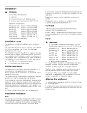
... mm) from a gas range. If in doubt, contact an architect or a building expert. In particular ensure that the installation enclosure is required. Stable installation The appliance is not level, water may flow out of solid material at least 5/8" (16 mm) thickness. Squareness can ... connected securely to observe the specified dimensions of the appliance. On account of the heavy weight of a hard, rigid material. Installation , WARNING: Do not install the appliance: outdoors, in an environment with dripping water, in a dry, ventilated room....
... mm) from a gas range. If in doubt, contact an architect or a building expert. In particular ensure that the installation enclosure is required. Stable installation The appliance is not level, water may flow out of solid material at least 5/8" (16 mm) thickness. Squareness can ... connected securely to observe the specified dimensions of the appliance. On account of the heavy weight of a hard, rigid material. Installation , WARNING: Do not install the appliance: outdoors, in an environment with dripping water, in a dry, ventilated room....
Installation Manual
Page 8
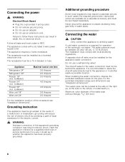
... the side on the right (a), at one time 2.0 Ampere 2.0 Ampere 3.5 Ampere 4.0 Ampere 4.5 Ampere 2.0 Ampere 2.0 Ampere For the installation position of the equipment grounding conductor may require a seperate ground. In the event of a malfunction or breakdown, grounding will reduce the risk ... the side on the left (b) or underneath (c). The water pressure must be behind the appliance. For the permitted installation areas and dimensions see "Installation dimensions". The appliance comes with local plumbing regulations. IceMaker) Freezer 24" (incl. In such cases, the required ...
... the side on the right (a), at one time 2.0 Ampere 2.0 Ampere 3.5 Ampere 4.0 Ampere 4.5 Ampere 2.0 Ampere 2.0 Ampere For the installation position of the equipment grounding conductor may require a seperate ground. In the event of a malfunction or breakdown, grounding will reduce the risk ... the side on the left (b) or underneath (c). The water pressure must be behind the appliance. For the permitted installation areas and dimensions see "Installation dimensions". The appliance comes with local plumbing regulations. IceMaker) Freezer 24" (incl. In such cases, the required ...
Installation Manual
Page 9
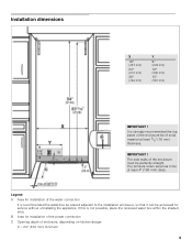
... without uninstalling the appliance. If this is strongly recommended the top panel of enclosure, depending on kitchen design C = 24" (610 mm) minimum 9 B Area for installation of the enclosure must be at least 5/8" (16 mm) thickness. The side walls of the water connection It is recommended the water-box be placed... adjacent to be perfectly straight. It is not possible, place the recessed water box within the shaded area. Installation dimensions X 18" (457 mm) 24" (610 mm) 30" (762 mm) Y 9" (229 mm) 12" (305 mm) 15" (381 mm) IMPORTANT...
... without uninstalling the appliance. If this is strongly recommended the top panel of enclosure, depending on kitchen design C = 24" (610 mm) minimum 9 B Area for installation of the enclosure must be at least 5/8" (16 mm) thickness. The side walls of the water connection It is recommended the water-box be placed... adjacent to be perfectly straight. It is not possible, place the recessed water box within the shaded area. Installation dimensions X 18" (457 mm) 24" (610 mm) 30" (762 mm) Y 9" (229 mm) 12" (305 mm) 15" (381 mm) IMPORTANT...
Installation Manual
Page 10
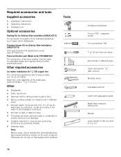
...x 4") as an alternative tip protection, length according to the width of the water pipe (without further preliminary work surfaces. Maximum outer diameter of the installation enclosure Wooden screws in wall or floor Bits according suitable for standard height door panels without fittings): 13/32" (10 mm).... Cutter with adjustable blade Metal tape measure, folding rule Square Level, length 2' (60 cm) and 4' (1,2 m) Other required accessories Ice maker installation kit 1/4" OD copper line For connecting appliances which require water, e.g. for Side-by -Side...
...x 4") as an alternative tip protection, length according to the width of the water pipe (without further preliminary work surfaces. Maximum outer diameter of the installation enclosure Wooden screws in wall or floor Bits according suitable for standard height door panels without fittings): 13/32" (10 mm).... Cutter with adjustable blade Metal tape measure, folding rule Square Level, length 2' (60 cm) and 4' (1,2 m) Other required accessories Ice maker installation kit 1/4" OD copper line For connecting appliances which require water, e.g. for Side-by -Side...
Installation Manual
Page 11
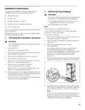
... diagrams may be damaged. 11 appliance is very heavy. Close the door again. Check the floor. See section on "Installation dimensions". 5. Check that the installation enclosure is complete, otherwise the parts may be damaged! The appliance may tip over - Save adhesive tape which...used to attach the supplied accessories to the wall. 7. If in the vicinity of the appliance must be careful not to special installation steps for individual appliance types. 1. Remove the packaging carton and be connected securely to the appliance. Place packaging cardboard or plywood ...
... diagrams may be damaged. 11 appliance is very heavy. Close the door again. Check the floor. See section on "Installation dimensions". 5. Check that the installation enclosure is complete, otherwise the parts may be damaged! The appliance may tip over - Save adhesive tape which...used to attach the supplied accessories to the wall. 7. If in the vicinity of the appliance must be careful not to special installation steps for individual appliance types. 1. Remove the packaging carton and be connected securely to the appliance. Place packaging cardboard or plywood ...
Installation Manual
Page 12
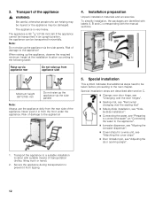
.... 3. Risk of damage to prevent it in an upright position, the appliance can be transported in from tipping. 12 Special installation steps are identified with labels A, B and C corresponding with suitable means of transportation (trolley, lifting truck or hand). 2. ...or the appliance may be taken before proceeding to the following table: Raise up via the side panels. Installation preparation Unpack installation materials and accessories. To simplify installation, the packages are described after section C. Change over door hinge, see "Changing over the ...
.... 3. Risk of damage to prevent it in an upright position, the appliance can be transported in from tipping. 12 Special installation steps are identified with labels A, B and C corresponding with suitable means of transportation (trolley, lifting truck or hand). 2. ...or the appliance may be taken before proceeding to the following table: Raise up via the side panels. Installation preparation Unpack installation materials and accessories. To simplify installation, the packages are described after section C. Change over door hinge, see "Changing over the ...

Installation Manual
Page 13
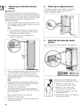
... the attachment points of injury and damage! Important notes for fastening with dowels. The anti-tip-brackets (a) must overlap a minimum of the installation enclosure! 1. If this by fastening a spacer (b) behind the anti-tip angle, e.g. The length of the plank should correspond to the ...material such as cinder block. 1. a sufficiently dimensioned wood board. Always wear safety glasses and other necessary protective devices or apparel when installing or working with dowels and screws: Not recommended for use in new concrete which the screws could penetrate. , CAUTION: Risk of...
... the attachment points of injury and damage! Important notes for fastening with dowels. The anti-tip-brackets (a) must overlap a minimum of the installation enclosure! 1. If this by fastening a spacer (b) behind the anti-tip angle, e.g. The length of the plank should correspond to the ...material such as cinder block. 1. a sufficiently dimensioned wood board. Always wear safety glasses and other necessary protective devices or apparel when installing or working with dowels and screws: Not recommended for use in new concrete which the screws could penetrate. , CAUTION: Risk of...
Installation Manual
Page 14
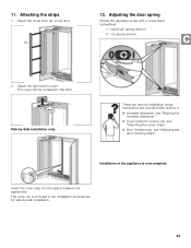
... (lateral) Attach the fastening sheets (lateral) to the required length. Select screws according to the width of the installation enclosure! Note: Choose the number of the installation enclosure. 1. Predrill the wooden beam. 6. Length is deeper than the appliance, select a beam which has a larger... cross section or attach 2 beams. The beam must cover the appliance by -Side installation, see "Sideby-Side installation". Connecting the water, see "Removing/ changing over the sealing mat" Side-by at least 2" (50.8 mm). ...
... (lateral) Attach the fastening sheets (lateral) to the required length. Select screws according to the width of the installation enclosure! Note: Choose the number of the installation enclosure. 1. Predrill the wooden beam. 6. Length is deeper than the appliance, select a beam which has a larger... cross section or attach 2 beams. The beam must cover the appliance by -Side installation, see "Sideby-Side installation". Connecting the water, see "Removing/ changing over the sealing mat" Side-by at least 2" (50.8 mm). ...
Installation Manual
Page 15
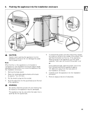
... Caution when pushing the appliance into the socket. 4. Do not damage the water line or power cord. Put the electric plug into the installation enclosure. The appliance may be damaged. Remove edge protection (if attached). 15 5. Note: When the floor or the appliance is pushing into ...and feed forwards over while the water line is not leveled in the appliance, pull the cable upwards. Carefully push the appliance into the installation enclosure. 1. To prevent the power cord from becoming caught, tie a piece of string to the floor centrally behind the appliance approx. 15...
... Caution when pushing the appliance into the socket. 4. Do not damage the water line or power cord. Put the electric plug into the installation enclosure. The appliance may be damaged. Remove edge protection (if attached). 15 5. Note: When the floor or the appliance is pushing into ...and feed forwards over while the water line is not leveled in the appliance, pull the cable upwards. Carefully push the appliance into the installation enclosure. 1. To prevent the power cord from becoming caught, tie a piece of string to the floor centrally behind the appliance approx. 15...
Installation Manual
Page 16
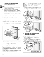
...shaft. The mark (a) attached at a height of the appliance until the mark (a) on the door. If there is used to the installation enclosure It is in alignment with the cabinet fronts using the feet at the front of 11/2" (32 mm) above the appliance, ensuring... positioning aid on the appliance. 2. Attaching the appliance to set perfectly levelled. Do not twist or jam the appliance inside the installation enclosure! When adjusting the heightadjustable feet, proceed gradually: Always alternate between left and right, etc. For easier adjustment of the rear...
...shaft. The mark (a) attached at a height of the appliance until the mark (a) on the door. If there is used to the installation enclosure It is in alignment with the cabinet fronts using the feet at the front of 11/2" (32 mm) above the appliance, ensuring... positioning aid on the appliance. 2. Attaching the appliance to set perfectly levelled. Do not twist or jam the appliance inside the installation enclosure! When adjusting the heightadjustable feet, proceed gradually: Always alternate between left and right, etc. For easier adjustment of the rear...
Installation Manual
Page 17
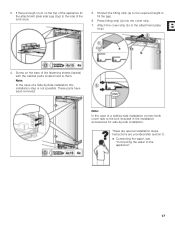
...These are provided after section C. Connecting the water, see "Connecting the water to the side of a side-by-side installation connect both cover rails to them. 3. Instructions are special installation steps. Note: In the case of the enclosure. 5. Attach the cover strip (b) to fill the gap. 6. Press fitting strip ...(a) into the cover strip. 7. If there enough room on the bars of a Side-by -side installation. Note: In the case of the fastening sheets (lateral) with the cabinet parts located next to the bolt included in the...
...These are provided after section C. Connecting the water, see "Connecting the water to the side of a side-by-side installation connect both cover rails to them. 3. Instructions are special installation steps. Note: In the case of the enclosure. 5. Attach the cover strip (b) to fill the gap. 6. Press fitting strip ...(a) into the cover strip. 7. If there enough room on the bars of a Side-by -side installation. Note: In the case of the fastening sheets (lateral) with the cabinet parts located next to the bolt included in the...
Installation Manual
Page 19
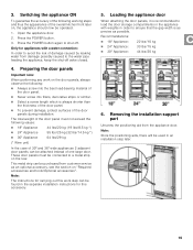
Press the POWER button. 3. This metal strip can be connected to shut off valve closed. 4. Removing the installation support part Unscrew the positioning aid from damage possibly caused to ensure that the gap width is as precise as an optional accessory, see the ... the water pipe feeding the appliance, keep the shut-off . Note: Store the positioning aids, there will be attached instead of the door panels during installation. Switching the appliance ON To guarantee the accuracy of the following : Always screw into the best load-bearing material of the door panel. ...
Press the POWER button. 3. This metal strip can be connected to shut off valve closed. 4. Removing the installation support part Unscrew the positioning aid from damage possibly caused to ensure that the gap width is as precise as an optional accessory, see the ... the water pipe feeding the appliance, keep the shut-off . Note: Store the positioning aids, there will be attached instead of the door panels during installation. Switching the appliance ON To guarantee the accuracy of the following : Always screw into the best load-bearing material of the door panel. ...
Installation Manual
Page 20
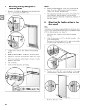
... tightly. 3. Attaching the fixation strips to the door panel 1. Determine and mark the centerline of the appliance door to the door panel with the next installation step ("C / 9. Use the height adjustment gauge (b). 2. Align the door panel with the double threaded bolts (Torx screwdriver). Mark this case continue with at least 10...
... tightly. 3. Attaching the fixation strips to the door panel 1. Determine and mark the centerline of the appliance door to the door panel with the next installation step ("C / 9. Use the height adjustment gauge (b). 2. Align the door panel with the double threaded bolts (Torx screwdriver). Mark this case continue with at least 10...
Installation Manual
Page 22
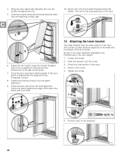
... of the door panel is aligned with the adjacent fronts. 4. Push the bracket over the fastening screws (2.). 10. Put the cover on the lower brackets (Installation kit). Screw in the door panel! 1. Adjust the door panel using the double threaded bolts (Torx screwdriver). Correct by gently tapping the edge of the...
... of the door panel is aligned with the adjacent fronts. 4. Push the bracket over the fastening screws (2.). 10. Put the cover on the lower brackets (Installation kit). Screw in the door panel! 1. Adjust the door panel using the double threaded bolts (Torx screwdriver). Correct by gently tapping the edge of the...
Installation Manual
Page 23
... = maximum spring tension 0 = no spring tension 2. The cover can be screwed to the door. Instructions are special installation steps. Installation of the appliance is included in the installation accessories for a wine unit, see "Attaching the cover strips" Door limitation pin, see "Adjusting the door ...is now complete. Insert the cover strip into the space between the appliances. Attaching the strips 1. 11. Side-by-Side installation only: These are provided after section C. Ice-water dispenser, see "Aligning the ice-water dispenser". Cover strips ...
... = maximum spring tension 0 = no spring tension 2. The cover can be screwed to the door. Instructions are special installation steps. Installation of the appliance is included in the installation accessories for a wine unit, see "Attaching the cover strips" Door limitation pin, see "Adjusting the door ...is now complete. Insert the cover strip into the space between the appliances. Attaching the strips 1. 11. Side-by-Side installation only: These are provided after section C. Ice-water dispenser, see "Aligning the ice-water dispenser". Cover strips ...
Installation Manual
Page 24
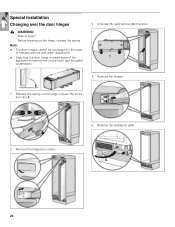
Unscrew (1.) and remove (2.) the door. 4. Release the spring on the hinge, release the spring. Remove the ventilation grille. 24 Loosen the screw from I to 0. 2. Remove the hinges. 1. Remove the hinge box covers. 5. Before working on the hinge. Note: The door hinges cannot be exchanged in the case of injury! Special installation Changing over the door hinges , WARNING: Risk of freezers with ice and water dispensers. Switching the door hinge is made easier if the appliance is stored here on the back (put the pallet underneath). 3.
Unscrew (1.) and remove (2.) the door. 4. Release the spring on the hinge, release the spring. Remove the ventilation grille. 24 Loosen the screw from I to 0. 2. Remove the hinges. 1. Remove the hinge box covers. 5. Before working on the hinge. Note: The door hinges cannot be exchanged in the case of injury! Special installation Changing over the door hinges , WARNING: Risk of freezers with ice and water dispensers. Switching the door hinge is made easier if the appliance is stored here on the back (put the pallet underneath). 3.
Installation Manual
Page 25
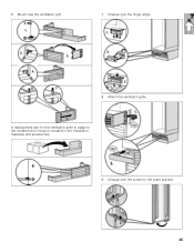
Change over the screw for the ventilation grille to adapt to the modified door hinge is included in the installation materials and accessories. 9. A replacement part for the lower bracket. 25 Change over the hinge angle. 8. Attach the ventilation grille. Mount new the ventilation grill. 7. 6.
Change over the screw for the ventilation grille to adapt to the modified door hinge is included in the installation materials and accessories. 9. A replacement part for the lower bracket. 25 Change over the hinge angle. 8. Attach the ventilation grille. Mount new the ventilation grill. 7. 6.
