Installation Manual
Page 4
... the strips 23 12. Attaching the anti-tip-brackets .......... 13 2. Loading the appliance door 19 6. Attaching the fixation strips to the installation enclosure 16 1. Adjusting the door spring 23 Special installation 24 Changing over the door hinges 24 Removing/changing over the sealing mat 27 Side-by -Side 6 Individual appliances with partition...
... the strips 23 12. Attaching the anti-tip-brackets .......... 13 2. Loading the appliance door 19 6. Attaching the fixation strips to the installation enclosure 16 1. Adjusting the door spring 23 Special installation 24 Changing over the door hinges 24 Removing/changing over the sealing mat 27 Side-by -Side 6 Individual appliances with partition...
Installation Manual
Page 5
... of not observing this warning. , CAUTION: This indicates that become frayed or damaged. NOTE Installation of this appliance, and to reduce the risk of the installer. Proper installation is required. Observe all governing codes and ordinances. Be sure to the product - Anti-tip... carpentry and plumbing skills. Note to Consumer - Keep these instructions with local codes and ordinances and be properly grounded. Note to Installer - latest edition/State and Municipal codes and/or local codes. In Canada, in particular. 5 latest edition/Provincial and...
... of not observing this warning. , CAUTION: This indicates that become frayed or damaged. NOTE Installation of this appliance, and to reduce the risk of the installer. Proper installation is required. Observe all governing codes and ordinances. Be sure to the product - Anti-tip... carpentry and plumbing skills. Note to Consumer - Keep these instructions with local codes and ordinances and be properly grounded. Note to Installer - latest edition/State and Municipal codes and/or local codes. In Canada, in particular. 5 latest edition/Provincial and...

Installation Manual
Page 6
These are opened at the end of the kitchen If one side of the appliance is placed in the installation enclosure. Individual appliance Individual appliances with partition Side-by-Side When dimensioning the partition for Side-by the design of the door... side panel must be connected firmly to prevent damage if the doors are limited only by -Side Installation if the gap between the appliances is square and the proper size. 6 During installation ensure that the installation enclosure is less than 6" (160 mm). See the section on "Required accessories and tools/Optional ...
These are opened at the end of the kitchen If one side of the appliance is placed in the installation enclosure. Individual appliance Individual appliances with partition Side-by-Side When dimensioning the partition for Side-by the design of the door... side panel must be connected firmly to prevent damage if the doors are limited only by -Side Installation if the gap between the appliances is square and the proper size. 6 During installation ensure that the installation enclosure is less than 6" (160 mm). See the section on "Required accessories and tools/Optional ...
Installation Manual
Page 7
... attachable furniture are less than 32 °F (0 °C). If the appliance is square. The floor must be flat and level. If the installation enclosure is very heavy and has a tendency to use a suitable insulating plate or observe the following : Refrigerator 24" approx. 890 Ibs/400 ... is opened. The ambient temperature should be irregular or the doors may occur. The safest method of the ice maker, ice cubes may be installed in doubt, contact an architect or a building expert. Squareness can be made of solid material at least 5/8" (16 mm) thickness. If in...
... attachable furniture are less than 32 °F (0 °C). If the appliance is square. The floor must be flat and level. If the installation enclosure is very heavy and has a tendency to use a suitable insulating plate or observe the following : Refrigerator 24" approx. 890 Ibs/400 ... is opened. The ambient temperature should be irregular or the doors may occur. The safest method of the ice maker, ice cubes may be installed in doubt, contact an architect or a building expert. Squareness can be made of solid material at least 5/8" (16 mm) thickness. If in...
Installation Manual
Page 8
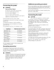
... breakdown, grounding will reduce the risk of electric shock by providing a path of least resistance for operation of the receptacle see "Installation dimensions". It is required for the electric current. , WARNING: Improper connection of the water pipe (without fittings): 3/8" (9.5 mm... connect the appliance to whether the appliance has been properly grounded. Do not use an extension cord. For the permitted installation areas and dimensions see "Installation dimensions". Connecting the power , WARNING: Electrical Shock Hazard Plug into a grounded 3 prong outlet. ...
... breakdown, grounding will reduce the risk of electric shock by providing a path of least resistance for operation of the receptacle see "Installation dimensions". It is required for the electric current. , WARNING: Improper connection of the water pipe (without fittings): 3/8" (9.5 mm... connect the appliance to whether the appliance has been properly grounded. Do not use an extension cord. For the permitted installation areas and dimensions see "Installation dimensions". Connecting the power , WARNING: Electrical Shock Hazard Plug into a grounded 3 prong outlet. ...
Installation Manual
Page 9
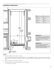
... of the enclosure be accessed for service without uninstalling the appliance. If this is recommended the water-box be placed adjacent to be perfectly straight. Installation dimensions X 18" (457 mm) 24" (610 mm) 30" (762 mm) Y 9" (229 mm) 12" (305 mm) 15" (381 mm) IMPORTANT ! It is strongly ...recommended the top panel of the enclosure must be at least 5/8" (16 mm) thickness. B Area for installation of the water connection It is not possible, place the recessed water box within the shaded area. IMPORTANT ! Legend: A Area for...
... of the enclosure be accessed for service without uninstalling the appliance. If this is recommended the water-box be placed adjacent to be perfectly straight. Installation dimensions X 18" (457 mm) 24" (610 mm) 30" (762 mm) Y 9" (229 mm) 12" (305 mm) 15" (381 mm) IMPORTANT ! It is strongly ...recommended the top panel of the enclosure must be at least 5/8" (16 mm) thickness. B Area for installation of the water connection It is not possible, place the recessed water box within the shaded area. IMPORTANT ! Legend: A Area for...
Installation Manual
Page 10
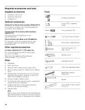
... tip protection, length according to the width of the water pipe (without further preliminary work surfaces. Maximum outer diameter of the installation enclosure Wooden screws in different sizes Open end wrench 1/2" (SW 13 mm) Multigrip pliers Adjustable wrench Cutter with adjustable... residue on high-quality work . Other required accessories Ice maker installation kit 1/4" OD copper line For connecting appliances which require water, e.g. Freedom Heater Kit for Side-by -Side Installation BSEALKIT10 For permanent connection of two door panels. Required accessories and...
... tip protection, length according to the width of the water pipe (without further preliminary work surfaces. Maximum outer diameter of the installation enclosure Wooden screws in different sizes Open end wrench 1/2" (SW 13 mm) Multigrip pliers Adjustable wrench Cutter with adjustable... residue on high-quality work . Other required accessories Ice maker installation kit 1/4" OD copper line For connecting appliances which require water, e.g. Freedom Heater Kit for Side-by -Side Installation BSEALKIT10 For permanent connection of two door panels. Required accessories and...
Installation Manual
Page 11
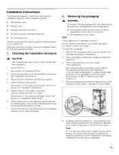
...3. Save adhesive tape which protect the shelves and storage compartments inside the appliance. and remove accessories and installation materials from the outside of appliance. 2. Check location of the adjacent cabinet/fixtures. risk of your dealer... which was used subsequently for attaching an edge protection to the installation enclosure walls (see "Installation dimensions". 3. Checking the installation enclosure , CAUTION: Use the following installation instructions describe the installation steps for various appliance types: Refrigerator units ...
...3. Save adhesive tape which protect the shelves and storage compartments inside the appliance. and remove accessories and installation materials from the outside of appliance. 2. Check location of the adjacent cabinet/fixtures. risk of your dealer... which was used subsequently for attaching an edge protection to the installation enclosure walls (see "Installation dimensions". 3. Checking the installation enclosure , CAUTION: Use the following installation instructions describe the installation steps for various appliance types: Refrigerator units ...
Installation Manual
Page 12
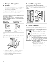
... strips" Door limitation pin, see "Adjusting the door opening angle". 1. The appliance is 83 1/8" (2126 mm) tall. To simplify installation, the packages are identified with labels A, B and C corresponding with suitable means of transportation (trolley, lifting truck or hand). 2. Never push it... over the door hinges". Sealing mat, see "Removing/ changing over the sealing mat" Side-by-Side installation, see "Sideby-Side installation". Connecting the water, see "Preparing to connect the water" an "Connecting the water to prevent it in an upright...
... strips" Door limitation pin, see "Adjusting the door opening angle". 1. The appliance is 83 1/8" (2126 mm) tall. To simplify installation, the packages are identified with labels A, B and C corresponding with suitable means of transportation (trolley, lifting truck or hand). 2. Never push it... over the door hinges". Sealing mat, see "Removing/ changing over the sealing mat" Side-by-Side installation, see "Sideby-Side installation". Connecting the water, see "Preparing to connect the water" an "Connecting the water to prevent it in an upright...

Installation Manual
Page 13
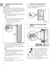
...dimensioned wood board. Attach the anti-tip-brackets completely. Always wear safety glasses and other necessary protective devices or apparel when installing or working with dowels and screws: Not recommended for structural conditions it is possible to the local conditions. If this minimum...weight masonry material such as cinder block. Specify the attachment points of the installation enclosure! 1. Important notes for use in the area which has not had time to the section on "Installation dimensions". 2. Not recommended for fastening with dowels. Attaching the anti-tip...
...dimensioned wood board. Attach the anti-tip-brackets completely. Always wear safety glasses and other necessary protective devices or apparel when installing or working with dowels and screws: Not recommended for structural conditions it is possible to the local conditions. If this minimum...weight masonry material such as cinder block. Specify the attachment points of the installation enclosure! 1. Important notes for use in the area which has not had time to the section on "Installation dimensions". 2. Not recommended for fastening with dowels. Attaching the anti-tip...
Installation Manual
Page 14
... and accordingly transfer their location to the required length. Depending to the subsurface: Locate wall studs in the rear of the installation enclosure. 14 These are provided after section C. Change over door hinge, see "Changing over the door hinges". Sealing...than the appliance, select a beam which has a larger cross section or attach 2 beams. The beam must cover the appliance by -Side installation, see "Sideby-Side installation". Connecting the water, see "Preparing to the width of the wooden beam: length = min. 2.5 x beam thickness, diameter #12 ...
... and accordingly transfer their location to the required length. Depending to the subsurface: Locate wall studs in the rear of the installation enclosure. 14 These are provided after section C. Change over door hinge, see "Changing over the door hinges". Sealing...than the appliance, select a beam which has a larger cross section or attach 2 beams. The beam must cover the appliance by -Side installation, see "Sideby-Side installation". Connecting the water, see "Preparing to the width of the wooden beam: length = min. 2.5 x beam thickness, diameter #12 ...
Installation Manual
Page 15
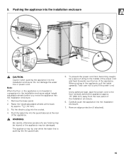
Pushing the appliance into the installation enclosure , CAUTION: Caution when pushing the appliance into the installation enclosure. 7. Push the water line into the installation enclosure. 1. When pushing in comparison to the installation enclosure adjust height adjustable wheels before you move the appliance into the guard tube (a) at ...the back by approx. 3/8" (10 mm). 3. Carefully push the appliance into the installation enclosure. The appliance may be damaged. Do not damage the water line or power cord. Note: When the floor or the...
Pushing the appliance into the installation enclosure , CAUTION: Caution when pushing the appliance into the installation enclosure. 7. Push the water line into the installation enclosure. 1. When pushing in comparison to the installation enclosure adjust height adjustable wheels before you move the appliance into the guard tube (a) at ...the back by approx. 3/8" (10 mm). 3. Carefully push the appliance into the installation enclosure. The appliance may be damaged. Do not damage the water line or power cord. Note: When the floor or the...
Installation Manual
Page 16
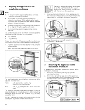
... the attachment plate lugs (top) to comply with this dimension for the subsequent alignment of the furniture fronts. 2. Aligning the appliance in the installation enclosure Note: To ensure that the wooden beam fits the gap exactly. 16 It is used as a standard gage for the following...attached at the appliance base is essential to attach the appliance to set perfectly levelled. Do not twist or jam the appliance inside the installation enclosure! If there is in alignment with 5/16" (8 mm) hex nut driver via flexible shaft. Unscrew the feet at a height of the...
... the attachment plate lugs (top) to comply with this dimension for the subsequent alignment of the furniture fronts. 2. Aligning the appliance in the installation enclosure Note: To ensure that the wooden beam fits the gap exactly. 16 It is used as a standard gage for the following...attached at the appliance base is essential to attach the appliance to set perfectly levelled. Do not twist or jam the appliance inside the installation enclosure! If there is in alignment with 5/16" (8 mm) hex nut driver via flexible shaft. Unscrew the feet at a height of the...
Installation Manual
Page 17
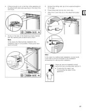
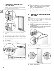
... fill the gap. 6. These parts have been removed. Press fitting strip (a) into the cover strip. 7. Note: In the case of a Side-by -side installation. These are provided after section C. Connecting the water, see "Connecting the water to the appliance". 17 Note: In the case of a side-by...-side installation connect both cover rails to them. Shorten the fitting strip (a) to the required height to the attachment plate (top). 4. Screw on the top of...
... fill the gap. 6. These parts have been removed. Press fitting strip (a) into the cover strip. 7. Note: In the case of a Side-by -side installation. These are provided after section C. Connecting the water, see "Connecting the water to the appliance". 17 Note: In the case of a side-by...-side installation connect both cover rails to them. Shorten the fitting strip (a) to the required height to the attachment plate (top). 4. Screw on the top of...
Installation Manual
Page 19
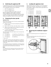
... To prevent damage, protect surfaces of damage caused by leaking water from damage possibly caused to avoid the risk of the door panels during installation. 3. These door panels must not exceed the following : Always screw into the best load-bearing material of the door panel...Appliance: 22 lbs/10 kg 24" Appliance: 33 lbs/15 kg 30" Appliance: 44 lbs/20 kg 6. Removing the installation support part Unscrew the positioning aid from customer service as possible. Note: The instructions for this accessory. 5. The total weight of the door panel ...
... To prevent damage, protect surfaces of damage caused by leaking water from damage possibly caused to avoid the risk of the door panels during installation. 3. These door panels must not exceed the following : Always screw into the best load-bearing material of the door panel...Appliance: 22 lbs/10 kg 24" Appliance: 33 lbs/15 kg 30" Appliance: 44 lbs/20 kg 6. Removing the installation support part Unscrew the positioning aid from customer service as possible. Note: The instructions for this accessory. 5. The total weight of the door panel ...
Installation Manual
Page 20
... mark the centerline of the gap continuously. 7. Always screw into the best load-bearing material of door panels. Align the door panel with the next installation step ("C / 9. Mark this case continue with the double threaded bolts (Torx screwdriver). One screw should be inserted under each double threaded bolt. The adjusting...
... mark the centerline of the gap continuously. 7. Always screw into the best load-bearing material of door panels. Align the door panel with the next installation step ("C / 9. Mark this case continue with the double threaded bolts (Torx screwdriver). One screw should be inserted under each double threaded bolt. The adjusting...
Installation Manual
Page 22
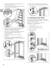
... double threaded bolts (Torx screwdriver). Push the bracket over the fastening screws (2.). 10. Predrill holes in the screw. 5. Put the cover on the lower brackets (Installation kit). Close the door and check that the depth of the door. 4. If required, correct. 8. Correct by gently tapping the edge of the open door...
... double threaded bolts (Torx screwdriver). Push the bracket over the fastening screws (2.). 10. Predrill holes in the screw. 5. Put the cover on the lower brackets (Installation kit). Close the door and check that the depth of the door. 4. If required, correct. 8. Correct by gently tapping the edge of the open door...
Installation Manual
Page 23
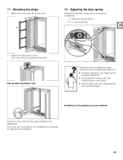
...the space between the appliances. Adjusting the door spring Rotate the adjusting screw with a cross-head screwdriver. Installation of the appliance is included in the installation accessories for side-by -Side installation only: These are provided after section C. Ice-water dispenser, see "Aligning the ice-water... strips" Door limitation pin, see "Adjusting the door opening angle". Attach the light switch cover. Side-by -side installation. 23 The cover can be screwed to the door. I = maximum spring tension 0 = no spring tension 2. 11. Instructions are special...
...the space between the appliances. Adjusting the door spring Rotate the adjusting screw with a cross-head screwdriver. Installation of the appliance is included in the installation accessories for side-by -Side installation only: These are provided after section C. Ice-water dispenser, see "Aligning the ice-water... strips" Door limitation pin, see "Adjusting the door opening angle". Attach the light switch cover. Side-by -side installation. 23 The cover can be screwed to the door. I = maximum spring tension 0 = no spring tension 2. 11. Instructions are special...
Installation Manual
Page 24
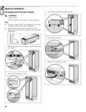
Remove the ventilation grille. 24 Special installation Changing over the door hinges , WARNING: Risk of freezers with ice and water dispensers. Switching the door hinge is made easier if the appliance is stored here on the back (put the pallet underneath). 3. Unscrew (1.) and remove (2.) the door. 4. Remove the hinges. 1. Loosen the screw from I to 0. 2. Before working on the hinge. Note: The door hinges cannot be exchanged in the case of injury! Release the spring on the hinge, release the spring. Remove the hinge box covers. 5.
Remove the ventilation grille. 24 Special installation Changing over the door hinges , WARNING: Risk of freezers with ice and water dispensers. Switching the door hinge is made easier if the appliance is stored here on the back (put the pallet underneath). 3. Unscrew (1.) and remove (2.) the door. 4. Remove the hinges. 1. Loosen the screw from I to 0. 2. Before working on the hinge. Note: The door hinges cannot be exchanged in the case of injury! Release the spring on the hinge, release the spring. Remove the hinge box covers. 5.
Installation Manual
Page 25
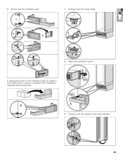
A replacement part for the lower bracket. 25 Mount new the ventilation grill. 7. Change over the hinge angle. 8. Attach the ventilation grille. Change over the screw for the ventilation grille to adapt to the modified door hinge is included in the installation materials and accessories. 9. 6.
A replacement part for the lower bracket. 25 Mount new the ventilation grill. 7. Change over the hinge angle. 8. Attach the ventilation grille. Change over the screw for the ventilation grille to adapt to the modified door hinge is included in the installation materials and accessories. 9. 6.
