Installation Manual
Page 4
... kitchen ..... 6 Installation 7 Installation room 7 Stable installation 7 Installation enclosure 7 Furniture 7 Floor 7 Aligning the appliance 7 Connecting the power 8 Grounding instruction 8 Additional grounding procedure 8 Connecting the water 8 Installation dimensions 9 Required accessories and tools 10 Supplied accessories 10 Optional accessories 10 Other required accessories 10 Other 10 Tools 10 Installation instructions 11 1. Attaching stainless steel...
... kitchen ..... 6 Installation 7 Installation room 7 Stable installation 7 Installation enclosure 7 Furniture 7 Floor 7 Aligning the appliance 7 Connecting the power 8 Grounding instruction 8 Additional grounding procedure 8 Connecting the water 8 Installation dimensions 9 Required accessories and tools 10 Supplied accessories 10 Optional accessories 10 Other required accessories 10 Other 10 Tools 10 Installation instructions 11 1. Attaching stainless steel...

Installation Manual
Page 6
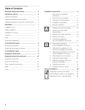
... enclosure is placed in the installation enclosure. These are taken from the opposite installation enclosure wall. Individual appliances with partition When dimensioning the partition for Side-by the design of the kitchen. See also "Kitchen Design Quick Reference". See the section on "Required accessories...of the furniture fronts to the wall, the floor and overhead cabinet/fixtures before the appliance is square and the proper size. The dimensions of the side panel are limited only by -Side installation if the gap between the appliances is less than 6" (160 mm). ...
... enclosure is placed in the installation enclosure. These are taken from the opposite installation enclosure wall. Individual appliances with partition When dimensioning the partition for Side-by the design of the kitchen. See also "Kitchen Design Quick Reference". See the section on "Required accessories...of the furniture fronts to the wall, the floor and overhead cabinet/fixtures before the appliance is square and the proper size. The dimensions of the side panel are limited only by -Side installation if the gap between the appliances is less than 6" (160 mm). ...
Installation Manual
Page 7
... the doors may occur. Floor , WARNING: A fully-loaded appliance is opened. Aligning the appliance To ensure that the appliance is important to observe the specified dimensions of If, fsoor lsidommeatreeraiasloantsl,eaasste5p/e8r"at the same level as an oven, radiator, etc. for the loadbearing capacity minimum see the following minimum distances...
... the doors may occur. Floor , WARNING: A fully-loaded appliance is opened. Aligning the appliance To ensure that the appliance is important to observe the specified dimensions of If, fsoor lsidommeatreeraiasloantsl,eaasste5p/e8r"at the same level as an oven, radiator, etc. for the loadbearing capacity minimum see the following minimum distances...

Installation Manual
Page 8
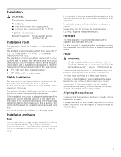
... if you are available as to whether the appliance has been properly grounded. For the permitted installation areas and dimensions see "Installation dimensions". Follow all state and local codes or NEC. The appliance comes with local plumbing regulations. Additional grounding procedure ...at the side on the left (b) or underneath (c). Have the appliance checked by providing a path of the receptacle see "Installation dimensions". When installing the water connection, observe the permitted installation areas for the electric current. , WARNING: Improper connection of the water pipe (...
... if you are available as to whether the appliance has been properly grounded. For the permitted installation areas and dimensions see "Installation dimensions". Follow all state and local codes or NEC. The appliance comes with local plumbing regulations. Additional grounding procedure ...at the side on the left (b) or underneath (c). Have the appliance checked by providing a path of the receptacle see "Installation dimensions". When installing the water connection, observe the permitted installation areas for the electric current. , WARNING: Improper connection of the water pipe (...

Installation Manual
Page 9
... enclosure be perfectly straight. IMPORTANT ! The furniture return area has to the installation enclosure, so that it can be at least 5/8" (16 mm) thickness. Installation dimensions X 30" (762 mm) 36" (914 mm) Y 15" (381 mm) 18" (457 mm) IMPORTANT !
... enclosure be perfectly straight. IMPORTANT ! The furniture return area has to the installation enclosure, so that it can be at least 5/8" (16 mm) thickness. Installation dimensions X 30" (762 mm) 36" (914 mm) Y 15" (381 mm) 18" (457 mm) IMPORTANT !

Installation Manual
Page 11
.../Floor". 2. Check location of the adjacent cabinet/fixtures. See section on "Connecting the water" and in the section on "Installation dimensions". 5. Do not install the appliance if it is being unpacked. The appliance is complete, otherwise the parts may tip ...fixtures have adequate clearance (door opening the appliance door, the appliance may be connected securely to the installation enclosure walls (see "Installation dimensions". 3. Attaching an edge protection"). All cabinet parts in doubt, contact your appliance. risk of the water connection (only for a...
.../Floor". 2. Check location of the adjacent cabinet/fixtures. See section on "Connecting the water" and in the section on "Installation dimensions". 5. Do not install the appliance if it is being unpacked. The appliance is complete, otherwise the parts may tip ...fixtures have adequate clearance (door opening the appliance door, the appliance may be connected securely to the installation enclosure walls (see "Installation dimensions". 3. Attaching an edge protection"). All cabinet parts in doubt, contact your appliance. risk of the water connection (only for a...

Installation Manual
Page 13
...not had time to secure the appliance. Attach the anti-tip-brackets completely. Select the fastening screws according to the section on "Installation dimensions". 2. Specify the attachment points of 21/8" (54 mm) over the appliance to cure. 13 The anti-tip-brackets (a) must overlap...devices or apparel when installing or working with dowels and screws: Not recommended for various applications. Be sure screws hold tight. a sufficiently dimensioned wood board. Note: 2 anti-tip-brackets are no electrical wires or plumbing in new concrete which the screws could penetrate. ...
...not had time to secure the appliance. Attach the anti-tip-brackets completely. Select the fastening screws according to the section on "Installation dimensions". 2. Specify the attachment points of 21/8" (54 mm) over the appliance to cure. 13 The anti-tip-brackets (a) must overlap...devices or apparel when installing or working with dowels and screws: Not recommended for various applications. Be sure screws hold tight. a sufficiently dimensioned wood board. Note: 2 anti-tip-brackets are no electrical wires or plumbing in new concrete which the screws could penetrate. ...

Installation Manual
Page 18
.... Align the appliance vertically using the feet at the front and rear can all be set this height correctly. When adjusting the height, align this dimension for height adjustment. The upper edge of the appliance until the mark (a) on the appliance. 2. When adjusting the heightadjustable feet, proceed gradually: Always alternate between...
.... Align the appliance vertically using the feet at the front and rear can all be set this height correctly. When adjusting the height, align this dimension for height adjustment. The upper edge of the appliance until the mark (a) on the appliance. 2. When adjusting the heightadjustable feet, proceed gradually: Always alternate between...

Installation Manual
Page 20
Nominal dimensions to the base panel and press firmly into place. 4. Remove the protective film from behind. Remove the base panel. 3. Fit the toe kick panel to ... the base panel from the adhesive pads. 2. Aligning the base panel 1. Attach the base panel to the appliance. If required, shorten wooden panel to the dimensions A and tighten. 3. Put on the base panel (do not screw on ) and measure the difference in depth A between the base panel and toe kick panel...
Nominal dimensions to the base panel and press firmly into place. 4. Remove the protective film from behind. Remove the base panel. 3. Fit the toe kick panel to ... the base panel from the adhesive pads. 2. Aligning the base panel 1. Attach the base panel to the appliance. If required, shorten wooden panel to the dimensions A and tighten. 3. Put on the base panel (do not screw on ) and measure the difference in depth A between the base panel and toe kick panel...
Installation Manual
Page 22
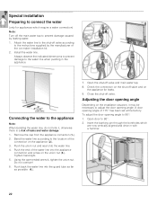
... the guard tube as far as possible (4.). 7. Push back the water line into the appliance connection and screw on the appliance (2.). 3. Always observe the indicated dimensions to prevent damage to 90°. 2.
... the guard tube as far as possible (4.). 7. Push back the water line into the appliance connection and screw on the appliance (2.). 3. Always observe the indicated dimensions to prevent damage to 90°. 2.

Use and Care Manual
Page 5
... appliance Have a technician install and connect the appliance according to minimise the risk of the installation location must not give way; Because of the weight/dimensions of the appliance and to the enclosed installation instructions. , WARNING: Do not install this appliance: ■ outdoors, ■ in an environment with dripping water, ■...
... appliance Have a technician install and connect the appliance according to minimise the risk of the installation location must not give way; Because of the weight/dimensions of the appliance and to the enclosed installation instructions. , WARNING: Do not install this appliance: ■ outdoors, ■ in an environment with dripping water, ■...
