Product Brochure (Accessory Chart for XC Cameras)
Page 1
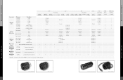
...for S 12 used when IR cut filter is removed XC-EI30 XC-EI30CE B/W 1/3 type CCD XC-ES30 XC-ES30CE XC-ST30 XC-ST30CE XC-55 XC-55BB/1 Color XC-777A XC-777AP XC-003 XC-003P B/W 1/2 type CCD XC-7500 XC-EI50 XC-ES50 XC-HR300 XC-ST50 XC-8500CE XC-EI50CE XC-ES50CE XC-ST50CE Color XC-999 XC-999P B/W 2/3 type CCD XC-ST70 XC-ST70CE 32.6˚x24.8˚ 22.4˚x16.9˚ ...-999CMT in case of a C-mount lens for NF mount type FILTER IR CUT LO-37IR FILTER ND 64 NEUTRAL LO-37ND Accessories for XC series Accessories for XC series VCL-03S12XM VCL-08YM 50mm Macro Lens VCL-7S12XEA
...for S 12 used when IR cut filter is removed XC-EI30 XC-EI30CE B/W 1/3 type CCD XC-ES30 XC-ES30CE XC-ST30 XC-ST30CE XC-55 XC-55BB/1 Color XC-777A XC-777AP XC-003 XC-003P B/W 1/2 type CCD XC-7500 XC-EI50 XC-ES50 XC-HR300 XC-ST50 XC-8500CE XC-EI50CE XC-ES50CE XC-ST50CE Color XC-999 XC-999P B/W 2/3 type CCD XC-ST70 XC-ST70CE 32.6˚x24.8˚ 22.4˚x16.9˚ ...-999CMT in case of a C-mount lens for NF mount type FILTER IR CUT LO-37IR FILTER ND 64 NEUTRAL LO-37ND Accessories for XC series Accessories for XC series VCL-03S12XM VCL-08YM 50mm Macro Lens VCL-7S12XEA

Accessory Chart (ip_ac_01)
Page 1
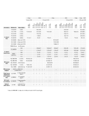
... Color 1/4-inch CCD 1/3-inch CCD 1/2-inch CCD 2/3-inch CCD XC-55 XC-55BB XC-73 / XC-73CE XC-EI30 / XC-EI30CE XC-ES30 / XC-ES30CE XC-ST30 / XC-ST30CE XC-7500 / XC-8500CE XC-75 / XC-75CE XC-EI50 / XC-EI50CE XC-ES50 / XC-ES50CE XC-ST50 / XC-ST50CE XC-ST70 / XC-ST70CE XCH-1125 XC-333 / XC-333P XC-003 / XC-003P XC-777A / XC-777AP XC-999 / XC-999P XC-711 / XC-711P Accessory Reference Description CCXC-H12P05 XCH to JB...
... Color 1/4-inch CCD 1/3-inch CCD 1/2-inch CCD 2/3-inch CCD XC-55 XC-55BB XC-73 / XC-73CE XC-EI30 / XC-EI30CE XC-ES30 / XC-ES30CE XC-ST30 / XC-ST30CE XC-7500 / XC-8500CE XC-75 / XC-75CE XC-EI50 / XC-EI50CE XC-ES50 / XC-ES50CE XC-ST50 / XC-ST50CE XC-ST70 / XC-ST70CE XCH-1125 XC-333 / XC-333P XC-003 / XC-003P XC-777A / XC-777AP XC-999 / XC-999P XC-711 / XC-711P Accessory Reference Description CCXC-H12P05 XCH to JB...
Accessory Chart (ip_ac_01)
Page 2
... B/W 1/3-inch CCD Color B/W 1/2-inch CCD Color Color B/W 2/3-inch CCD XC-333 XC-333P XC-73 XC-73CE XC-EI30 XC-EI30CE XC-ES30 XC-ES30CE XC-ST30 XC-ST30CE XC-55 XC-55BB XC-777A XC-777AP XC-003 XC-003P XC-7500 XC-8500CE XC-75 XC-75CE XC-EI50 XC-EI50CE XC-ES50 XC-ES50CE XC-ST50 XC-ST50CE XC-999 XC-999P XC-711 XC-711P XC-ST70 XC-ST70CE Accessory Reference Description VCL-08YM f=8mm VCL-12YM f=12mm *17...
... B/W 1/3-inch CCD Color B/W 1/2-inch CCD Color Color B/W 2/3-inch CCD XC-333 XC-333P XC-73 XC-73CE XC-EI30 XC-EI30CE XC-ES30 XC-ES30CE XC-ST30 XC-ST30CE XC-55 XC-55BB XC-777A XC-777AP XC-003 XC-003P XC-7500 XC-8500CE XC-75 XC-75CE XC-EI50 XC-EI50CE XC-ES50 XC-ES50CE XC-ST50 XC-ST50CE XC-999 XC-999P XC-711 XC-711P XC-ST70 XC-ST70CE Accessory Reference Description VCL-08YM f=8mm VCL-12YM f=12mm *17...
Product Manual (Black & White Analog Camera)
Page 1
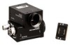
... external synchronization. For the customers in einem Industriegebiet bestimmt. Clean the exterior with 768 × 494 pixels (XC-ST70/ST50/ST30) or 752 × 582 pixels (XC-ST70CE/ST50CE/ ST30CE). For details on the camera adaptor DC-700/700CE, see "About the User's Guide" on... a trigger pulse and a WEN signal. 3-867-357-04 (1) CCD Black-and-White Video Camera Module Operating Instructions XC-ST70/ ST70CE XC-ST50/ ST50CE XC-ST30/ ST30CE Sony Corporation 1999 Printed in operation. Heat radiation Do not wrap the camera in cloth or other optical equipment. ...
... external synchronization. For the customers in einem Industriegebiet bestimmt. Clean the exterior with 768 × 494 pixels (XC-ST70/ST50/ST30) or 752 × 582 pixels (XC-ST70CE/ST50CE/ ST30CE). For details on the camera adaptor DC-700/700CE, see "About the User's Guide" on... a trigger pulse and a WEN signal. 3-867-357-04 (1) CCD Black-and-White Video Camera Module Operating Instructions XC-ST70/ ST70CE XC-ST50/ ST50CE XC-ST30/ ST30CE Sony Corporation 1999 Printed in operation. Heat radiation Do not wrap the camera in cloth or other optical equipment. ...
Product Manual (Black & White Analog Camera)
Page 2
...CCD imaging element uses an interline transfer system. A malfunctioning sensor element will cause a single pixel blemish in Figure F-c. XC-ST70CE/ST50CE/ST30CE: 1/4 to M (Manual). 9 Shutter speed/Mode setting DIP switch See Fig. WEN output (Signal) Trigger...XC-ST70CE/ST50CE/ST30CE: 14.1875 MHz Signal system XC-ST70/ST50/ST30: EIA system XC-ST70CE/ST50CE/ST30CE: CCIR system Cell size (horizontal/vertical) XC-ST70: 11.6 × 13.5 µm XC-ST70CE: 11.6 × 11.2 µm XC-ST50: 8.4 × 9.8 µm XC-ST50CE: 8.6 × 8.3 µm XC-ST30: 6.35 × 7.40 µm XC...
...CCD imaging element uses an interline transfer system. A malfunctioning sensor element will cause a single pixel blemish in Figure F-c. XC-ST70CE/ST50CE/ST30CE: 1/4 to M (Manual). 9 Shutter speed/Mode setting DIP switch See Fig. WEN output (Signal) Trigger...XC-ST70CE/ST50CE/ST30CE: 14.1875 MHz Signal system XC-ST70/ST50/ST30: EIA system XC-ST70CE/ST50CE/ST30CE: CCIR system Cell size (horizontal/vertical) XC-ST70: 11.6 × 13.5 µm XC-ST70CE: 11.6 × 11.2 µm XC-ST50: 8.4 × 9.8 µm XC-ST50CE: 8.6 × 8.3 µm XC-ST30: 6.35 × 7.40 µm XC...
User Manual (xcst70_User_Guide)
Page 3
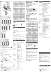
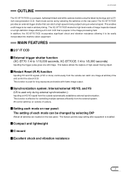
...rear panel. This feature allows the capture of each mode can be easily incorporated into machine vision equipment. In addition, the XC-ST70/70CE incorporates significant shock and vibration resistance allowing it to 1/8,000 seconds) Inputting the trigger pulse gives one image at ...external synchronization.) Inputting an HD/VD signal from the external system. MAIN FEATURES 2/3" IT CCD External trigger shutter function (XC-ST70: 1/4 to 1/10,000 seconds, XC-ST70CE: 1/4 to be set by selecting DIP Almost all switches are located on rear panel: The setting of high-speed...
...rear panel. This feature allows the capture of each mode can be easily incorporated into machine vision equipment. In addition, the XC-ST70/70CE incorporates significant shock and vibration resistance allowing it to 1/8,000 seconds) Inputting the trigger pulse gives one image at ...external synchronization.) Inputting an HD/VD signal from the external system. MAIN FEATURES 2/3" IT CCD External trigger shutter function (XC-ST70: 1/4 to 1/10,000 seconds, XC-ST70CE: 1/4 to be set by selecting DIP Almost all switches are located on rear panel: The setting of high-speed...
User Manual (xcst70_User_Guide)
Page 5
... pixels XC-ST70: 768(H) x 494(V) XC-ST70CE: 752(H) x 582(V) CCD horizontal driving frequency XC-ST70: 14.318 MHz XC-ST70CE: 14.187 MHz CCD vertical driving frequency XC-ST70: 15.734 kHz XC-ST70CE: 15.625 kHz Signal system EIA/CCIR Cell size XC-ST70: 11.6(H) x 13.5(V) um XC-ST70CE: 11...Scanning system 2:1 interlacing Non-interlacing (during external sync input) Horizontal resolution XC-ST70: 570 TV lines XC-ST70CE: 560 TV lines Sensitivity 400 lx F8 (γ = ON, 0 dB) S/N ratio XC-ST70: 60 dB XC-ST70CE: 58 dB Minimum subject illuminance 0.3 lx (F1.4, AGC ON) Gain...
... pixels XC-ST70: 768(H) x 494(V) XC-ST70CE: 752(H) x 582(V) CCD horizontal driving frequency XC-ST70: 14.318 MHz XC-ST70CE: 14.187 MHz CCD vertical driving frequency XC-ST70: 15.734 kHz XC-ST70CE: 15.625 kHz Signal system EIA/CCIR Cell size XC-ST70: 11.6(H) x 13.5(V) um XC-ST70CE: 11...Scanning system 2:1 interlacing Non-interlacing (during external sync input) Horizontal resolution XC-ST70: 570 TV lines XC-ST70CE: 560 TV lines Sensitivity 400 lx F8 (γ = ON, 0 dB) S/N ratio XC-ST70: 60 dB XC-ST70CE: 58 dB Minimum subject illuminance 0.3 lx (F1.4, AGC ON) Gain...
User Manual (xcst70_User_Guide)
Page 8
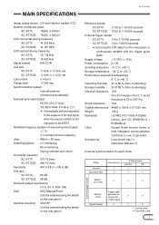
Unit: Clock 1 CLK = 69.84 n sec (XC-ST70) = 70.48 n sec (XC-ST70CE) Note : The synchronized VD signals are delayed for each mode • For normal video/normal shutter Continuous HD/VD signal (should be set as specified ... EXTERNAL SYNCHRONIZATION External synchronization for 1H at HD/VD external synchronization mode, while there is as shown below in the figure below with respect to XC-ST70CE. EXT-VD ODD (EVEN) EVEN (ODD) 100 200 5 200 EXT-HD 455 (454) 455 (454) The operation in the figure below.) • For Restart Reset...
Unit: Clock 1 CLK = 69.84 n sec (XC-ST70) = 70.48 n sec (XC-ST70CE) Note : The synchronized VD signals are delayed for each mode • For normal video/normal shutter Continuous HD/VD signal (should be set as specified ... EXTERNAL SYNCHRONIZATION External synchronization for 1H at HD/VD external synchronization mode, while there is as shown below in the figure below with respect to XC-ST70CE. EXT-VD ODD (EVEN) EVEN (ODD) 100 200 5 200 EXT-HD 455 (454) 455 (454) The operation in the figure below.) • For Restart Reset...
User Manual (xcst70_User_Guide)
Page 10
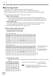
... 5 6 7 8 Mode 1 Mode 2 (Non-reset mode) (Reset mode) 0 0 0 0 0 0 0 0 Frame: 0 / Field: 1 0 0 1 0 1 1 Exposure time = Trigger pulse width + 97 µsec (XC-ST70) 120 µsec (XC-ST70CE) Note : 1. XC-ST70/70CE ELECTRONIC SHUTTER External trigger shutter These modes are used to set the shutter speed. • Using DIP switch on the rear...signal when an external HD/VD signal is input. • A video signal is synchronized with odd field for XC-ST70 and even field for XC-ST70CE. * For more , the output signal is input, a new trigger pulse must not be input before the ...
... 5 6 7 8 Mode 1 Mode 2 (Non-reset mode) (Reset mode) 0 0 0 0 0 0 0 0 Frame: 0 / Field: 1 0 0 1 0 1 1 Exposure time = Trigger pulse width + 97 µsec (XC-ST70) 120 µsec (XC-ST70CE) Note : 1. XC-ST70/70CE ELECTRONIC SHUTTER External trigger shutter These modes are used to set the shutter speed. • Using DIP switch on the rear...signal when an external HD/VD signal is input. • A video signal is synchronized with odd field for XC-ST70 and even field for XC-ST70CE. * For more , the output signal is input, a new trigger pulse must not be input before the ...

User Manual (xcst70_User_Guide)
Page 11
ELECTRONIC SHUTTER XC-ST70/70CE Specifications of trigger pulse When using a trigger pulse like shown below, set the TRIG polarity selector switch on the rear panel to + : A B T A: 2 to 5.0 V B: 0 ...: 10 kΩ or more * The voltage and pulse width used are measured at pin 11 of WEN (Write ENable Pulse) A B T A: 5.0 V B: 0 V T: 15.875 ms (XC-ST70), 18.752 ms (XC-ST70CE) * Output impedance: 10 kΩ or more 9 Specifications of a 12-pin multi-connector on the rear panel to - : A B T A: 4.0 to 5.0 V B: 0 to 2.0 V T: 2 µs to 1/4 s, 100 µ...
ELECTRONIC SHUTTER XC-ST70/70CE Specifications of trigger pulse When using a trigger pulse like shown below, set the TRIG polarity selector switch on the rear panel to + : A B T A: 2 to 5.0 V B: 0 ...: 10 kΩ or more * The voltage and pulse width used are measured at pin 11 of WEN (Write ENable Pulse) A B T A: 5.0 V B: 0 V T: 15.875 ms (XC-ST70), 18.752 ms (XC-ST70CE) * Output impedance: 10 kΩ or more 9 Specifications of a 12-pin multi-connector on the rear panel to - : A B T A: 4.0 to 5.0 V B: 0 to 2.0 V T: 2 µs to 1/4 s, 100 µ...
User Manual (xcst70_User_Guide)
Page 12
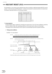
...Odd and even fields are required. XC-ST70/70CE RESTART RESET (R.R) The information on the rear panel of a camera as follows. • Timing and conditions Example 1 of Long exposure EXT HD Continuous signal: 15.734 kHz (XC-ST70), 15.625 kHz (XC-ST70CE) Allowable frequency value ±1% EXT... VD VD interval(T): 262.5H or more (XC-ST70), 312.5H or more (XC-ST70CE) and less than 1 second (Recommended) Four or more VD pulses are ...
...Odd and even fields are required. XC-ST70/70CE RESTART RESET (R.R) The information on the rear panel of a camera as follows. • Timing and conditions Example 1 of Long exposure EXT HD Continuous signal: 15.734 kHz (XC-ST70), 15.625 kHz (XC-ST70CE) Allowable frequency value ±1% EXT... VD VD interval(T): 262.5H or more (XC-ST70), 312.5H or more (XC-ST70CE) and less than 1 second (Recommended) Four or more VD pulses are ...

User Manual (xcst70_User_Guide)
Page 13
RESTART RESET (R.R) Example 2 of the EXT HD/VD signal input from the outside. 11 T 1/60 second 1/60 second Exposure time for Odd field Exposure time for Even field Video output Invalid image Odd image Even image Valid frame image Odd and even fields are determined by the phase of long exposure EXT HD Continuous signal: 15.734 kHz (XC-ST70), 15.625 kHz (XC-ST70CE) Allowable frequency value ±1% XC-ST70/70CE EXT VD VD interval(T): 262.5H or more (XC-ST70), 312.5H or more (XC-ST70CE) and less than 1 second (Recommended) Four or more VD pulses are required.
RESTART RESET (R.R) Example 2 of the EXT HD/VD signal input from the outside. 11 T 1/60 second 1/60 second Exposure time for Odd field Exposure time for Even field Video output Invalid image Odd image Even image Valid frame image Odd and even fields are determined by the phase of long exposure EXT HD Continuous signal: 15.734 kHz (XC-ST70), 15.625 kHz (XC-ST70CE) Allowable frequency value ±1% XC-ST70/70CE EXT VD VD interval(T): 262.5H or more (XC-ST70), 312.5H or more (XC-ST70CE) and less than 1 second (Recommended) Four or more VD pulses are required.

User Manual (xcst70_User_Guide)
Page 14
...the strobe when the exposure time of the two fields overlap. • Timing and conditions EXT HD Continuous signal: 15.734 kHz (XC-ST70), 15.625 kHz (XC-ST70CE) Allowable frequency value ±1% EXT VD Four or more VD pulses are required. Avoid lighting the scene during the light-emitting inhibit..., it is recommended not to flash between VD and VD + 10H (XC-ST70)/ 16H (XC-ST70CE). 12 XC-ST70/70CE FRAME IMAGE OUTPUT WITH STROBE LIGHT A full frame image with vertical resolution of 485 lines (XC-ST70) or 575 lines (XC-ST70CE) can be obtained with a strobe light by the phase of the EXT...
...the strobe when the exposure time of the two fields overlap. • Timing and conditions EXT HD Continuous signal: 15.734 kHz (XC-ST70), 15.625 kHz (XC-ST70CE) Allowable frequency value ±1% EXT VD Four or more VD pulses are required. Avoid lighting the scene during the light-emitting inhibit..., it is recommended not to flash between VD and VD + 10H (XC-ST70)/ 16H (XC-ST70CE). 12 XC-ST70/70CE FRAME IMAGE OUTPUT WITH STROBE LIGHT A full frame image with vertical resolution of 485 lines (XC-ST70) or 575 lines (XC-ST70CE) can be obtained with a strobe light by the phase of the EXT...

User Manual (xcst70_User_Guide)
Page 17
....5 ns Camera video output signal (Typical value) Dummy pixel Optical black portion Horizontal transfer stop period Optical black portion Horizontal blanking period (12.1 µs) XC-ST70/70CE • XC-ST70CE (CCIR) 736 Effective total pixel 752 Output video period 21 HSYNC (1.48 µs) 70 (4.93 µs) 81 (5.71 µs) 736 (51.9 µs) One...
....5 ns Camera video output signal (Typical value) Dummy pixel Optical black portion Horizontal transfer stop period Optical black portion Horizontal blanking period (12.1 µs) XC-ST70/70CE • XC-ST70CE (CCIR) 736 Effective total pixel 752 Output video period 21 HSYNC (1.48 µs) 70 (4.93 µs) 81 (5.71 µs) 736 (51.9 µs) One...

User Manual (xcst70_User_Guide)
Page 18
XC-ST70/70CE EOLUETCPTURTOWNAICVESFHOURTMTETRIMING CHART • XC-ST70CE (CCIR) Timing chart of vertical output waveform (2:1 interlaced field integration) 581+582 579+580 7+8 5+6 3+4 1+2 582 580+581 578+579 8+9 6+7 4+5 2+3 1 VD CCD output signal Camera video output signal Odd field (312.5 H) 7.5 H 305 H Even field (312.5 H) 7.5 H 305 H 1 14 6 3.5 Empty transfer Optical black portion 287.5 1 14 6 3 Empty transfer Optical black portion 287.5 Vertical blanking period (25 H) Vertical blanking period (25 H) 16
XC-ST70/70CE EOLUETCPTURTOWNAICVESFHOURTMTETRIMING CHART • XC-ST70CE (CCIR) Timing chart of vertical output waveform (2:1 interlaced field integration) 581+582 579+580 7+8 5+6 3+4 1+2 582 580+581 578+579 8+9 6+7 4+5 2+3 1 VD CCD output signal Camera video output signal Odd field (312.5 H) 7.5 H 305 H Even field (312.5 H) 7.5 H 305 H 1 14 6 3.5 Empty transfer Optical black portion 287.5 1 14 6 3 Empty transfer Optical black portion 287.5 Vertical blanking period (25 H) Vertical blanking period (25 H) 16

User Manual (xcst70_User_Guide)
Page 19
In this case. *2: Exposure time Te Te = Trigger width + 97 µs (XC-ST70), Te = Trigger width + 120 µs (XC-ST70CE) (The trigger width should be between 65 µs before the previous image is a signal input from the outside. During the trigger inhibit period, an ...is between 2 µs and 1/4 s) *3: The normal operation state is engaged when the trigger high period exceeds 1/3sec. The external trigger shutter operation is output. XC-ST70/70CE TIMING CHART OF EXTERNAL TRIGGER SHUTTER - Be sure to input both HD and VD signals in the output. MODE 1 (NON-RESET MODE) For...
In this case. *2: Exposure time Te Te = Trigger width + 97 µs (XC-ST70), Te = Trigger width + 120 µs (XC-ST70CE) (The trigger width should be between 65 µs before the previous image is a signal input from the outside. During the trigger inhibit period, an ...is between 2 µs and 1/4 s) *3: The normal operation state is engaged when the trigger high period exceeds 1/3sec. The external trigger shutter operation is output. XC-ST70/70CE TIMING CHART OF EXTERNAL TRIGGER SHUTTER - Be sure to input both HD and VD signals in the output. MODE 1 (NON-RESET MODE) For...

User Manual (xcst70_User_Guide)
Page 20
...the falling edge of the HD signal during input operation. *2: Exposure time Te Te = Trigger width + 97 µs (XC-ST70), Te = Trigger width + 120 µs (XC-ST70CE) (The trigger width should be between the falling edge of a trigger pulse (as shown by 1 and 2 in the ...area External trigger (50 ms) shutter operation 2 *2 Exposure time Te min 10 µs Video out WEN 1 *5 250H (XC-ST70) 293H (XC-ST70CE) 250H (XC-ST70) 293H (XC-ST70CE) 2 250H (XC-ST70) 293H (XC-ST70CE) *1: This is a signal input from the falling edge of a trigger pulse and the subsequent 50 ms period is output. ...
...the falling edge of the HD signal during input operation. *2: Exposure time Te Te = Trigger width + 97 µs (XC-ST70), Te = Trigger width + 120 µs (XC-ST70CE) (The trigger width should be between the falling edge of a trigger pulse (as shown by 1 and 2 in the ...area External trigger (50 ms) shutter operation 2 *2 Exposure time Te min 10 µs Video out WEN 1 *5 250H (XC-ST70) 293H (XC-ST70CE) 250H (XC-ST70) 293H (XC-ST70CE) 2 250H (XC-ST70) 293H (XC-ST70CE) *1: This is a signal input from the falling edge of a trigger pulse and the subsequent 50 ms period is output. ...

User Manual (xcst70_User_Guide)
Page 21
...10 µs 3 *1: This is a signal input from the outside. *2: Exposure time Te Te = Trigger width + 97 µs (XC-ST70), Te = Trigger width + 120 µs (XC-ST70CE) *3: The normal operation state is output. 19 MODE 1 (NON-RESET MODE) For setting the shutter speed using TRG width No HD/VD... 2 *2 Exposure time Te *2 Exposure time Te *4 Interrnal VD *5 T : T = 10 µs or more Video out 1 2 WEN 250H (XC-ST70) 293H (XC-ST70CE) *3 Normal operation 1/3 s or more details, refer to INT. *5: During external trigger shutter operation, an image is output when the next internal VD signal...
...10 µs 3 *1: This is a signal input from the outside. *2: Exposure time Te Te = Trigger width + 97 µs (XC-ST70), Te = Trigger width + 120 µs (XC-ST70CE) *3: The normal operation state is output. 19 MODE 1 (NON-RESET MODE) For setting the shutter speed using TRG width No HD/VD... 2 *2 Exposure time Te *2 Exposure time Te *4 Interrnal VD *5 T : T = 10 µs or more Video out 1 2 WEN 250H (XC-ST70) 293H (XC-ST70CE) *3 Normal operation 1/3 s or more details, refer to INT. *5: During external trigger shutter operation, an image is output when the next internal VD signal...

User Manual (xcst70_User_Guide)
Page 22
... when the next exposure ends before the previous image is output when an external VD signal falls 10 ms or more 3 WEN 250H (XC-ST70) 293H (XC-ST70CE) 250H (XC-ST70) 293H (XC-ST70CE) *1: This is an external input inhibition area. During the trigger inhibit period, an input trigger may be missed. *4: An image is output...
... when the next exposure ends before the previous image is output when an external VD signal falls 10 ms or more 3 WEN 250H (XC-ST70) 293H (XC-ST70CE) 250H (XC-ST70) 293H (XC-ST70CE) *1: This is an external input inhibition area. During the trigger inhibit period, an input trigger may be missed. *4: An image is output...

User Manual (xcst70_User_Guide)
Page 23
...state External input inhibition area External trigger (50 ms) shutter operation 2 *2 Exposure time Te min. 10 ms Video out WEN 1 250H (XC-ST70) 293H (XC-ST70CE) 2 250H (XC-ST70) 293H (XC-ST70CE) *1: This is a signal input from the rising edge of a trigger pulse (as shown by the setting of a trigger pulse and ...described above, the operation cannot be missed. *4: Be sure to input an external VD signal for 10 ms to 110 ms from the outside. XC-ST70/70CE TIMING CHART OF EXTERNAL TRIGGER SHUTTER - MODE 1 (NON-RESET MODE) For setting the shutter speed using DIP switch HD/VD input ...
...state External input inhibition area External trigger (50 ms) shutter operation 2 *2 Exposure time Te min. 10 ms Video out WEN 1 250H (XC-ST70) 293H (XC-ST70CE) 2 250H (XC-ST70) 293H (XC-ST70CE) *1: This is a signal input from the rising edge of a trigger pulse (as shown by the setting of a trigger pulse and ...described above, the operation cannot be missed. *4: Be sure to input an external VD signal for 10 ms to 110 ms from the outside. XC-ST70/70CE TIMING CHART OF EXTERNAL TRIGGER SHUTTER - MODE 1 (NON-RESET MODE) For setting the shutter speed using DIP switch HD/VD input ...
