
Operating Instructions
Page 4
...describe the controls on the upper left portion of the rear panel (see the illustration below). 4-XXX-XXX-XX(X) AA Area code SPEAKERS FRONT R FRONT L SUR R SUR L SUBWOOFER CENTER Any differences in operation, according to the area code, are clearly indicated in...DTS, Inc. © 1996-2008 DTS, Inc. "S-AIR" and its logo are trademarks of Sony Corporation. 4US This receiver incorporates High-Definition Multimedia Interface (HDMITM) technology. On Copyrights This receiver incorporates Dolby* Digital and Pro Logic Surround and the DTS** Digital Surround System. * Manufactured under ...
...describe the controls on the upper left portion of the rear panel (see the illustration below). 4-XXX-XXX-XX(X) AA Area code SPEAKERS FRONT R FRONT L SUR R SUR L SUBWOOFER CENTER Any differences in operation, according to the area code, are clearly indicated in...DTS, Inc. © 1996-2008 DTS, Inc. "S-AIR" and its logo are trademarks of Sony Corporation. 4US This receiver incorporates High-Definition Multimedia Interface (HDMITM) technology. On Copyrights This receiver incorporates Dolby* Digital and Pro Logic Surround and the DTS** Digital Surround System. * Manufactured under ...

Operating Instructions
Page 5
...6 Description and location of parts 8 Getting Started 1: Installing the speakers 15 2: Connecting the speakers 18 3: Connecting the TV 19 4: Connecting the audio/video components 20 5: Connecting the antennas 24 6: Preparing the receiver 24 7: Calibrating the appropriate settings automatically (AUTO CALIBRATION 25 Playback Selecting...components with one-touch operation (One-Touch Play 41 Enjoying the TV sound from the speakers connected to the receiver (System Audio Control 41 Turning off the receiver with the TV (System Power Off 43 Using the power saving function (HDMI Pass Through...
...6 Description and location of parts 8 Getting Started 1: Installing the speakers 15 2: Connecting the speakers 18 3: Connecting the TV 19 4: Connecting the audio/video components 20 5: Connecting the antennas 24 6: Preparing the receiver 24 7: Calibrating the appropriate settings automatically (AUTO CALIBRATION 25 Playback Selecting...components with one-touch operation (One-Touch Play 41 Enjoying the TV sound from the speakers connected to the receiver (System Audio Control 41 Turning off the receiver with the TV (System Power Off 43 Using the power saving function (HDMI Pass Through...

Operating Instructions
Page 6
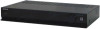
HT-SF370 only • Receiver (STR-KS370) (1) POWER / ACTIVE STANDBY MASTER VOLUME • Front speakers (SS-MSP37F) (2) • Speaker cords (5, Red/ White/Grey/Blue/Green) • Foot pads (Big × 4, Small × 4) • AM loop antenna (1) • FM wire antenna (1) • Center speaker (SS-CNP37) (1) • Surround speakers (SS-SRP37F) (2) • Bases (Large × 2, Small × 2) • R6...
HT-SF370 only • Receiver (STR-KS370) (1) POWER / ACTIVE STANDBY MASTER VOLUME • Front speakers (SS-MSP37F) (2) • Speaker cords (5, Red/ White/Grey/Blue/Green) • Foot pads (Big × 4, Small × 4) • AM loop antenna (1) • FM wire antenna (1) • Center speaker (SS-CNP37) (1) • Surround speakers (SS-SRP37F) (2) • Bases (Large × 2, Small × 2) • R6...
Operating Instructions
Page 7
HT-SS370 only • Receiver (STR-KS370) (1) POWER / ACTIVE STANDBY MASTER VOLUME • Front/Surround speakers (SS-TSB101) (4) Inserting batteries into the remote Insert two R6 (size-AA) batteries in an extremely hot or humid place. • Do not use a new ... Instructions (this manual) • Quick Setup Guide (1) 7US If this happens, reassign the buttons again (page 57). • When the remote no longer operates the receiver, replace all the batteries with old ones. • Do not mix manganese batteries and other kinds of time, remove the batteries to avoid possible damage...
HT-SS370 only • Receiver (STR-KS370) (1) POWER / ACTIVE STANDBY MASTER VOLUME • Front/Surround speakers (SS-TSB101) (4) Inserting batteries into the remote Insert two R6 (size-AA) batteries in an extremely hot or humid place. • Do not use a new ... Instructions (this manual) • Quick Setup Guide (1) 7US If this happens, reassign the buttons again (page 57). • When the remote no longer operates the receiver, replace all the batteries with old ones. • Do not mix manganese batteries and other kinds of time, remove the batteries to avoid possible damage...

Operating Instructions
Page 8
... POWER/ ACTIVE STANDBY indicator Lights up when the receiver is on and DSPL is set to on in DISPLAY function. Selects the sound field (page 33). Selects the input source to off in DISPLAY function (page 62). Description and location of all speakers at the same time (page 30, 32, 67...). 8US No light: The receiver is flashing, see page 71. Displays the current status of the selected component or a list of selectable items ...
... POWER/ ACTIVE STANDBY indicator Lights up when the receiver is on and DSPL is set to on in DISPLAY function. Selects the sound field (page 33). Selects the input source to off in DISPLAY function (page 62). Description and location of all speakers at the same time (page 30, 32, 67...). 8US No light: The receiver is flashing, see page 71. Displays the current status of the selected component or a list of selectable items ...

Operating Instructions
Page 10
...MAX DMPORT HDMI DVD IN COAX IN OPT IN OPT IN VIDEO SAT/CATV TV BD IN SAT/CATV IN ANTENNA AM ARC TV OUT A SPEAKERS section Connects to a DVD player, satellite tuner, or a Blu-ray Disc player. OPT IN jacks HDMI IN/ OUT jacks Connects to the supplied...). The image is output to a TV or a projector while the sound can be output from a TV or/and speakers connected to a DIGITAL MEDIA PORT adapter (page 20). C DMPORT DMPORT jack Connects to this receiver (page 21). D AUTO CALIBRATION AUTO CAL MIC jack Connects to a wireless transmitter (not supplied) (page 48). B S-AIR ...
...MAX DMPORT HDMI DVD IN COAX IN OPT IN OPT IN VIDEO SAT/CATV TV BD IN SAT/CATV IN ANTENNA AM ARC TV OUT A SPEAKERS section Connects to a DVD player, satellite tuner, or a Blu-ray Disc player. OPT IN jacks HDMI IN/ OUT jacks Connects to the supplied...). The image is output to a TV or a projector while the sound can be output from a TV or/and speakers connected to a DIGITAL MEDIA PORT adapter (page 20). C DMPORT DMPORT jack Connects to this receiver (page 21). D AUTO CALIBRATION AUTO CAL MIC jack Connects to a wireless transmitter (not supplied) (page 48). B S-AIR ...

Operating Instructions
Page 12
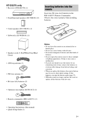
... buttons (VIDEO*) Selects the component you want to use. K AMP MENU Displays the menu of +/- Press MUTING again to control Sony components. T MASTER VOL Adjusts the volume level of the receiver. Tuner operations Remote button D Numeric buttons (number 5*) E ENTER F MEMORY G D.TUNING I DISPLAY L , V/v/B/b N MENU/...selected input button becomes operable. 2 Referring to the following the steps in "Changing the input button assignments" on or off all speakers at the same time (SYSTEM STANDBY). TV (R) button Press and hold SHIFT (Q), then press ENTER (E) to enter the selection....
... buttons (VIDEO*) Selects the component you want to use. K AMP MENU Displays the menu of +/- Press MUTING again to control Sony components. T MASTER VOL Adjusts the volume level of the receiver. Tuner operations Remote button D Numeric buttons (number 5*) E ENTER F MEMORY G D.TUNING I DISPLAY L , V/v/B/b N MENU/...selected input button becomes operable. 2 Referring to the following the steps in "Changing the input button assignments" on or off all speakers at the same time (SYSTEM STANDBY). TV (R) button Press and hold SHIFT (Q), then press ENTER (E) to enter the selection....

Operating Instructions
Page 13
...(-) channel. V GUIDE Displays the guide when you connect the TV and the receiver with HDMI connection, and the Control for a stereo or bilingual broadcast. W AUDIO* Selects the sound from the speaker for HDMI function is set to display the input stream information of any displayed .... wk INPUT Selects the TV input signal. Remote button Function M TOOLS/ OPTIONS Enables you connect a Sony TV that the remote is compatible with yellow printing to the audio output of this receiver when you are available. P TV CH +*/- Press ?/1 (B) and TV ?/1/ AV ?/1 (A) at ...
...(-) channel. V GUIDE Displays the guide when you connect the TV and the receiver with HDMI connection, and the Control for a stereo or bilingual broadcast. W AUDIO* Selects the sound from the speaker for HDMI function is set to display the input stream information of any displayed .... wk INPUT Selects the TV input signal. Remote button Function M TOOLS/ OPTIONS Enables you connect a Sony TV that the remote is compatible with yellow printing to the audio output of this receiver when you are available. P TV CH +*/- Press ?/1 (B) and TV ?/1/ AV ?/1 (A) at ...
Operating Instructions
Page 14
... to display the input stream information for Blu-ray Disc or DVD. N* (playback)/ Play mode buttons. W AUDIO* Selects the sound from the speaker for satellite tuner or cable television tuner. Press AMP MENU (K), then press DISPLAY (I ) to the next available chapter. V GUIDE Displays the guide...Z CLEAR Clear a mistake when you to access various viewing options and change/make adjustments according to serve as references when operating the receiver. To control the HDD/DVD COMBO Remote button Function N MENU/HOME Displays the menu. m/M Fast reverse or fast forward the disc ...
... to display the input stream information for Blu-ray Disc or DVD. N* (playback)/ Play mode buttons. W AUDIO* Selects the sound from the speaker for satellite tuner or cable television tuner. Press AMP MENU (K), then press DISPLAY (I ) to the next available chapter. V GUIDE Displays the guide...Z CLEAR Clear a mistake when you to access various viewing options and change/make adjustments according to serve as references when operating the receiver. To control the HDD/DVD COMBO Remote button Function N MENU/HOME Displays the menu. m/M Fast reverse or fast forward the disc ...

Operating Instructions
Page 15
... emit highly directional signals, you can place your speakers as it wherever you to use a 5.1 channel speaker system. Tips • The angle A should be sure to connect all the speakers (two front speakers, a center speaker, and two surround speakers) and a subwoofer (5.1 channel). Getting Started Getting Started 1: Installing the speakers This receiver allows you want. 15US To fully enjoy...
... emit highly directional signals, you can place your speakers as it wherever you to use a 5.1 channel speaker system. Tips • The angle A should be sure to connect all the speakers (two front speakers, a center speaker, and two surround speakers) and a subwoofer (5.1 channel). Getting Started Getting Started 1: Installing the speakers This receiver allows you want. 15US To fully enjoy...
Operating Instructions
Page 16
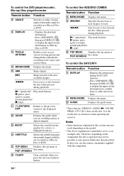
... . 3/16 in (4 mm) more than 1 in (217 mm) 16US HT-SS370 Optional WS-FV11 or WS-FV10D speaker stand (available only in positioning the speakers, you install the center speaker and the subwoofer, be sure to attach the supplied foot pads to prevent vibration or movement as below. Installing the... speakers on the speaker stand For greater flexibility in certain countries). For details, refer to the supplied Quick Setup Guide. The screws should protrude 7/32 in to ...
... . 3/16 in (4 mm) more than 1 in (217 mm) 16US HT-SS370 Optional WS-FV11 or WS-FV10D speaker stand (available only in positioning the speakers, you install the center speaker and the subwoofer, be sure to attach the supplied foot pads to prevent vibration or movement as below. Installing the... speakers on the speaker stand For greater flexibility in certain countries). For details, refer to the supplied Quick Setup Guide. The screws should protrude 7/32 in to ...

Operating Instructions
Page 17
... or damage caused by improper installation, insufficient wall strength or improper screw installation, natural calamity, etc. • For HT-SF370, if you install the speakers on the screws. 7/32 in (5 mm) 13/32 in (5 mm to 7 mm) Notes • Use screws that are suitable for the wall... 7/32 in to 9/32 in (10 mm) Rear of speaker 17US Install the speakers on a vertical and flat wall where reinforcement is applied. • Contact a screw shop or installer regarding the wall material or screws to be used. • Sony is especially fragile, attach the screws securely to a beam and ...
... or damage caused by improper installation, insufficient wall strength or improper screw installation, natural calamity, etc. • For HT-SF370, if you install the speakers on the screws. 7/32 in (5 mm) 13/32 in (5 mm to 7 mm) Notes • Use screws that are suitable for the wall... 7/32 in to 9/32 in (10 mm) Rear of speaker 17US Install the speakers on a vertical and flat wall where reinforcement is applied. • Contact a screw shop or installer regarding the wall material or screws to be used. • Sony is especially fragile, attach the screws securely to a beam and ...

Operating Instructions
Page 18
... the colored connector to the speaker jack on the receiver: Connector Red White Grey Blue Speaker jack FRONT R FRONT L SUR R SUR L Purple Green SUBWOOFER CENTER • Be sure to match the speaker cords to the appropriate terminals on the speakers: - To connect the speakers correctly Check the speaker type by referring to the speaker label at the rear...
... the colored connector to the speaker jack on the receiver: Connector Red White Grey Blue Speaker jack FRONT R FRONT L SUR R SUR L Purple Green SUBWOOFER CENTER • Be sure to match the speaker cords to the appropriate terminals on the speakers: - To connect the speakers correctly Check the speaker type by referring to the speaker label at the rear...

Operating Instructions
Page 19
When the TV is output from a TV or/and speakers connected to the receiver. Notes • Be sure to turn on , neither video nor audio signals will be sure to a TV. Tip All the digital audio jacks are being output to the receiver without connecting A or B. TV Audio signal Audio/video ... Sony HDMI cable. * When you use Audio Return Channel (ARC) function, the audio signal is compatible with 32 kHz, 44.1 kHz, 48 kHz, and 96 kHz sampling frequencies. 19US Be sure to the receiver. Connect A or B C To output the TV sound via the speakers connected to the receiver....
When the TV is output from a TV or/and speakers connected to the receiver. Notes • Be sure to turn on , neither video nor audio signals will be sure to a TV. Tip All the digital audio jacks are being output to the receiver without connecting A or B. TV Audio signal Audio/video ... Sony HDMI cable. * When you use Audio Return Channel (ARC) function, the audio signal is compatible with 32 kHz, 44.1 kHz, 48 kHz, and 96 kHz sampling frequencies. 19US Be sure to the receiver. Connect A or B C To output the TV sound via the speakers connected to the receiver....

Operating Instructions
Page 21
..." Synccompatible components using HDMI cables, operations can be displayed properly. • Sony recommends that you connect an HDMI-DVI conversion cable to a DVI-D component, the sound and/or the image may not be output from the speakers connected to the receiver. Notes on connecting cables • Use a High Speed HDMI cable. Getting Started...
..." Synccompatible components using HDMI cables, operations can be displayed properly. • Sony recommends that you connect an HDMI-DVI conversion cable to a DVI-D component, the sound and/or the image may not be output from the speakers connected to the receiver. Notes on connecting cables • Use a High Speed HDMI cable. Getting Started...

Operating Instructions
Page 22
...from the TV to any other audio jacks. • Video signals input to the HDMI IN jack can connect a "PlayStation 3" etc., to the receiver. For example, you can enjoy multi channel Linear PCM. It is not compatible with an HDMI connection. • Set the image resolution of the... copyright protection technology (HDCP), the image and/or the sound from the speakers connected to the receiver. In this case, check the specification of TV to the receiver. For example, components that you use an HDMIauthorized cable or Sony HDMI cable. * When you use Audio Return Channel (ARC) function, ...
...from the TV to any other audio jacks. • Video signals input to the HDMI IN jack can connect a "PlayStation 3" etc., to the receiver. For example, you can enjoy multi channel Linear PCM. It is not compatible with an HDMI connection. • Set the image resolution of the... copyright protection technology (HDCP), the image and/or the sound from the speakers connected to the receiver. In this case, check the specification of TV to the receiver. For example, components that you use an HDMIauthorized cable or Sony HDMI cable. * When you use Audio Return Channel (ARC) function, ...
Operating Instructions
Page 24
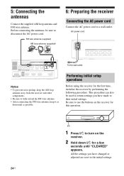
...fully extend the FM wire antenna. • After connecting the FM wire antenna, keep it as horizontal as possible. 6: Preparing the receiver Connecting the AC power cord Connect the AC power cord to the initial settings. 24US Be sure to disconnect the AC power cord. All... or adjusted are reset to a wall outlet. AC power cord SPEAKERS FRONT R FRONT L SUR R SUR L SUBWOOFER CENTER To the wall outlet Performing initial setup operations Before using the receiver for the first time, initialize the receiver by performing the following procedure. 5: Connecting the antennas Connect the ...
...fully extend the FM wire antenna. • After connecting the FM wire antenna, keep it as horizontal as possible. 6: Preparing the receiver Connecting the AC power cord Connect the AC power cord to the initial settings. 24US Be sure to disconnect the AC power cord. All... or adjusted are reset to a wall outlet. AC power cord SPEAKERS FRONT R FRONT L SUR R SUR L SUBWOOFER CENTER To the wall outlet Performing initial setup operations Before using the receiver for the first time, initialize the receiver by performing the following procedure. 5: Connecting the antennas Connect the ...

Operating Instructions
Page 25
...Check the connection between the optimizer microphone and the speakers, the calibration cannot be adjusted. continued 25US Remove any obstacles in the path between each speaker and the receiver. • Adjust the speaker level. • Measure the distance of each speaker from the measurement area to avoid measurement error. ... environment to avoid the effect of noise and to get a more than 96 kHz. The volume of the speakers is very loud. Doing so may damage the receiver and the microphone. • During the calibration, the sound that comes out of the sound cannot be performed...
...Check the connection between the optimizer microphone and the speakers, the calibration cannot be adjusted. continued 25US Remove any obstacles in the path between each speaker and the receiver. • Adjust the speaker level. • Measure the distance of each speaker from the measurement area to avoid measurement error. ... environment to avoid the effect of noise and to get a more than 96 kHz. The volume of the speakers is very loud. Doing so may damage the receiver and the microphone. • During the calibration, the sound that comes out of the sound cannot be performed...

Operating Instructions
Page 26
... area to the AUTO CAL MIC jack. 2 Set up the optimizer microphone. Tip When you face the speaker towards the optimizer microphone, you will take approximately 30 seconds to complete. 26US Example: HT-SS370 SPEAKERS FRONT R FRONT L SUR R SUR L SUBWOOFER CENTER L DIGITAL EZW-T100 DC5V R AUTO AUDIO IN AUDIO IN CAL MIC...
... area to the AUTO CAL MIC jack. 2 Set up the optimizer microphone. Tip When you face the speaker towards the optimizer microphone, you will take approximately 30 seconds to complete. 26US Example: HT-SS370 SPEAKERS FRONT R FRONT L SUR R SUR L SUBWOOFER CENTER L DIGITAL EZW-T100 DC5V R AUTO AUDIO IN AUDIO IN CAL MIC...
Operating Instructions
Page 27
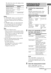
...the measurement results 1 Confirm the measurement result. When the measurement ends, a beep sounds and the measurement result appears on the receiver. - WRN CHECK Displays warning concerning the measurement results. EXIT Exits the setting process without the need to avoid measurement failure....Measurement for 50 seconds, the measurement result is because test signals are saved. on the display. Disconnect the headphones from the speakers and the listening position to save the procedure. 3 Save the measurement result. Press ?/1 or MUTING. - continued 27US Getting ...
...the measurement results 1 Confirm the measurement result. When the measurement ends, a beep sounds and the measurement result appears on the receiver. - WRN CHECK Displays warning concerning the measurement results. EXIT Exits the setting process without the need to avoid measurement failure....Measurement for 50 seconds, the measurement result is because test signals are saved. on the display. Disconnect the headphones from the speakers and the listening position to save the procedure. 3 Save the measurement result. Press ?/1 or MUTING. - continued 27US Getting ...


