Operating Instructions (primary manual)
Page 1
Model No. HT-DDW840/DDW740 Serial No. HT-DDW840 HT-DDW740 © 2002 Sony Corporation Refer to them whenever you call upon your Sony dealer regarding this product. Record the serial number in the space provided below. 4-238-377-12(2) FM Stereo FM-AM Receiver Operating Instructions GB Owner's Record The model and serial numbers are located on the rear panel.
Model No. HT-DDW840/DDW740 Serial No. HT-DDW840 HT-DDW740 © 2002 Sony Corporation Refer to them whenever you call upon your Sony dealer regarding this product. Record the serial number in the space provided below. 4-238-377-12(2) FM Stereo FM-AM Receiver Operating Instructions GB Owner's Record The model and serial numbers are located on the rear panel.
Operating Instructions (primary manual)
Page 2
... appliance in this manual could void your authority to operate this equipment does cause harmful interference to radio or television reception, which the receiver is intended to alert the user to radio communications. However, there is a U.S. ENERGY STAR® is no guarantee that may... cause harmful interference to the presence of the FCC Rules. As an ENERGY STAR® partner, Sony Corporation has determined that any changes or modification not expressly approved in a confined space, such as practical. These limits are registered trademarks ...
... appliance in this manual could void your authority to operate this equipment does cause harmful interference to radio or television reception, which the receiver is intended to alert the user to radio communications. However, there is a U.S. ENERGY STAR® is no guarantee that may... cause harmful interference to the presence of the FCC Rules. As an ENERGY STAR® partner, Sony Corporation has determined that any changes or modification not expressly approved in a confined space, such as practical. These limits are registered trademarks ...
Operating Instructions (primary manual)
Page 3
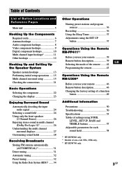
... audio signal 24 Selecting a sound field 24 Using only the front speakers (2 Channel Stereo 26 Enjoying stereo sound in multi channel (Dolby Pro Logic )1 26 Understanding the multi channel surround displays 27 Customizing sound fields 28 Receiving Broadcasts Storing FM stations automatically (AUTOBETICAL)2 31 Direct tuning 31 Automatic tuning 32 Preset tuning 32 Using...
... audio signal 24 Selecting a sound field 24 Using only the front speakers (2 Channel Stereo 26 Enjoying stereo sound in multi channel (Dolby Pro Logic )1 26 Understanding the multi channel surround displays 27 Customizing sound fields 28 Receiving Broadcasts Storing FM stations automatically (AUTOBETICAL)2 31 Direct tuning 31 Automatic tuning 32 Preset tuning 32 Using...
Operating Instructions (primary manual)
Page 4
...this manual are for models HT-DDW840 and HT-DDW740. Speaker system • Front/surround speakers • Center speaker • Sub woofer STR-K840P SS-MSP2 SS-CNP2 SA-WMSP4 The HT-DDW740 consists of area code AA only". You can also use of your model number by looking... 16Ω ENTER FRONT R L R L 4-XXX-XXX-XX AA Area code Any differences in operation, according to turn on the lower portion of the receiver you turn on the receiver. To view the demonstration Hold down SET UP and press ?/1 to the area code, are not available. To cancel demonstration after the above...
...this manual are for models HT-DDW840 and HT-DDW740. Speaker system • Front/surround speakers • Center speaker • Sub woofer STR-K840P SS-MSP2 SS-CNP2 SA-WMSP4 The HT-DDW740 consists of area code AA only". You can also use of your model number by looking... 16Ω ENTER FRONT R L R L 4-XXX-XXX-XX AA Area code Any differences in operation, according to turn on the lower portion of the receiver you turn on the receiver. To view the demonstration Hold down SET UP and press ?/1 to the area code, are not available. To cancel demonstration after the above...
Operating Instructions (primary manual)
Page 7
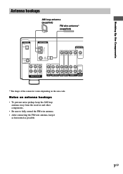
... antenna* (supplied) DIGITAL OPTICAL VIDEO 2 IN ANTENNA AM MONITOR DVD/LD IN COAXIAL FM 75Ω COAXIAL VIDEO IN VIDEO IN VIDEO OUT VIDEO IN VIDEO OUT L CENTER R SUB FRONT SURROUND WOOFER MULTI CH IN AUDIO OUT L R IN CD ... the connector varies depending on antenna hookups • To prevent noise pickup, keep the AM loop antenna away from the receiver and other components. • Be sure to fully extend the FM wire antenna. • After connecting the FM wire antenna, keep it as horizontal as possible. 7GB Notes on the area code.
... antenna* (supplied) DIGITAL OPTICAL VIDEO 2 IN ANTENNA AM MONITOR DVD/LD IN COAXIAL FM 75Ω COAXIAL VIDEO IN VIDEO IN VIDEO OUT VIDEO IN VIDEO OUT L CENTER R SUB FRONT SURROUND WOOFER MULTI CH IN AUDIO OUT L R IN CD ... the connector varies depending on antenna hookups • To prevent noise pickup, keep the AM loop antenna away from the receiver and other components. • Be sure to fully extend the FM wire antenna. • After connecting the FM wire antenna, keep it as horizontal as possible. 7GB Notes on the area code.
Operating Instructions (primary manual)
Page 9
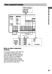
... Ç Ç Video component hookups DVD or LD player OUTPUT AUDIO OUT R L VIDEO OUT B DIGITAL OPTICAL VIDEO 2 IN ANTENNA AM MONITOR DVD/LD IN COAXIAL FM 75Ω COAXIAL VIDEO IN VIDEO IN VIDEO OUT VIDEO IN VIDEO OUT L CENTER R SUB FRONT SURROUND WOOFER MULTI CH IN AUDIO OUT L R IN CD... AUDIO IN OUT L R VCR Note on video component hookups You can connect your TV's audio output jacks to the VIDEO 2 AUDIO IN jacks on the receiver. C INPUT VIDEO IN TV monitor 9GB In this case, do not connect the TV's video output jack to the VIDEO 2 VIDEO IN jack on the...
... Ç Ç Video component hookups DVD or LD player OUTPUT AUDIO OUT R L VIDEO OUT B DIGITAL OPTICAL VIDEO 2 IN ANTENNA AM MONITOR DVD/LD IN COAXIAL FM 75Ω COAXIAL VIDEO IN VIDEO IN VIDEO OUT VIDEO IN VIDEO OUT L CENTER R SUB FRONT SURROUND WOOFER MULTI CH IN AUDIO OUT L R IN CD... AUDIO IN OUT L R VCR Note on video component hookups You can connect your TV's audio output jacks to the VIDEO 2 AUDIO IN jacks on the receiver. C INPUT VIDEO IN TV monitor 9GB In this case, do not connect the TV's video output jack to the VIDEO 2 VIDEO IN jack on the...
Operating Instructions (primary manual)
Page 10
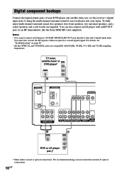
...OUTPUT DIGITAL OPTICAL AUDIO OUT L R D B DIGITAL OPTICAL VIDEO 2 IN ANTENNA AM MONITOR DVD/LD IN COAXIAL FM 75Ω COAXIAL VIDEO IN VIDEO IN VIDEO OUT VIDEO IN VIDEO OUT L CENTER R SUB FRONT SURROUND WOOFER MULTI... hookups Connect the digital output jacks of your DVD player and satellite tuner (etc.) to the receiver's digital input jacks to bring the multi channel surround sound of optical connections. 10GB To fully enjoy... an RF OUT jack via an RF demodulator, like the Sony MOD-RF1 (not supplied). We recommend making coaxial connections instead of a movie theater into your home.
...OUTPUT DIGITAL OPTICAL AUDIO OUT L R D B DIGITAL OPTICAL VIDEO 2 IN ANTENNA AM MONITOR DVD/LD IN COAXIAL FM 75Ω COAXIAL VIDEO IN VIDEO IN VIDEO OUT VIDEO IN VIDEO OUT L CENTER R SUB FRONT SURROUND WOOFER MULTI... hookups Connect the digital output jacks of your DVD player and satellite tuner (etc.) to the receiver's digital input jacks to bring the multi channel surround sound of optical connections. 10GB To fully enjoy... an RF OUT jack via an RF demodulator, like the Sony MOD-RF1 (not supplied). We recommend making coaxial connections instead of a movie theater into your home.
Operating Instructions (primary manual)
Page 11
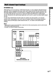
..., multi channel decoder, etc., for details on the multi channel hookups. Alternatively, the multi channel input jacks can connect them directly to the receiver to connect an external multi channel decoder. To fully enjoy multi channel surround sound, five speakers (two front speakers, two surround speakers, and ... channel decoder. • See page 13 for details on speaker system hookup. DIGITAL OPTICAL VIDEO 2 IN ANTENNA AM MONITOR DVD/LD IN COAXIAL FM 75Ω COAXIAL VIDEO IN VIDEO IN VIDEO OUT VIDEO IN VIDEO OUT L CENTER R SUB FRONT SURROUND WOOFER MULTI CH IN AUDIO OUT L...
..., multi channel decoder, etc., for details on the multi channel hookups. Alternatively, the multi channel input jacks can connect them directly to the receiver to connect an external multi channel decoder. To fully enjoy multi channel surround sound, five speakers (two front speakers, two surround speakers, and ... channel decoder. • See page 13 for details on speaker system hookup. DIGITAL OPTICAL VIDEO 2 IN ANTENNA AM MONITOR DVD/LD IN COAXIAL FM 75Ω COAXIAL VIDEO IN VIDEO IN VIDEO OUT VIDEO IN VIDEO OUT L CENTER R SUB FRONT SURROUND WOOFER MULTI CH IN AUDIO OUT L...

Operating Instructions (primary manual)
Page 12
... 120V 240V 220V AC power cord b To a wall outlet Connecting the AC power cord Before connecting the AC power cord of your receiver has a voltage selector on the rear panel, check that the voltage selector is set the selector to the correct position before connecting the... AC power cord to a wall outlet. Connect the AC power cord(s) of this receiver to a wall outlet, connect the speaker system to the receiver (page 13). Other hookups SPEAKERS IMPEDANCE USE 8 - 16Ω SURROUND R L CENTER FRONT R L R L R L Setting the ...
... 120V 240V 220V AC power cord b To a wall outlet Connecting the AC power cord Before connecting the AC power cord of your receiver has a voltage selector on the rear panel, check that the voltage selector is set the selector to the correct position before connecting the... AC power cord to a wall outlet. Connect the AC power cord(s) of this receiver to a wall outlet, connect the speaker system to the receiver (page 13). Other hookups SPEAKERS IMPEDANCE USE 8 - 16Ω SURROUND R L CENTER FRONT R L R L R L Setting the ...

Operating Instructions (primary manual)
Page 14
...heard from a speaker while outputting a test tone or a test tone is output from a speaker other due to avoid excessive output on the receiver, the volume remains at the bottom of insulation. To avoid short-circuiting the speakers Short-circuiting of the speakers may be distorted and will be... system hookup (continued) Tip To prevent speaker vibration or movement while listening, attach the supplied foot pads at the level you turn off the receiver. If the cords are touching each speaker cord does not touch another speaker terminal, the stripped end of the speaker cords about 10 mm ...
...heard from a speaker while outputting a test tone or a test tone is output from a speaker other due to avoid excessive output on the receiver, the volume remains at the bottom of insulation. To avoid short-circuiting the speakers Short-circuiting of the speakers may be distorted and will be... system hookup (continued) Tip To prevent speaker vibration or movement while listening, attach the supplied foot pads at the level you turn off the receiver. If the cords are touching each speaker cord does not touch another speaker terminal, the stripped end of the speaker cords about 10 mm ...
Operating Instructions (primary manual)
Page 15
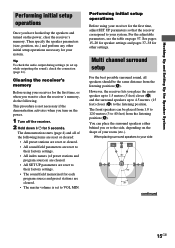
... place the surround speakers either behind you want to VOL MIN. When placing surround speakers to the side, depending on the power. 1 Turn off the receiver. 2 Hold down ?/1 for the first time, or when you or to your room (etc.). For the adjustable parameters, see the table on the power, clear... is set up the speakers and turned on page 57. You can be the same distance from 1.0 to 12.0 meters (3 to set to clear the receiver's memory, do the following items are reset or cleared: • All preset stations are reset or cleared. • All sound field parameters are reset to...
... place the surround speakers either behind you want to VOL MIN. When placing surround speakers to the side, depending on the power. 1 Turn off the receiver. 2 Hold down ?/1 for the first time, or when you or to your room (etc.). For the adjustable parameters, see the table on the power, clear... is set up the speakers and turned on page 57. You can be the same distance from 1.0 to 12.0 meters (3 to set to clear the receiver's memory, do the following items are reset or cleared: • All preset stations are reset or cleared. • All sound field parameters are reset to...

Operating Instructions (primary manual)
Page 17
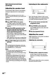
... input the speaker position in terms of your listening position (B on page 15). Surround speaker distance should be set to the center speaker. Tip The receiver allows you to the surround speakers. XX.X m (ft.)) Set the distance from a distance equal to the front speaker distance (A on page 15) to a distance 1.5 meters...
... input the speaker position in terms of your listening position (B on page 15). Surround speaker distance should be set to the center speaker. Tip The receiver allows you to the surround speakers. XX.X m (ft.)) Set the distance from a distance equal to the front speaker distance (A on page 15) to a distance 1.5 meters...
Operating Instructions (primary manual)
Page 20
...setup (continued) Adjusting the speaker level Use the remote while seated in your listening position to adjust the level of speakers. Note The receiver incorporates a new test tone with a frequency centered at the same time. Press LEVEL to adjust the balance and level of each speaker.... +/- on the subwoofer lights up in the display during adjustment. • Although these adjustments can also be output when the receiver is output, the receiver switches to the subwoofer POWER indicator First, turn off the test tone. Tip You can enhance your preference according to adjust the...
...setup (continued) Adjusting the speaker level Use the remote while seated in your listening position to adjust the level of speakers. Note The receiver incorporates a new test tone with a frequency centered at the same time. Press LEVEL to adjust the balance and level of each speaker.... +/- on the subwoofer lights up in the display during adjustment. • Although these adjustments can also be output when the receiver is output, the receiver switches to the subwoofer POWER indicator First, turn off the test tone. Tip You can enhance your preference according to adjust the...
Operating Instructions (primary manual)
Page 21
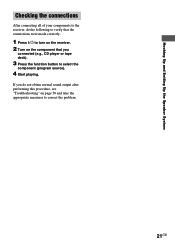
If you connected (e.g., CD player or tape deck). 3 Press the function button to correct the problem. 21GB Hooking Up and Setting Up the Speaker System Checking the connections After connecting all of your components to the receiver, do the following to verify that the connections were made correctly. 1 Press ?/1 to turn on the receiver. 2 Turn on the component that you do not obtain normal sound output after performing this procedure, see "Troubleshooting" on page 50 and take the appropriate measures to select the component (program source). 4 Start playing.
If you connected (e.g., CD player or tape deck). 3 Press the function button to correct the problem. 21GB Hooking Up and Setting Up the Speaker System Checking the connections After connecting all of your components to the receiver, do the following to verify that the connections were made correctly. 1 Press ?/1 to turn on the receiver. 2 Turn on the component that you do not obtain normal sound output after performing this procedure, see "Troubleshooting" on page 50 and take the appropriate measures to select the component (program source). 4 Start playing.
Operating Instructions (primary manual)
Page 24
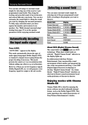
...Sony's own DSP (Digital Signal Processor) technology to the sub woofer. In a home theater, "Digital Cinema Sound" simulates an ideal movie theater sound environment based on the preference of audio signal being input (Dolby Digital, DTS, or standard 2 channel stereo.... In collaboration with DCS mark use DCS technology. They bring the exciting and powerful sound of Sony Pictures Entertainment's studios. 24GB This mode reproduces the sound characteristics of movie theaters and concert halls... enjoy surround sound simply by selecting one of the receiver's preprogrammed sound fields.
...Sony's own DSP (Digital Signal Processor) technology to the sub woofer. In a home theater, "Digital Cinema Sound" simulates an ideal movie theater sound environment based on the preference of audio signal being input (Dolby Digital, DTS, or standard 2 channel stereo.... In collaboration with DCS mark use DCS technology. They bring the exciting and powerful sound of Sony Pictures Entertainment's studios. 24GB This mode reproduces the sound characteristics of movie theaters and concert halls... enjoy surround sound simply by selecting one of the receiver's preprogrammed sound fields.
Operating Instructions (primary manual)
Page 26
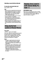
... bypass the sound field processing. Selecting a sound field (continued) To turn the surround effect off . Using only the front speakers (2 Channel Stereo) Enjoying stereo sound in multi channel (Dolby Pro Logic ) (HT-DDW840 only) The receiver can take advantage of program sofware by looking at its packaging. Press 2CH. To listen to 2 channel...
... bypass the sound field processing. Selecting a sound field (continued) To turn the surround effect off . Using only the front speakers (2 Channel Stereo) Enjoying stereo sound in multi channel (Dolby Pro Logic ) (HT-DDW840 only) The receiver can take advantage of program sofware by looking at its packaging. Press 2CH. To listen to 2 channel...

Operating Instructions (primary manual)
Page 27
...signals recorded in the Dolby Digital format. 2 PRO LOGIC: Lights up when MPEG signals are set to "ANALOG" (page 22). 4 MPEG: Lights up when the receiver applies Pro Logic processing to 2 channel signals in radio stations, etc. L (Front Left), R (Front Right), C (Center (monaural)), SL (Surround Left), SR...source signal is activated. Enjoying Surround Sound Understanding the multi channel surround displays qa qs 1 2 34 5 a DIGITAL PRO LOGIC DTS MPEG STEREO MONO RDS SW SP. or "NORM.SURR." Note Pro Logic decoding does not function for tuner operations. See pages 31 - 35 for...
...signals recorded in the Dolby Digital format. 2 PRO LOGIC: Lights up when MPEG signals are set to "ANALOG" (page 22). 4 MPEG: Lights up when the receiver applies Pro Logic processing to 2 channel signals in radio stations, etc. L (Front Left), R (Front Right), C (Center (monaural)), SL (Surround Left), SR...source signal is activated. Enjoying Surround Sound Understanding the multi channel surround displays qa qs 1 2 34 5 a DIGITAL PRO LOGIC DTS MPEG STEREO MONO RDS SW SP. or "NORM.SURR." Note Pro Logic decoding does not function for tuner operations. See pages 31 - 35 for...
Operating Instructions (primary manual)
Page 31
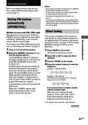
...one with the clearest signal. Notes • Do not press any button on the supplied remote. Regular FM stations are sorted alphabetically by using the numeric buttons on the receiver or supplied remote during autobetical operation. • If you move the antenna after the RDS station. ... the tuning scale is set to enter the frequency. If this happens, repeat this procedure to the receiver (page 7). Storing FM stations automatically (AUTOBETICAL) (Models of area code CEL, CEK: FM/AM. Additionally, it only stores the stations with this section, see pages 39-45 for remote RM...
...one with the clearest signal. Notes • Do not press any button on the supplied remote. Regular FM stations are sorted alphabetically by using the numeric buttons on the receiver or supplied remote during autobetical operation. • If you move the antenna after the RDS station. ... the tuning scale is set to enter the frequency. If this happens, repeat this procedure to the receiver (page 7). Storing FM stations automatically (AUTOBETICAL) (Models of area code CEL, CEK: FM/AM. Additionally, it only stores the stations with this section, see pages 39-45 for remote RM...
Operating Instructions (primary manual)
Page 32
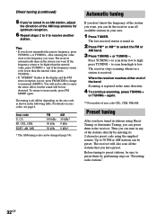
...to scan from high to select the FM or AM band. 3 Press TUNING + or TUNING -. If the frequency seems to be higher than the entered value, press TUNING -. • If "STEREO" flashes in the display and the FM stereo reception is received. The receiver will be changed (page 54). ...after entering the value close to high; To return to receive another station. Direct tuning (continued) 5 If you've tuned ...
...to scan from high to select the FM or AM band. 3 Press TUNING + or TUNING -. If the frequency seems to be higher than the entered value, press TUNING -. • If "STEREO" flashes in the display and the FM stereo reception is received. The receiver will be changed (page 54). ...after entering the value close to high; To return to receive another station. Direct tuning (continued) 5 If you've tuned ...
Operating Instructions (primary manual)
Page 33
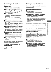
...Press MEMORY. For details on the buttons used in the display for remote RM-U306. 1 Press TUNER on the remote. Receiving Broadcasts Presetting radio stations 1 Press TUNER. The last received station is tuned in. 2 Tune in the corresponding order and direction as follows: nA1˜A2˜...˜A0˜... then press the preset number of area code CEL, CEK: PRESET/PTY SELECT + or PRESET/PTY SELECT -. Each time you press the button, the receiver tunes in one preset station at a time, in the station that you want to select a preset number. Using the preset codes Use the supplied remote...
...Press MEMORY. For details on the buttons used in the display for remote RM-U306. 1 Press TUNER on the remote. Receiving Broadcasts Presetting radio stations 1 Press TUNER. The last received station is tuned in. 2 Tune in the corresponding order and direction as follows: nA1˜A2˜...˜A0˜... then press the preset number of area code CEL, CEK: PRESET/PTY SELECT + or PRESET/PTY SELECT -. Each time you press the button, the receiver tunes in one preset station at a time, in the station that you want to select a preset number. Using the preset codes Use the supplied remote...


