Service Manual
Page 5
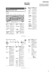
...being input through the COAXIAL jack, or when INPUT MODE is activated. H INPUT MODE Press to select the input mode when the same components are connected to adjust the speed of more than 48 kHz. X-ROUND SPEED Press to both digital and analog jacks (page 62). D"... Remote sensor Receives signals from instruction manual. 5 PL II" lights up when the receiver is not set to "ANALOG" (page 62). Note When playing a DTS format disc, be sure that you have made digital connections and that INPUT MODE is decoding DTS signals. AUTO SW LCR SL SR 8GB STR-K1600 ...
...being input through the COAXIAL jack, or when INPUT MODE is activated. H INPUT MODE Press to select the input mode when the same components are connected to adjust the speed of more than 48 kHz. X-ROUND SPEED Press to both digital and analog jacks (page 62). D"... Remote sensor Receives signals from instruction manual. 5 PL II" lights up when the receiver is not set to "ANALOG" (page 62). Note When playing a DTS format disc, be sure that you have made digital connections and that INPUT MODE is decoding DTS signals. AUTO SW LCR SL SR 8GB STR-K1600 ...
Service Manual
Page 6
... (PR/CR) D SPEAKER section Connects to a TV (page 23). H DVD MENU Press to adjust the TV volume level. Press to perform menu operations. STR-K1600 Ver. 1.1 Rear panel 1 23 DIGITAL OPTICAL SAT IN ANTENNA VIDEO 2/ AM BD IN COAXIAL DVD IN DMPORT L DVD IN VIDEO 2/BD IN OUT HDMI Y...). The COAXIAL jack provides a better COAXIAL IN quality of area code AUS, MY, SP, TH only) to operate the receiver and to control the Sony audio/video components that the remote is assigned to a TV or a projector (page 21). only) AUTO CAL Press to select the FM (RM-AAU015 monaural...
... (PR/CR) D SPEAKER section Connects to a TV (page 23). H DVD MENU Press to adjust the TV volume level. Press to perform menu operations. STR-K1600 Ver. 1.1 Rear panel 1 23 DIGITAL OPTICAL SAT IN ANTENNA VIDEO 2/ AM BD IN COAXIAL DVD IN DMPORT L DVD IN VIDEO 2/BD IN OUT HDMI Y...). The COAXIAL jack provides a better COAXIAL IN quality of area code AUS, MY, SP, TH only) to operate the receiver and to control the Sony audio/video components that the remote is assigned to a TV or a projector (page 21). only) AUTO CAL Press to select the FM (RM-AAU015 monaural...
Service Manual
Page 7
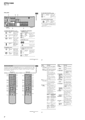
...DVD player or Blu-ray disc player. mode. W TV INPUT Press TV INPUT and TV (M) at the same time to select the TV channels. STR-K1600 Name L TV CH +/- and TV (M) at the same time to activate the buttons with orange printing. preset stations. - Press to select preset...on the function of the button, see the operating instructions supplied with components in the forward/ reverse direction of the VCR or satellite tuner. Notes • The VIDEO 3 button on the remote is not available for receiver operation. • Some functions explained in this section may operate differently ...
...DVD player or Blu-ray disc player. mode. W TV INPUT Press TV INPUT and TV (M) at the same time to select the TV channels. STR-K1600 Name L TV CH +/- and TV (M) at the same time to activate the buttons with orange printing. preset stations. - Press to select preset...on the function of the button, see the operating instructions supplied with components in the forward/ reverse direction of the VCR or satellite tuner. Notes • The VIDEO 3 button on the remote is not available for receiver operation. • Some functions explained in this section may operate differently ...
Service Manual
Page 19
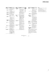
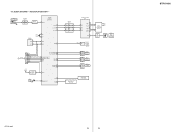
TUNING + F1 FL101 F2 VACUUM FLUORESCENT DISPLAY LED DRIVER Q110 D105 MULTI CHANNEL DECODING SW NETWORK S101-108 SW NETWORK S109-113,115 STR-K1600 19 19 STR-K1600 BLOCK DIAGRAM - KEY/DISPLAY SECTION - J2000 AUTO CAL MIC MIC AMP IC2000 5 1 DETECT D2013,2014 38 ADCC SYSTEM CONTROL IC1101 (5/6) FL_LAT 9 ...IC101 9 8 4 6 2 3 FL DISPLAY DRIVER IC100 9 STB 7 DIN 8 CLK SEG1 14 I I 29 SEG17 • 31 GRID1 42 II GRID11 32 SW1 1 SIRCS 2 OUT REMOTE CONTROL SIGNAL RECEIVER IC103 2 RV102 3 MASTER VOLUME 2 RV101 3 INPUT SELECTOR 2 RV103 3 - 5-5.
TUNING + F1 FL101 F2 VACUUM FLUORESCENT DISPLAY LED DRIVER Q110 D105 MULTI CHANNEL DECODING SW NETWORK S101-108 SW NETWORK S109-113,115 STR-K1600 19 19 STR-K1600 BLOCK DIAGRAM - KEY/DISPLAY SECTION - J2000 AUTO CAL MIC MIC AMP IC2000 5 1 DETECT D2013,2014 38 ADCC SYSTEM CONTROL IC1101 (5/6) FL_LAT 9 ...IC101 9 8 4 6 2 3 FL DISPLAY DRIVER IC100 9 STB 7 DIN 8 CLK SEG1 14 I I 29 SEG17 • 31 GRID1 42 II GRID11 32 SW1 1 SIRCS 2 OUT REMOTE CONTROL SIGNAL RECEIVER IC103 2 RV102 3 MASTER VOLUME 2 RV101 3 INPUT SELECTOR 2 RV103 3 - 5-5.
Service Manual
Page 37
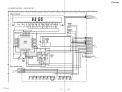
... AD2 AD1 FL_LAT FL_DIN FL_CLK INPUT_JOG_4A INPUT_JOG_4B DCAC_IN CNP106 2P CL004 1 2 DCAC IN DCAC IN DIGITAL M BOARD (4/4) CNS514 (Page 30) Q DCAC BOARD CN2000 (Page 35) STR-K1600 5-23. DISPLAY SECTION - 1 2 3 4 5 6 7 8 DISPLAY BOARD A FL101 VACUUM FLUORESCENT DISPLAY 2 5 6 7 8 9 10 11 12 13 14 15 16 17 18 19 20 ... 22 -14.3 8P JRC SENSOR IC103 C114 0.1 3.3 VCC 3.2 OUT GND 35 GRID8 7G -18.2 36 GRID7 SEG8 21 -12.5 7P SEG7 20 REMOTE CONTROL SIGNAL RECEIVER 6G -18.2 -6.9 6P 123 D 37 GRID6 5G -18.2 38 GRID5 4G -18.2 IC100 IC100 SEG6 19 -10.6 5P SEG5 18 -18 4P...
... AD2 AD1 FL_LAT FL_DIN FL_CLK INPUT_JOG_4A INPUT_JOG_4B DCAC_IN CNP106 2P CL004 1 2 DCAC IN DCAC IN DIGITAL M BOARD (4/4) CNS514 (Page 30) Q DCAC BOARD CN2000 (Page 35) STR-K1600 5-23. DISPLAY SECTION - 1 2 3 4 5 6 7 8 DISPLAY BOARD A FL101 VACUUM FLUORESCENT DISPLAY 2 5 6 7 8 9 10 11 12 13 14 15 16 17 18 19 20 ... 22 -14.3 8P JRC SENSOR IC103 C114 0.1 3.3 VCC 3.2 OUT GND 35 GRID8 7G -18.2 36 GRID7 SEG8 21 -12.5 7P SEG7 20 REMOTE CONTROL SIGNAL RECEIVER 6G -18.2 -6.9 6P 123 D 37 GRID6 5G -18.2 38 GRID5 4G -18.2 IC100 IC100 SEG6 19 -10.6 5P SEG5 18 -18 4P...


