
Operating Instructions
Page 1
4-263-361-11(1) Multi Channel AV Receiver Operating Instructions STR-DH520 ©2011 Sony Corporation
4-263-361-11(1) Multi Channel AV Receiver Operating Instructions STR-DH520 ©2011 Sony Corporation
Operating Instructions
Page 2
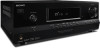
... mains as long as radiators, heat registers, stoves, or other . If the provided plug does not fit into your outlet, consult an electrician for your Sony dealer regarding this apparatus to dripping or splashing, and do not cover the ventilation opening of the apparatus with batteryinstalled to excessive heat such as...
... mains as long as radiators, heat registers, stoves, or other . If the provided plug does not fit into your outlet, consult an electrician for your Sony dealer regarding this apparatus to dripping or splashing, and do not cover the ventilation opening of the apparatus with batteryinstalled to excessive heat such as...

Operating Instructions
Page 3
Other versions may cause harmful interference to qualified service personnel. However, there is no guarantee that to conserve natural resources. Connect the equipment into the apparatus, the apparatus has been exposed to the applicable collection point for the recycling of electrical and electronic equipment. The recycling of materials will help prevent potential negative consequences for the environment and human health, which can radiate radio frequency energy and, if not installed and used , use caution when moving the cart/apparatus combination to avoid injury from that ...
Other versions may cause harmful interference to qualified service personnel. However, there is no guarantee that to conserve natural resources. Connect the equipment into the apparatus, the apparatus has been exposed to the applicable collection point for the recycling of electrical and electronic equipment. The recycling of materials will help prevent potential negative consequences for the environment and human health, which can radiate radio frequency energy and, if not installed and used , use caution when moving the cart/apparatus combination to avoid injury from that ...

Operating Instructions
Page 4
...To ensure that for EMC and product safety is only applicable to the applicable collection point for customers: The following information is Sony Deutschland GmbH, Hedelfinger Strasse 61, 70327 Stuttgart, Germany. The Authorized Representative for safety, performance or data integrity reasons require ... be different from your household waste disposal service or the shop where you will help to the applicable collection point for model STR-DH520. On Copyrights This receiver incorporates Dolby* Digital and Pro Logic Surround and the DTS** Digital Surround System. * Manufactured under...
...To ensure that for EMC and product safety is only applicable to the applicable collection point for customers: The following information is Sony Deutschland GmbH, Hedelfinger Strasse 61, 70327 Stuttgart, Germany. The Authorized Representative for safety, performance or data integrity reasons require ... be different from your household waste disposal service or the shop where you will help to the applicable collection point for model STR-DH520. On Copyrights This receiver incorporates Dolby* Digital and Pro Logic Surround and the DTS** Digital Surround System. * Manufactured under...

Operating Instructions
Page 5
Table of Contents About This Manual 4 Supplied accessories 6 Description and location of parts 7 Getting started 16 Connections 1: Installing the speakers 17 2: Connecting the speakers 19 3: Connecting the TV 21 4a: Connecting the video equipment ...........22 4b: Connecting the audio equipment...........28 5: Connecting the antennas (aerials 28 6: Connecting the AC power cord (mains lead 29 Preparing the Receiver Initializing the receiver 29 Selecting the speaker pattern 30 Using AUTO CALIBRATION 31 (Europe, Australia and Taiwan models only) Adjusting the speaker levels (TEST TONE...
Table of Contents About This Manual 4 Supplied accessories 6 Description and location of parts 7 Getting started 16 Connections 1: Installing the speakers 17 2: Connecting the speakers 19 3: Connecting the TV 21 4a: Connecting the video equipment ...........22 4b: Connecting the audio equipment...........28 5: Connecting the antennas (aerials 28 6: Connecting the AC power cord (mains lead 29 Preparing the Receiver Initializing the receiver 29 Selecting the speaker pattern 30 Using AUTO CALIBRATION 31 (Europe, Australia and Taiwan models only) Adjusting the speaker levels (TEST TONE...
Operating Instructions
Page 6
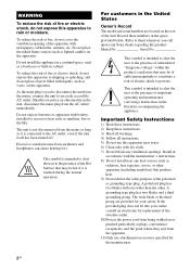
RM-AAU104 (USA and Canada models only) - If this manual) • Quick Setup Guide • FM wire antenna (aerial) (1) • AM loop antenna (aerial) (1) Inserting batteries into the remote control Insert two R6 (size AA) batteries (supplied) by matching 3 and # on the batteries to direct sunlight or lighting apparatuses. Doing so may cause a malfunction. • If you do not intend to use a new battery with new ones. 6GB Supplied accessories • Operating Instructions (this happens, reassign the input buttons (page 61). • When the receiver no longer responds to their...
RM-AAU104 (USA and Canada models only) - If this manual) • Quick Setup Guide • FM wire antenna (aerial) (1) • AM loop antenna (aerial) (1) Inserting batteries into the remote control Insert two R6 (size AA) batteries (supplied) by matching 3 and # on the batteries to direct sunlight or lighting apparatuses. Doing so may cause a malfunction. • If you do not intend to use a new battery with new ones. 6GB Supplied accessories • Operating Instructions (this happens, reassign the input buttons (page 61). • When the receiver no longer responds to their...
Operating Instructions
Page 7
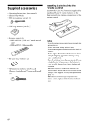
E MASTER VOLUME (page 36, 37) F MUTING (page 37) G DIMMER Adjusts the brightness of parts Front panel 1 2 3 4 5 qs qa q; 9 A ?/1 (on/standby) (page 29, 40, 47) B INPUT SELECTOR (page 36 - 39, 41, 51) C Display panel (page 8) D Remote control sensor Receives signals from remote control. Description and location of the display panel in 3 levels. H DISPLAY (page 38) I 2CH/A.DIRECT, A.F.D., MOVIE/HD-D.C.S., MUSIC (page 43) J TUNING MODE, TUNING +/-, MEMORY/ ENTER (page 39) K INPUT MODE (page 51) L PHONES jack (page 64) 8 76 7GB
E MASTER VOLUME (page 36, 37) F MUTING (page 37) G DIMMER Adjusts the brightness of parts Front panel 1 2 3 4 5 qs qa q; 9 A ?/1 (on/standby) (page 29, 40, 47) B INPUT SELECTOR (page 36 - 39, 41, 51) C Display panel (page 8) D Remote control sensor Receives signals from remote control. Description and location of the display panel in 3 levels. H DISPLAY (page 38) I 2CH/A.DIRECT, A.F.D., MOVIE/HD-D.C.S., MUSIC (page 43) J TUNING MODE, TUNING +/-, MEMORY/ ENTER (page 39) K INPUT MODE (page 51) L PHONES jack (page 64) 8 76 7GB
Operating Instructions
Page 8
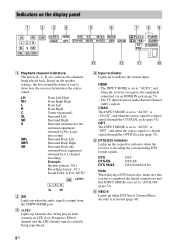
AUTO SW LFE LCR SL SR B SW Lights up when the audio signal is a digital signal through the COAXIAL jack (page 51). Based on the display panel 1 23 4 5 6 7 89 LH RH SW LCR SL S SR SBL SB SBR LFE HDMI DTS -ES 96/24 NEO:6 COAX OPT DTS-HD MSTR HI RES LBR LPCM PL II x z D +EX ST RDS TrueHD SLEEP D.RANGE qd qs qa q; LH RH L R C SL SR S SBL SBR SB Front Left High Front Right High Front Left Front Right Center (monaural) Surround Left Surround Right Surround (monaural or the surround equipment obtained by Pro Logic processing) Surround Back Left Surround Back ...
AUTO SW LFE LCR SL SR B SW Lights up when the audio signal is a digital signal through the COAXIAL jack (page 51). Based on the display panel 1 23 4 5 6 7 89 LH RH SW LCR SL S SR SBL SB SBR LFE HDMI DTS -ES 96/24 NEO:6 COAX OPT DTS-HD MSTR HI RES LBR LPCM PL II x z D +EX ST RDS TrueHD SLEEP D.RANGE qd qs qa q; LH RH L R C SL SR S SBL SBR SB Front Left High Front Right High Front Left Front Right Center (monaural) Surround Left Surround Right Surround (monaural or the surround equipment obtained by Pro Logic processing) Surround Back Left Surround Back ...
Operating Instructions
Page 9
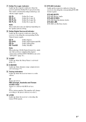
H Dolby Digital Surround indicator Lights up when the Sleep Timer is decoding the corresponding Dolby Digital format signals. I SLEEP Lights up the respective indicator when the receiver is activated (page 13). PL PL II PL IIx PL IIz Dolby Pro Logic Dolby Pro Logic II Dolby Pro Logic IIx Dolby Pro Logic IIz Note These indicators may not light up the respective indicator when the receiver performs Dolby Pro Logic processing. DTS-HD MSTR DTS-HD Master Audio DTS-HD HI RES DTS-HD High Resolution Audio DTS-HD LBR DTS-HD Low Bit Rate Audio 9GB J D.RANGE Lights up the respective...
H Dolby Digital Surround indicator Lights up when the Sleep Timer is decoding the corresponding Dolby Digital format signals. I SLEEP Lights up the respective indicator when the receiver is activated (page 13). PL PL II PL IIx PL IIz Dolby Pro Logic Dolby Pro Logic II Dolby Pro Logic IIx Dolby Pro Logic IIz Note These indicators may not light up the respective indicator when the receiver performs Dolby Pro Logic processing. DTS-HD MSTR DTS-HD Master Audio DTS-HD HI RES DTS-HD High Resolution Audio DTS-HD LBR DTS-HD Low Bit Rate Audio 9GB J D.RANGE Lights up the respective...
Operating Instructions
Page 10
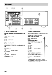
Rear panel 1 1, 2 3 5 1 2 A Audio signal section DIGITAL INPUT/OUTPUT jacks (page 21, 24, 26) HDMI IN/OUT OPTICAL IN COAXIAL IN ANALOG INPUT/OUTPUT jacks (page 21, 26, 28) White (L) AUDIO IN/OUT Red (R) Black AUDIO OUT PORTABLE IN 4 B Video signal section* The image quality depends on the connecting jack. DIGITAL INPUT/OUTPUT jacks (page 21, 24, 25, 26, 27) HDMI IN/OUT COMPONENT VIDEO INPUT/OUTPUT jacks (page 21, 24, 26) Green (Y) Blue (PB) Red (PR) Y, PB, PR IN/OUT COMPOSITE VIDEO INPUT/ OUTPUT jacks (page 21, 26, 27) High quality image Yellow VIDEO IN/OUT * You must ...
Rear panel 1 1, 2 3 5 1 2 A Audio signal section DIGITAL INPUT/OUTPUT jacks (page 21, 24, 26) HDMI IN/OUT OPTICAL IN COAXIAL IN ANALOG INPUT/OUTPUT jacks (page 21, 26, 28) White (L) AUDIO IN/OUT Red (R) Black AUDIO OUT PORTABLE IN 4 B Video signal section* The image quality depends on the connecting jack. DIGITAL INPUT/OUTPUT jacks (page 21, 24, 25, 26, 27) HDMI IN/OUT COMPONENT VIDEO INPUT/OUTPUT jacks (page 21, 24, 26) Green (Y) Blue (PB) Red (PR) Y, PB, PR IN/OUT COMPOSITE VIDEO INPUT/ OUTPUT jacks (page 21, 26, 27) High quality image Yellow VIDEO IN/OUT * You must ...
Operating Instructions
Page 11
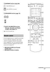
... 0 (Europe, Australia and Taiwan models only) (page 31) ql qa AUTO CAL MIC jack qs Remote control qd Use the supplied remote control to operate Sony audio/ qk qf video equipment. The remote control is assigned to operate this receiver and other equipment. You can reassign the input qj button to...
... 0 (Europe, Australia and Taiwan models only) (page 31) ql qa AUTO CAL MIC jack qs Remote control qd Use the supplied remote control to operate Sony audio/ qk qf video equipment. The remote control is assigned to operate this receiver and other equipment. You can reassign the input qj button to...
Operating Instructions
Page 12
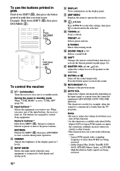
... operation. Scans a station. PRESET +/- or +/- Example: Hold down SHIFT (O), then press ENT/MEM (C). 2 Press ENT/MEM 1 Hold down SHIFT (O), then press ENT/MEM to control Sony equipment. Numeric buttons** Hold down SHIFT (O), then press numeric buttons to preset or tune to both digital and analog jacks. Q MASTER VOL +/- F DISPLAY Views information...
... operation. Scans a station. PRESET +/- or +/- Example: Hold down SHIFT (O), then press ENT/MEM (C). 2 Press ENT/MEM 1 Hold down SHIFT (O), then press ENT/MEM to control Sony equipment. Numeric buttons** Hold down SHIFT (O), then press numeric buttons to preset or tune to both digital and analog jacks. Q MASTER VOL +/- F DISPLAY Views information...
Operating Instructions
Page 13
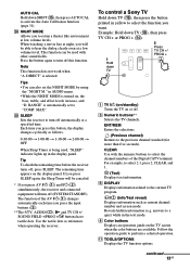
... receiver to select the function you press the input buttons (C). **The 5/TV, AUDIO/ , N and TV CH +/ SOUND FIELD +/PROG +/c buttons have tactile dots. To control a Sony TV Hold down TV A TV ?/1 (on/standby) Turns the TV on , the bass, treble, and effect levels increase, and "D. Example: Hold down TV (P), then press...
... receiver to select the function you press the input buttons (C). **The 5/TV, AUDIO/ , N and TV CH +/ SOUND FIELD +/PROG +/c buttons have tactile dots. To control a Sony TV Hold down TV A TV ?/1 (on/standby) Turns the TV on , the bass, treble, and effect levels increase, and "D. Example: Hold down TV (P), then press...

Operating Instructions
Page 14
Adjusts the TV volume. Use the tactile dots as references when operating the receiver. 14GB Scans for the preset TV channels. Q TV VOL +/- Z INPUT or (Input select) Selects the input signal (TV or video). (Text hold) Holds the current page while in the text mode. Selects the next or previous page while in the text mode. * If you press the input buttons (C). **The 5/TV, AUDIO/ , N and TV CH +/ SOUND FIELD +/PROG +/c buttons have tactile dots. The function of the AV ?/1 (A) changes automatically each time you press AV ?/1 (A) and ?/1 (B) simultaneously, the receiver and connected ...
Adjusts the TV volume. Use the tactile dots as references when operating the receiver. 14GB Scans for the preset TV channels. Q TV VOL +/- Z INPUT or (Input select) Selects the input signal (TV or video). (Text hold) Holds the current page while in the text mode. Selects the next or previous page while in the text mode. * If you press the input buttons (C). **The 5/TV, AUDIO/ , N and TV CH +/ SOUND FIELD +/PROG +/c buttons have tactile dots. The function of the AV ?/1 (A) changes automatically each time you press AV ?/1 (A) and ?/1 (B) simultaneously, the receiver and connected ...
Operating Instructions
Page 15
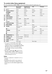
... Pause Stop - - - - x S RETURN/EXIT O T GUIDE or U TOP MENU V AUDIO** or Z INPUT Stop Return Program schedule On-screen guide Audio Select input - X Pause - To control other Sony equipment Be sure to hold down SHIFT (O) to serve as references when operating the receiver. Notes • The above explanation is intended to activate the...
... Pause Stop - - - - x S RETURN/EXIT O T GUIDE or U TOP MENU V AUDIO** or Z INPUT Stop Return Program schedule On-screen guide Audio Select input - X Pause - To control other Sony equipment Be sure to hold down SHIFT (O) to serve as references when operating the receiver. Notes • The above explanation is intended to activate the...
Operating Instructions
Page 16
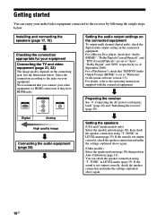
See the illustration below . If the sound is not output correctly, check the speaker connection and make the settings explained above again. 16GB You can enjoy your video equipment via HDMI connection if they have HDMI jacks. For a Blu-ray Disc player, check that "Audio (HDMI)", "Dolby Digital (Coaxial/Optical)", and "DTS (Coaxial/Optical)" are set to "Bitstream" (with the connected equipment. If the sound is not output correctly, check the speaker connection and make the settings explained above again. (Other models) Select the speaker pattern (page 30), then perform Auto...
See the illustration below . If the sound is not output correctly, check the speaker connection and make the settings explained above again. 16GB You can enjoy your video equipment via HDMI connection if they have HDMI jacks. For a Blu-ray Disc player, check that "Audio (HDMI)", "Dolby Digital (Coaxial/Optical)", and "DTS (Coaxial/Optical)" are set to "Bitstream" (with the connected equipment. If the sound is not output correctly, check the speaker connection and make the settings explained above again. (Other models) Select the speaker pattern (page 30), then perform Auto...
Operating Instructions
Page 17
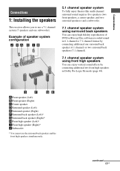
Example of DVD or Blu-ray Disc software recorded sound in 6.1 channel or 7.1 channel format by connecting additional two front high speakers in Dolby Pro Logic IIz mode (page 44). continued 17GB AFront speaker (Left) BFront speaker (Right) CCenter speaker DSurround speaker (Left) ESurround speaker (Right) FSurround back speaker (Left)* GSurround back speaker (Right)* HFront high speaker (Left)* IFront high speaker (Right)* JSubwoofer * You cannot use a 7.1 channel system (7 speakers and one surround back speaker (6.1 channel) or two surround back speakers (7.1 channel). 7.1 channel ...
Example of DVD or Blu-ray Disc software recorded sound in 6.1 channel or 7.1 channel format by connecting additional two front high speakers in Dolby Pro Logic IIz mode (page 44). continued 17GB AFront speaker (Left) BFront speaker (Right) CCenter speaker DSurround speaker (Left) ESurround speaker (Right) FSurround back speaker (Left)* GSurround back speaker (Right)* HFront high speaker (Left)* IFront high speaker (Right)* JSubwoofer * You cannot use a 7.1 channel system (7 speakers and one surround back speaker (6.1 channel) or two surround back speakers (7.1 channel). 7.1 channel ...
Operating Instructions
Page 18
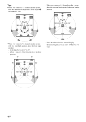
at an angle between 22° to 45°. - at least 1 meter (3.3 feet) directly above the front speakers. • Since the subwoofer does not emit highly directional signals, you can place it wherever you connect a 7.1 channel speaker system with two front high speakers, place the front high speakers - Tips • When you connect a 7.1 channel speaker system with two surround back speakers, all the angles A should be the same. • When you connect a 6.1 channel speaker system, place the surround back speaker behind the seating position. • When you want. 18GB
at an angle between 22° to 45°. - at least 1 meter (3.3 feet) directly above the front speakers. • Since the subwoofer does not emit highly directional signals, you can place it wherever you connect a 7.1 channel speaker system with two front high speakers, place the front high speakers - Tips • When you connect a 7.1 channel speaker system with two surround back speakers, all the angles A should be the same. • When you connect a 6.1 channel speaker system, place the surround back speaker behind the seating position. • When you want. 18GB
Operating Instructions
Page 19
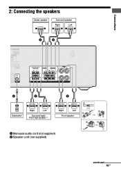
Connections 2: Connecting the speakers Center speaker Surround speaker Right Left B B A B Subwoofer * Right Left Surround back/ Front high speaker** B 1 10 mm (13/32") Right Left 4 2 3 Front speaker 2 4 3 A Monaural audio cord (not supplied) B Speaker cord (not supplied) continued 19GB
Connections 2: Connecting the speakers Center speaker Surround speaker Right Left B B A B Subwoofer * Right Left Surround back/ Front high speaker** B 1 10 mm (13/32") Right Left 4 2 3 Front speaker 2 4 3 A Monaural audio cord (not supplied) B Speaker cord (not supplied) continued 19GB
Operating Instructions
Page 20
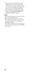
If the auto standby function is set to on the level of the speaker cords are not touching each other within the SPEAKERS terminals. • After you have install and connect your speaker, be output. **If you connect a subwoofer with an auto standby function, turn off the function when watching movies. Notes • Before connecting the cords, be sure to disconnect the AC power cord (mains lead). • Before connecting the AC power cord (mains lead), make sure that metalic wires of the input signal to the subwoofer, and the sound may not be sure to select the speaker pattern from...
If the auto standby function is set to on the level of the speaker cords are not touching each other within the SPEAKERS terminals. • After you have install and connect your speaker, be output. **If you connect a subwoofer with an auto standby function, turn off the function when watching movies. Notes • Before connecting the cords, be sure to disconnect the AC power cord (mains lead). • Before connecting the AC power cord (mains lead), make sure that metalic wires of the input signal to the subwoofer, and the sound may not be sure to select the speaker pattern from...
