Easy Setup Guide
Page 1
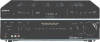
...Cordon audio monophonique Cable de audio monoaural AC OUTLET Speaker cord Cordon d'enceinte Cables de altavoces AUDIO INPUT Sony Corporation © 2005 Printed in Malaysia 4, 5 4, 6 D Sub woofer Caisson de grave Altavoz ...(izquierdo) Surround speaker (left ) Enceinte avant (gauche) Altavoz delantero (izquierdo) A STR-DE898 Easy Setup Guide Guide de réglage rapide Guía de configuración fá...vous référant à l'illustration au verso. 2-580-792-01(1) FM Stereo FM-AM Receiver DVD player Lecteur DVD Reproductor de discos DVD COAXIAL DIGITAL OUT VIDEO OUTPUT TV...
...Cordon audio monophonique Cable de audio monoaural AC OUTLET Speaker cord Cordon d'enceinte Cables de altavoces AUDIO INPUT Sony Corporation © 2005 Printed in Malaysia 4, 5 4, 6 D Sub woofer Caisson de grave Altavoz ...(izquierdo) Surround speaker (left ) Enceinte avant (gauche) Altavoz delantero (izquierdo) A STR-DE898 Easy Setup Guide Guide de réglage rapide Guía de configuración fá...vous référant à l'illustration au verso. 2-580-792-01(1) FM Stereo FM-AM Receiver DVD player Lecteur DVD Reproductor de discos DVD COAXIAL DIGITAL OUT VIDEO OUTPUT TV...
Operating Instructions
Page 1
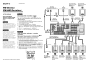
2-580-791-11(3) FM Stereo FM/AM Receiver Operating Instructions Owner's Record The model and serial numbers are located on the rear of the unit. Record the serial number in the space provided below. Model No. Serial No. Refer to them whenever you call upon your Sony dealer regarding this product. STR-DE898 ©2005 Sony Corporation
2-580-791-11(3) FM Stereo FM/AM Receiver Operating Instructions Owner's Record The model and serial numbers are located on the rear of the unit. Record the serial number in the space provided below. Model No. Serial No. Refer to them whenever you call upon your Sony dealer regarding this product. STR-DE898 ©2005 Sony Corporation
Operating Instructions
Page 2
... accordance with the instructions, may be connected to the grounding system of cable entry as practical. As an ENERGY STAR® partner, Sony Corporation has determined that interference will not occur in the literature accompanying the appliance. And don't place lighted candles on a circuit different ...close to correct the interference by turning the equipment off and on, the user is connected. - Increase the separation between the equipment and receiver. - Note to CATV system installer: This reminder is provided to call CATV system installer's attention to Article 820-40 of the NEC ...
... accordance with the instructions, may be connected to the grounding system of cable entry as practical. As an ENERGY STAR® partner, Sony Corporation has determined that interference will not occur in the literature accompanying the appliance. And don't place lighted candles on a circuit different ...close to correct the interference by turning the equipment off and on, the user is connected. - Increase the separation between the equipment and receiver. - Note to CATV system installer: This reminder is provided to call CATV system installer's attention to Article 820-40 of the NEC ...
Operating Instructions
Page 3
...Systems, Inc. 3GB About area codes The area code of the receiver you purchased is for example, "Models of Dolby Laboratories. ** "DTS", "DTS-ES", "Neo:6" and "DTS 96/24" are clearly indicated in the text, for model STR-DE898. "Dolby", "Pro Logic" and the double-D symbol are trademarks... of area code AA only". About This Manual • The instructions in this manual describe the controls on the receiver.
...Systems, Inc. 3GB About area codes The area code of the receiver you purchased is for example, "Models of Dolby Laboratories. ** "DTS", "DTS-ES", "Neo:6" and "DTS 96/24" are clearly indicated in the text, for model STR-DE898. "Dolby", "Pro Logic" and the double-D symbol are trademarks... of area code AA only". About This Manual • The instructions in this manual describe the controls on the receiver.
Operating Instructions
Page 5
...onlyc) Analog disc turntable Multi channel decoder VCR, camcorder, video game, etc. Getting Started 1: Check how to hookup your components Steps 1a through this receiver. Connectable components Component to connect each component. Page 7-8 10-11 7-8 8 or 11 13 7-8 7-8 9 10 12 9 12 12 10 13...etc. b) Model with a DIGITAL OPTICAL OUTPUT or DIGITAL COAXIAL OUTPUT jack, etc. After hooking up your components, proceed to this receiver. This connection is used to output the audio decoded by the component's internal multi channel decoder through 1c beginning on page 7 describe ...
...onlyc) Analog disc turntable Multi channel decoder VCR, camcorder, video game, etc. Getting Started 1: Check how to hookup your components Steps 1a through this receiver. Connectable components Component to connect each component. Page 7-8 10-11 7-8 8 or 11 13 7-8 7-8 9 10 12 9 12 12 10 13...etc. b) Model with a DIGITAL OPTICAL OUTPUT or DIGITAL COAXIAL OUTPUT jack, etc. After hooking up your components, proceed to this receiver. This connection is used to output the audio decoded by the component's internal multi channel decoder through 1c beginning on page 7 describe ...

Operating Instructions
Page 7
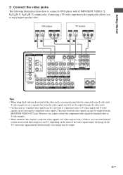
... this case, do not connect the TV's video output jack to the TV/SAT AUDIO IN jacks on the receiver. DVD player OUTPUT DIGITAL COAXIAL F OUTPUT AUDIO OUT L R A DIGITAL OPTICAL ANTENNA TV/SAT IN MD/ TAPE IN S-VIDEO S-VIDEO IN IN AM S-VIDEO S-VIDEO S-VIDEO ...
... this case, do not connect the TV's video output jack to the TV/SAT AUDIO IN jacks on the receiver. DVD player OUTPUT DIGITAL COAXIAL F OUTPUT AUDIO OUT L R A DIGITAL OPTICAL ANTENNA TV/SAT IN MD/ TAPE IN S-VIDEO S-VIDEO IN IN AM S-VIDEO S-VIDEO S-VIDEO ...

Operating Instructions
Page 8
S-video signals are converted upward on this receiver, standard video signals can be converted to component video or S-video signals and S-video signals can only be output. 8GB However, you to standard video .../B-Y, PR/CR/R-Y) output jacks. These upconverted video signals can be converted to your monitor must also be output through the video jacks. • On this receiver and then output to component video signals. are on the TV screen may appear distorted horizontally or no image may be output from a VCR etc.
S-video signals are converted upward on this receiver, standard video signals can be converted to component video or S-video signals and S-video signals can only be output. 8GB However, you to standard video .../B-Y, PR/CR/R-Y) output jacks. These upconverted video signals can be converted to your monitor must also be output through the video jacks. • On this receiver and then output to component video signals. are on the TV screen may appear distorted horizontally or no image may be output from a VCR etc.
Operating Instructions
Page 9
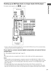
..., VIDEO 1 OUT or VIDEO 2 OUT jacks if you want to the SA-CD/CD OPTICAL IN or SA-CD/CD COAXIAL IN jack on this receiver. Notes • It is output when you make analog connections.
..., VIDEO 1 OUT or VIDEO 2 OUT jacks if you want to the SA-CD/CD OPTICAL IN or SA-CD/CD COAXIAL IN jack on this receiver. Notes • It is output when you make analog connections.
Operating Instructions
Page 10
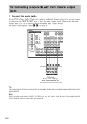
... WOOFER MULTI CH OUT DVD player, Super Audio CD player, Multi channel decoder, etc. Alternatively, the multi channel input jacks can connect it to this receiver's MULTI CH IN jacks to enjoy software with multi channel output jacks 1 Connect the audio jacks. For details on the connected component. 10GB Tip This...
... WOOFER MULTI CH OUT DVD player, Super Audio CD player, Multi channel decoder, etc. Alternatively, the multi channel input jacks can connect it to this receiver's MULTI CH IN jacks to enjoy software with multi channel output jacks 1 Connect the audio jacks. For details on the connected component. 10GB Tip This...
Operating Instructions
Page 11
... output, the image on the TV screen may appear distorted horizontally or no image may be connected via an S-video jack. are on this receiver, standard video signals can be converted to component video or S-video signals and S-video signals can only be output from the video signals and... will not be output through the video jacks. • On this receiver and then output to standard video or S-video signals. • When standard video signals (composite video signals) or S-video signals from a VCR etc. ...
... output, the image on the TV screen may appear distorted horizontally or no image may be connected via an S-video jack. are on this receiver, standard video signals can be converted to component video or S-video signals and S-video signals can only be output from the video signals and... will not be output through the video jacks. • On this receiver and then output to standard video or S-video signals. • When standard video signals (composite video signals) or S-video signals from a VCR etc. ...

Operating Instructions
Page 13
...using the S-video jacks instead of the video jacks, your TV, depending on the status of the video signal output, the image on this receiver, standard video signals can be converted to component video or S-video signals and S-video signals can watch the video from the MONITOR VIDEO OUT jack... signals (composite video signals) or S-video signals from the video signals and will not be output through the video jacks. • On this receiver and then output to your monitor must also be output from the selected input (page 23). These upconverted video signals can only be connected via...
...using the S-video jacks instead of the video jacks, your TV, depending on the status of the video signal output, the image on this receiver, standard video signals can be converted to component video or S-video signals and S-video signals can watch the video from the MONITOR VIDEO OUT jack... signals (composite video signals) or S-video signals from the video signals and will not be output through the video jacks. • On this receiver and then output to your monitor must also be output from the selected input (page 23). These upconverted video signals can only be connected via...
Operating Instructions
Page 14
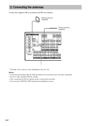
... antenna. Notes • To prevent noise pickup, keep the AM loop antenna away from the receiver and other components. • Be sure to fully extend the FM wire antenna. • After connecting the FM wire antenna, keep it as horizontal as possible. • Do not use the U SIGNAL GND terminal for... grounding the receiver. 14GB AM loop antenna (supplied) FM wire antenna (supplied) DIGITAL OPTICAL ANTENNA TV/SAT IN MD/ TAPE IN S-VIDEO S-VIDEO IN IN AM S-VIDEO S-VIDEO S-VIDEO OUT IN OUT MD...
... antenna. Notes • To prevent noise pickup, keep the AM loop antenna away from the receiver and other components. • Be sure to fully extend the FM wire antenna. • After connecting the FM wire antenna, keep it as horizontal as possible. • Do not use the U SIGNAL GND terminal for... grounding the receiver. 14GB AM loop antenna (supplied) FM wire antenna (supplied) DIGITAL OPTICAL ANTENNA TV/SAT IN MD/ TAPE IN S-VIDEO S-VIDEO IN IN AM S-VIDEO S-VIDEO S-VIDEO OUT IN OUT MD...

Operating Instructions
Page 15
... you to the receiver. You can place it wherever you connect one additional surround back speaker (6.1 channel) or two surround back speakers (7.1 channel) (see "Selecting the surround back decoding ...
... you to the receiver. You can place it wherever you connect one additional surround back speaker (6.1 channel) or two surround back speakers (7.1 channel) (see "Selecting the surround back decoding ...
Operating Instructions
Page 17
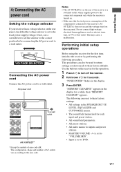
...the AC power cord to the local power supply voltage. Use the buttons on the receiver for the operation. 1 Press ?/1 to turn off the receiver. 2 Hold down ?/1 for the first time, initialize the receiver by performing the following are reset to DVD. 17GB If not, use a screwdriver.... "PUSH ENTER" flashes in the display for models of AC outlets vary according to this outlet. Performing initial setup operations Before using the receiver for 5 seconds. "MEMORY CLEARING" appears in the display. 3 Press ENTER. The following procedure. The configuration, shape and number of area...
...the AC power cord to the local power supply voltage. Use the buttons on the receiver for the operation. 1 Press ?/1 to turn off the receiver. 2 Hold down ?/1 for the first time, initialize the receiver by performing the following are reset to DVD. 17GB If not, use a screwdriver.... "PUSH ENTER" flashes in the display for models of AC outlets vary according to this outlet. Performing initial setup operations Before using the receiver for 5 seconds. "MEMORY CLEARING" appears in the display. 3 Press ENTER. The following procedure. The configuration, shape and number of area...
Operating Instructions
Page 18
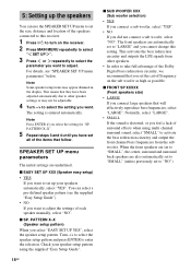
This means that you set the cut off frequency on the receiver. 2 Press MAIN MENU repeatedly to select " SET UP ". 3 Press or repeatedly to select the parameter you want to "NO"). Turn -/+ to select the speaker setup ... adjustable. 4 Turn -/+ to select the setting you want to adjust the settings of the speakers connected to set to "LARGE" and you cannot change this receiver. 1 Press ?/1 to adjust. x EASY SET UP XXX (Speaker easy setup) • YES If you want to turn on the sub woofer as high as possible...
This means that you set the cut off frequency on the receiver. 2 Press MAIN MENU repeatedly to select " SET UP ". 3 Press or repeatedly to select the parameter you want to "NO"). Turn -/+ to select the speaker setup ... adjustable. 4 Turn -/+ to select the setting you want to adjust the settings of the speakers connected to set to "LARGE" and you cannot change this receiver. 1 Press ?/1 to adjust. x EASY SET UP XXX (Speaker easy setup) • YES If you want to turn on the sub woofer as high as possible...

Operating Instructions
Page 20
... an equal distance from your listening position to the closest speaker. If you set the distance from your listening position (B). 20GB x SURR DIST. Tip The receiver lets you set the distance to the surround back speaker. Likewise, the surround speakers and the surround back speakers cannot be no more than 1.5 meters...
... an equal distance from your listening position to the closest speaker. If you set the distance from your listening position (B). 20GB x SURR DIST. Tip The receiver lets you set the distance to the surround back speaker. Likewise, the surround speakers and the surround back speakers cannot be no more than 1.5 meters...

Operating Instructions
Page 22
...test tone with a frequency centered at the same time, press MASTER VOL +/- For details on the receiver. • The adjusted value are shown in sequence. on the remote or turn on the receiver. 2 Press TEST TONE. TEST TONE Adjust the speaker levels and balance while listening to turn MASTER ...VOLUME -/+ on the LEVEL menu settings, see page 37. surround back left and right speakers when surround back speaker selection is output, the receiver switches to "DUAL". - Note Although these adjustments can also be made via the front panel using the remote. 22GB The test tone turns ...
...test tone with a frequency centered at the same time, press MASTER VOL +/- For details on the receiver. • The adjusted value are shown in sequence. on the remote or turn on the receiver. 2 Press TEST TONE. TEST TONE Adjust the speaker levels and balance while listening to turn MASTER ...VOLUME -/+ on the LEVEL menu settings, see page 37. surround back left and right speakers when surround back speaker selection is output, the receiver switches to "DUAL". - Note Although these adjustments can also be made via the front panel using the remote. 22GB The test tone turns ...
Operating Instructions
Page 23
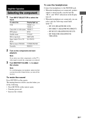
..., you turn off . • When the headphones are connected, speaker output is automatically canceled and the "SP.A" and "SP.B" indications in tuner (FM/AM) TUNER FM/AM Turntable PHONO 2 Turn on the remote. HP THEATER (HEADPHONE THEATER) 23GB HP 2CH (HEADPHONE 2CH) - To select the Display/light up VCR ... tuner TV/SAT MD or tape deck MD/TAPE Super Audio CD or CD SA-CD/CD player Built-in the display turn off the receiver. Note If you select any video components, set the TV's video input to select the input. Amplifier Operation Amplifier Operation Selecting the component 1...
..., you turn off . • When the headphones are connected, speaker output is automatically canceled and the "SP.A" and "SP.B" indications in tuner (FM/AM) TUNER FM/AM Turntable PHONO 2 Turn on the remote. HP THEATER (HEADPHONE THEATER) 23GB HP 2CH (HEADPHONE 2CH) - To select the Display/light up VCR ... tuner TV/SAT MD or tape deck MD/TAPE Super Audio CD or CD SA-CD/CD player Built-in the display turn off the receiver. Note If you select any video components, set the TV's video input to select the input. Amplifier Operation Amplifier Operation Selecting the component 1...
Operating Instructions
Page 24
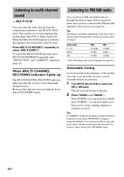
... up if you to select the FM or AM band. Listening to FM/AM radio You can let the receiver scan all available stations in . 2 Press TUNING + or TUNING -. Tip The tuning scale differs depending on area codes, see page 3. Tip If "STEREO" flashes in the display and the FM stereo reception is tuned in your...
... up if you to select the FM or AM band. Listening to FM/AM radio You can let the receiver scan all available stations in . 2 Press TUNING + or TUNING -. Tip The tuning scale differs depending on area codes, see page 3. Tip If "STEREO" flashes in the display and the FM stereo reception is tuned in your...
Operating Instructions
Page 25
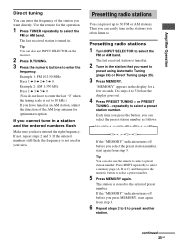
... 3 b 5 b 0 (You do not have to enter the last "0" when the tuning scale is tuned in. 2 Tune in the station that you want directly. The last received station is set to 10 kHz.) If you select the preset station number, start again from step 3. "MEMORY" appears in your area. The last... a station and the entered numbers flash Make sure you want to . Then you can also use INPUT SELECTOR on the receiver. 2 Press D.TUNING. 3 Press the numeric buttons to select the FM or AM band. The station is stored to select a preset station number. If the "MEMORY" indication turns off before...
... 3 b 5 b 0 (You do not have to enter the last "0" when the tuning scale is tuned in. 2 Tune in the station that you want directly. The last received station is set to 10 kHz.) If you select the preset station number, start again from step 3. "MEMORY" appears in your area. The last... a station and the entered numbers flash Make sure you want to . Then you can also use INPUT SELECTOR on the receiver. 2 Press D.TUNING. 3 Press the numeric buttons to select the FM or AM band. The station is stored to select a preset station number. If the "MEMORY" indication turns off before...


