
Limited Warranty (U.S. Only)
Page 1
...against defects in the form of a bill of sale or receipted invoice which vary from your convenience, Sony Electronics Inc. This warranty does not cover customer instruction, installation, set up adjustments or signal reception problems. This warranty does not cover cosmetic damage or ...information or operation, call : 1-800-488-SONY (7669) Printed in the United States. 4-557-173-02 General Stereo/Hifi Components/Tape Decks ® CD Players/Mini Disc Players/Audio Systems Hifi Audio LIMITED WARRANTY Sony Electronics Inc. ("Sony") warrants this Product is invalid if the ...
...against defects in the form of a bill of sale or receipted invoice which vary from your convenience, Sony Electronics Inc. This warranty does not cover customer instruction, installation, set up adjustments or signal reception problems. This warranty does not cover cosmetic damage or ...information or operation, call : 1-800-488-SONY (7669) Printed in the United States. 4-557-173-02 General Stereo/Hifi Components/Tape Decks ® CD Players/Mini Disc Players/Audio Systems Hifi Audio LIMITED WARRANTY Sony Electronics Inc. ("Sony") warrants this Product is invalid if the ...
Operating Instructions
Page 1
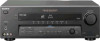
Model No. STR-DE695 © 2003 Sony Corporation 4-247-631-12(1) FM Stereo FM-AM Receiver Operating Instructions Owner's Record The model and serial numbers are located at the rear of the unit. Serial No. Record the serial number in the space provided below. Refer to them whenever you call upon your Sony dealer regarding this product.
Model No. STR-DE695 © 2003 Sony Corporation 4-247-631-12(1) FM Stereo FM-AM Receiver Operating Instructions Owner's Record The model and serial numbers are located at the rear of the unit. Serial No. Record the serial number in the space provided below. Refer to them whenever you call upon your Sony dealer regarding this product.
Operating Instructions
Page 2
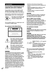
...in particular, specifies that any changes or modification not expressly approved in a residential installation. Increase the separation between the equipment and receiver. - CAUTION You are trademarks of the NEC that provides guidelines for energy efficiency. For customers in cabinet. CAUTION TO PREVENT ...not place objects filled with the limits for help. As an ENERGY STAR® partner, Sony Corporation has determined that interference will not occur in accordance with the instructions, may be connected to the grounding system of cable entry as practical. If this manual...
...in particular, specifies that any changes or modification not expressly approved in a residential installation. Increase the separation between the equipment and receiver. - CAUTION You are trademarks of the NEC that provides guidelines for energy efficiency. For customers in cabinet. CAUTION TO PREVENT ...not place objects filled with the limits for help. As an ENERGY STAR® partner, Sony Corporation has determined that interference will not occur in accordance with the instructions, may be connected to the grounding system of cable entry as practical. If this manual...
Operating Instructions
Page 4
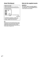
... below). For details on the use the controls on the supplied remote if they have the same or similar names as those on the receiver. Tip The instructions in the text, for the supplied remote RM-PP412 The TV/SAT, PHONO, SOURCE, DIRECT, AAC BI-LING, 12 and ON SCREEN buttons on... the receiver. Note for example, "Models of area code AA only". R RL RL BACK FRONT A FRONT B L L SURROUND KERS IMPEDANCE USE 8-16Ω AC OUTLET 4-XXX-XXX...
... below). For details on the use the controls on the supplied remote if they have the same or similar names as those on the receiver. Tip The instructions in the text, for the supplied remote RM-PP412 The TV/SAT, PHONO, SOURCE, DIRECT, AAC BI-LING, 12 and ON SCREEN buttons on... the receiver. Note for example, "Models of area code AA only". R RL RL BACK FRONT A FRONT B L L SURROUND KERS IMPEDANCE USE 8-16Ω AC OUTLET 4-XXX-XXX...
Operating Instructions
Page 11
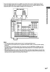
... IN MD/ TAPE OUT CD/ SACD IN DVD IN COAXIAL L ANTENNA COMPONENT VIDEO Y MONITOR PB/B-Y AM y FM 75Ω COAXIAL VIDEO IN VIDEO IN VIDEO OUT VIDEO IN VIDEO OUT DVD VIDEO 2 IN IN CTRL A1...kHz and 32 kHz sampling frequencies. • It is not output when you to the operating instructions supplied with only digital connections. To record analog signals, make digital connections. • The sound... this unit. To record digital signals, make analog connections. Connect to the receiver's digital output jack. Hooking Up the Components ç ç Connect the digital output jacks...
... IN MD/ TAPE OUT CD/ SACD IN DVD IN COAXIAL L ANTENNA COMPONENT VIDEO Y MONITOR PB/B-Y AM y FM 75Ω COAXIAL VIDEO IN VIDEO IN VIDEO OUT VIDEO IN VIDEO OUT DVD VIDEO 2 IN IN CTRL A1...kHz and 32 kHz sampling frequencies. • It is not output when you to the operating instructions supplied with only digital connections. To record analog signals, make digital connections. • The sound... this unit. To record digital signals, make analog connections. Connect to the receiver's digital output jack. Hooking Up the Components ç ç Connect the digital output jacks...
Operating Instructions
Page 12
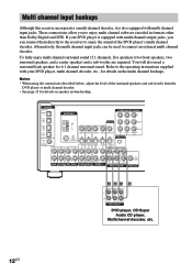
... a surround back speaker for details on speaker system hookup. Refer to the operating instructions supplied with your DVD player is also equipped with multi channel output jacks, you ...you can be used to connect an external multi channel decoder. Multi channel input hookups Although this receiver incorporates a multi channel decoder, it is equipped with multi channel input jacks. DIGITAL OPTICAL VIDEO...TAPE OUT CD/ SACD IN DVD IN COAXIAL L ANTENNA COMPONENT VIDEO Y MONITOR PB/B-Y AM y FM 75Ω COAXIAL VIDEO IN VIDEO IN VIDEO OUT VIDEO IN VIDEO OUT DVD VIDEO 2 IN IN...
... a surround back speaker for details on speaker system hookup. Refer to the operating instructions supplied with your DVD player is also equipped with multi channel output jacks, you ...you can be used to connect an external multi channel decoder. Multi channel input hookups Although this receiver incorporates a multi channel decoder, it is equipped with multi channel input jacks. DIGITAL OPTICAL VIDEO...TAPE OUT CD/ SACD IN DVD IN COAXIAL L ANTENNA COMPONENT VIDEO Y MONITOR PB/B-Y AM y FM 75Ω COAXIAL VIDEO IN VIDEO IN VIDEO OUT VIDEO IN VIDEO OUT DVD VIDEO 2 IN IN...
Operating Instructions
Page 13
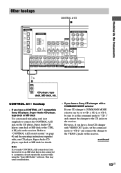
... or MD deck to the VIDEO 2 jacks on page 40 and the operating instructions supplied with VIDEO OUT jacks, set the command mode to "CD 1" and connect the changer to a computer, do not operate the receiver while using the "Sony MD Editor" software. This may cause a malfunction. • If you make ... is also connected to the CD jacks on the receiver. Hooking Up the Components Other hookups CONTROL A1 I DIGITAL OPTICAL VIDEO 2 IN MD/ TAPE IN MD/ TAPE OUT CD/ SACD IN DVD IN COAXIAL L ANTENNA COMPONENT VIDEO Y MONITOR PB/B-Y AM y FM 75Ω COAXIAL VIDEO IN VIDEO IN VIDEO OUT...
... or MD deck to the VIDEO 2 jacks on page 40 and the operating instructions supplied with VIDEO OUT jacks, set the command mode to "CD 1" and connect the changer to a computer, do not operate the receiver while using the "Sony MD Editor" software. This may cause a malfunction. • If you make ... is also connected to the CD jacks on the receiver. Hooking Up the Components Other hookups CONTROL A1 I DIGITAL OPTICAL VIDEO 2 IN MD/ TAPE IN MD/ TAPE OUT CD/ SACD IN DVD IN COAXIAL L ANTENNA COMPONENT VIDEO Y MONITOR PB/B-Y AM y FM 75Ω COAXIAL VIDEO IN VIDEO IN VIDEO OUT...

Operating Instructions
Page 37
... components of the same kind. If you are not familiar with how to the MD/TAPE jacks. 1 To name a preset station Press TUNER FM/AM, then tune in the display. Note that no more than one name can record on page 36. It is useful for another station or...CUSTOM ". 3 Press or repeatedly to select "NAME IN". 4 Create an index name by using the receiver. To name a program source Select the program source (component) to be specified as "VHS" and "8MM", respectively. See the operating instructions of your cassette deck or MD deck if you want . 5 Press ENTER. 6 Repeat steps 2 to...
... components of the same kind. If you are not familiar with how to the MD/TAPE jacks. 1 To name a preset station Press TUNER FM/AM, then tune in the display. Note that no more than one name can record on page 36. It is useful for another station or...CUSTOM ". 3 Press or repeatedly to select "NAME IN". 4 Create an index name by using the receiver. To name a program source Select the program source (component) to be specified as "VHS" and "8MM", respectively. See the operating instructions of your cassette deck or MD deck if you want . 5 Press ENTER. 6 Repeat steps 2 to...
Operating Instructions
Page 38
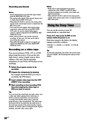
...selected, no signals are output from DIGITAL OUT jacks (MD/TAPE OPTICAL OUT). See the operating instructions of your VCR or DVD player if you may not be able to be recorded onto the audio...the REC OUT jacks. The remaining time appears in the display. 38US You can set the receiver to start recording from another audio source, select the program source, then start playing the video ... t 1-30-00 t 1-00-00 t 0-30-00 t OFF Tip To check the remaining time before the receiver turns off automatically at a specified time. Locate the point where you make both digital and analog connections to the...
...selected, no signals are output from DIGITAL OUT jacks (MD/TAPE OPTICAL OUT). See the operating instructions of your VCR or DVD player if you may not be able to be recorded onto the audio...the REC OUT jacks. The remaining time appears in the display. 38US You can set the receiver to start recording from another audio source, select the program source, then start playing the video ... t 1-30-00 t 1-00-00 t 0-30-00 t OFF Tip To check the remaining time before the receiver turns off automatically at a specified time. Locate the point where you make both digital and analog connections to the...
Operating Instructions
Page 40
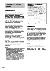
...personal computer running "MD Editor" or similar application. You can be controlled may be sure to also refer to the Operating Instructions supplied with integrated systems. Currently, CONTROL A1II connections between components with CONTROL A1 jacks and components with the new functions. &#... 1 CD player, 1 MD deck, 1 tape deck and 1 receiver). (You may be connected to the CONTROL A1II jacks on the component. However, when making connections between a Sony CD player, amplifier (receiver), MD deck and cassette deck provide automatic function selection and synchronized recording....
...personal computer running "MD Editor" or similar application. You can be controlled may be sure to also refer to the Operating Instructions supplied with integrated systems. Currently, CONTROL A1II connections between components with CONTROL A1 jacks and components with the new functions. &#... 1 CD player, 1 MD deck, 1 tape deck and 1 receiver). (You may be connected to the CONTROL A1II jacks on the component. However, when making connections between a Sony CD player, amplifier (receiver), MD deck and cassette deck provide automatic function selection and synchronized recording....
Operating Instructions
Page 41
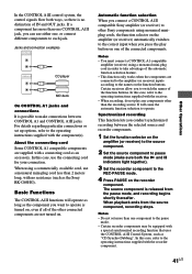
...selection to operate. Notes • You must connect a CONTROL A1 compatible amplifier (receiver) using a commercially available cord, use the connecting cord for your connection. It will operate as long as the Sony RK-G69HG). Synchronized recording This function lets you can use either one of the...to make sure both ways, so there is released from the source component, recording stops. In this case, refer to the operating instructions supplied with a special synchronized recording function that uses the CONTROL A1II Control System, such as an accessory. Other Operations In the ...
...selection to operate. Notes • You must connect a CONTROL A1 compatible amplifier (receiver) using a commercially available cord, use the connecting cord for your connection. It will operate as long as the Sony RK-G69HG). Synchronized recording This function lets you can use either one of the...to make sure both ways, so there is released from the source component, recording stops. In this case, refer to the operating instructions supplied with a special synchronized recording function that uses the CONTROL A1II Control System, such as an accessory. Other Operations In the ...
Marketing Specifications
Page 2
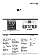
...and logos are registered trademarks of their respective owners. TBD Key Technology STR-DE695 Receiver Component Video Switching 2 Component Video Inputs,1 Component Video Output HD Switching,...• 6 Channel Power Rating: 100 Watts Per Channel x 6 (8 ohms 1 kHz, THD 0.7%) • FM Tuning Range: 87.5 - 108 MHz • AM Tuning Range: 530 - 1710 kHz • Display Type...Standby): 0.3 Watts Supplied Accessories • Instruction Manual • Remote Model: RM- All rights reserved. Weight: TBD UPC Code • 027242618176 ©2003 Sony Electronics Inc. PP412 Weights & Measures &#...
...and logos are registered trademarks of their respective owners. TBD Key Technology STR-DE695 Receiver Component Video Switching 2 Component Video Inputs,1 Component Video Output HD Switching,...• 6 Channel Power Rating: 100 Watts Per Channel x 6 (8 ohms 1 kHz, THD 0.7%) • FM Tuning Range: 87.5 - 108 MHz • AM Tuning Range: 530 - 1710 kHz • Display Type...Standby): 0.3 Watts Supplied Accessories • Instruction Manual • Remote Model: RM- All rights reserved. Weight: TBD UPC Code • 027242618176 ©2003 Sony Electronics Inc. PP412 Weights & Measures &#...


