Operating Instructions (Receiver)
Page 1
4-227-987-13(1) FM Stereo FM-AM Receiver Operating Instructions STR-DE545 STR-DE445 STR-SE501 © 2000 Sony Corporation
4-227-987-13(1) FM Stereo FM-AM Receiver Operating Instructions STR-DE545 STR-DE445 STR-SE501 © 2000 Sony Corporation
Operating Instructions (Receiver)
Page 2
... FCC Rules. Note to CATV system installer: This reminder is encouraged to try to radio or television reception, which the receiver is connected. - STR-DE545/DE445/SE501 Serial No. The operating voltage is indicated on , the user is provided to call upon your authority to radio...174; guidelines for help. Consult the dealer or an experienced radio/TV technician for energy efficiency. As an ENERGY STAR® partner, Sony Corporation has determined that provides guidelines for a Class B digital device, pursuant to the presence of the unit. On operation Before connecting other...
... FCC Rules. Note to CATV system installer: This reminder is encouraged to try to radio or television reception, which the receiver is connected. - STR-DE545/DE445/SE501 Serial No. The operating voltage is indicated on , the user is provided to call upon your authority to radio...174; guidelines for help. Consult the dealer or an experienced radio/TV technician for energy efficiency. As an ENERGY STAR® partner, Sony Corporation has determined that provides guidelines for a Class B digital device, pursuant to the presence of the unit. On operation Before connecting other...
Operating Instructions (Receiver)
Page 3
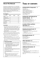
.... Notes • Running the demonstration will be cleared, see "Clearing the receiver's memory" on the receiver. In this manual, the STRDE545 and the remote commander RM-U304 are for the STR-DE545, STR-DE445 and STR-SE501. Type of the remote RM-PP404 (STR-DE545 and STR-SE501 only), refer to the separate operating instructions supplied with the remote...
.... Notes • Running the demonstration will be cleared, see "Clearing the receiver's memory" on the receiver. In this manual, the STRDE545 and the remote commander RM-U304 are for the STR-DE545, STR-DE445 and STR-SE501. Type of the remote RM-PP404 (STR-DE545 and STR-SE501 only), refer to the separate operating instructions supplied with the remote...
Operating Instructions (Receiver)
Page 4
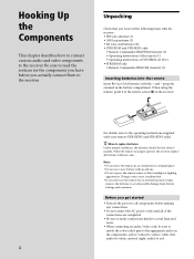
... the sections for the components you have before you actually connect them to the receiver. 4 Unpacking Check that you received the following items with the receiver: • FM wire antenna (1) • AM loop antenna (1) • R6 (size-AA) batteries (2) • STR-DE545 and STR-SE501 only • Remote Commander RM-PP404 (remote) (1) • Operating instructions of the...
... the sections for the components you have before you actually connect them to the receiver. 4 Unpacking Check that you received the following items with the receiver: • FM wire antenna (1) • AM loop antenna (1) • R6 (size-AA) batteries (2) • STR-DE545 and STR-SE501 only • Remote Commander RM-PP404 (remote) (1) • Operating instructions of the...

Operating Instructions (Receiver)
Page 5
... noise pickup, keep the AM loop antenna away from the receiver and other components. • Be sure to fully extend the FM wire antenna. • After connecting the FM wire antenna, keep it against lightning. Outdoor FM antenna Receiver FM 75Ω COAXIAL AM ANTENNA Ground wire (not supplied) ...To ground Important If you have poor FM reception Use a 75-ohm coaxial cable (not...
... noise pickup, keep the AM loop antenna away from the receiver and other components. • Be sure to fully extend the FM wire antenna. • After connecting the FM wire antenna, keep it against lightning. Outdoor FM antenna Receiver FM 75Ω COAXIAL AM ANTENNA Ground wire (not supplied) ...To ground Important If you have poor FM reception Use a 75-ohm coaxial cable (not...
Operating Instructions (Receiver)
Page 7
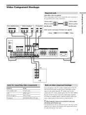
...) White (L/audio) Red (R/audio) Yellow (video) White (L/audio) Red (R/audio) INPUT VIDEO IN S-VIDEO IN Video cord for connecting a TV monitor (not supplied) Yellow Yellow FM 75Ω COAXIAL AM DIGITAL IN TV/SAT DVD/LD MONITOR CTRL A1 I I VIDEO IN VIDEO IN VIDEO OUT VIDEO IN VIDEO OUT ANTENNA L OPTICAL... cords Audio/video cords (not supplied) When connecting a cord, be connected via an S-video jack. z When using the S-video jacks instead of the video jacks (STR-DE545 and STR-SE501 only) Your monitor must also be sure to match the color-coded pins to the receiver as shown above.
...) White (L/audio) Red (R/audio) Yellow (video) White (L/audio) Red (R/audio) INPUT VIDEO IN S-VIDEO IN Video cord for connecting a TV monitor (not supplied) Yellow Yellow FM 75Ω COAXIAL AM DIGITAL IN TV/SAT DVD/LD MONITOR CTRL A1 I I VIDEO IN VIDEO IN VIDEO OUT VIDEO IN VIDEO OUT ANTENNA L OPTICAL... cords Audio/video cords (not supplied) When connecting a cord, be connected via an S-video jack. z When using the S-video jacks instead of the video jacks (STR-DE545 and STR-SE501 only) Your monitor must also be sure to match the color-coded pins to the receiver as shown above.
Operating Instructions (Receiver)
Page 8
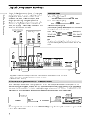
...then connect the RF demodulator's optical or coaxial digital output to the coaxial jack. ** STR-DE545 and STR-SE501 only. D. 2CH MODE I VIDEO IN VIDEO IN VIDEO OUT VIDEO IN VIDEO ...SWITCHED 120W/1A MAX AC 120V 60Hz * When making connections as the Sony MOD-RF1 (not supplied). Example of 32 kHz, 44.1 kHz, and 48kHz. The receiver may not operate correctly if INPUT MODE is recommended to make digital ...TAPE CD TUNER AUX CINEMA STUDIO A B C SOUND FIELD A. TUNING + MEMORY FM/AM FM MODE MUTING BASS BOOST TONE Note When making digital audio connections to a DVD player...
...then connect the RF demodulator's optical or coaxial digital output to the coaxial jack. ** STR-DE545 and STR-SE501 only. D. 2CH MODE I VIDEO IN VIDEO IN VIDEO OUT VIDEO IN VIDEO ...SWITCHED 120W/1A MAX AC 120V 60Hz * When making connections as the Sony MOD-RF1 (not supplied). Example of 32 kHz, 44.1 kHz, and 48kHz. The receiver may not operate correctly if INPUT MODE is recommended to make digital ...TAPE CD TUNER AUX CINEMA STUDIO A B C SOUND FIELD A. TUNING + MEMORY FM/AM FM MODE MUTING BASS BOOST TONE Note When making digital audio connections to a DVD player...

Operating Instructions (Receiver)
Page 9
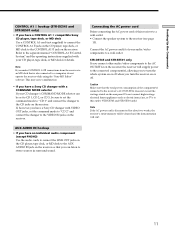
... F. Front Speaker (L) Front Speaker (R) Rear Speaker (L) Rear Speaker (R) Center Speaker Active Woofer 9 Hooking Up the Components 5.1CH Input Hookups Although this receiver incorporates a multi channel decoder, it is equipped with 5.1CH OUTPUT jacks, you will need five speakers (two front speakers, two rear speakers, and a...CENTER and WOOFER jacks Black Black Video cord (not supplied) One for details on the 5.1 channel input hookups. TUNING + MEMORY FM/AM FM MODE MUTING BASS BOOST TONE SPEAKERS REAR/CENTER SUB WOOFER Note See page 13 for the DVD/LD VIDEO IN jacks (etc.) ...
... F. Front Speaker (L) Front Speaker (R) Rear Speaker (L) Rear Speaker (R) Center Speaker Active Woofer 9 Hooking Up the Components 5.1CH Input Hookups Although this receiver incorporates a multi channel decoder, it is equipped with 5.1CH OUTPUT jacks, you will need five speakers (two front speakers, two rear speakers, and a...CENTER and WOOFER jacks Black Black Video cord (not supplied) One for details on the 5.1 channel input hookups. TUNING + MEMORY FM/AM FM MODE MUTING BASS BOOST TONE SPEAKERS REAR/CENTER SUB WOOFER Note See page 13 for the DVD/LD VIDEO IN jacks (etc.) ...
Operating Instructions (Receiver)
Page 11
...component(s) connected to the CONTROL A1 jack on the receiver. STR-DE545 and STR-SE501 only If you connect other audio/video components to the AC OUTLET(s) on the receiver, the receiver will supply power to the connected component(s), allowing you to stereo sources in surround sound. Refer to the separate ... player, tape deck, or MD deck for about two weeks, the receiver's entire memory will start. 11 Hooking Up the Components CONTROL A1 hookup (STR-DE545 and STR-SE501 only) • If you have a CONTROL A1 compatible Sony CD player, tape deck, or MD deck Use a CONTROL A1 cord...
...component(s) connected to the CONTROL A1 jack on the receiver. STR-DE545 and STR-SE501 only If you connect other audio/video components to the AC OUTLET(s) on the receiver, the receiver will supply power to the connected component(s), allowing you to stereo sources in surround sound. Refer to the separate ... player, tape deck, or MD deck for about two weeks, the receiver's entire memory will start. 11 Hooking Up the Components CONTROL A1 hookup (STR-DE545 and STR-SE501 only) • If you have a CONTROL A1 compatible Sony CD player, tape deck, or MD deck Use a CONTROL A1 cord...
Operating Instructions (Receiver)
Page 12
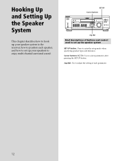
... UP NAME ENTER BASS BOOST TONE MASTER VOLUME PRESET - D. 2CH MODE I - TUNING + MEMORY FM/AM FM MODE MUTING BASS BOOST TONE Jog dial Brief descriptions of each speaker, and how to set up your speaker system to the receiver, how to position each parameter. 12 Jog dial: Use to adjust the setting of...
... UP NAME ENTER BASS BOOST TONE MASTER VOLUME PRESET - D. 2CH MODE I - TUNING + MEMORY FM/AM FM MODE MUTING BASS BOOST TONE Jog dial Brief descriptions of each speaker, and how to set up your speaker system to the receiver, how to position each parameter. 12 Jog dial: Use to adjust the setting of...
Operating Instructions (Receiver)
Page 13
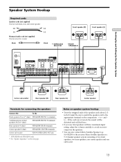
...woofer Black (+) (-) Black **IMPEDANCE SELECTOR } Front speaker (R) * FRONT SPEAKERS B }] Front speaker (L) FM 75Ω COAXIAL AM DIGITAL IN TV/SAT DVD/LD MONITOR CTRL A1 I I VIDEO IN VIDEO IN... front speakers with low maximum input rating, adjust the volume carefully to the receiver. Be sure to match the speaker cord to the appropriate terminal on the ...REAR terminals Center speaker (8 ohm) SPEAKERS CENTER terminals Active sub woofer SUB WOOFER AUDIO OUT jack * STR-DE545 and STR-SE501 only. ** See "Speaker impedance" on speaker system hookup • Twist the stripped ends ...
...woofer Black (+) (-) Black **IMPEDANCE SELECTOR } Front speaker (R) * FRONT SPEAKERS B }] Front speaker (L) FM 75Ω COAXIAL AM DIGITAL IN TV/SAT DVD/LD MONITOR CTRL A1 I I VIDEO IN VIDEO IN... front speakers with low maximum input rating, adjust the volume carefully to the receiver. Be sure to match the speaker cord to the appropriate terminal on the ...REAR terminals Center speaker (8 ohm) SPEAKERS CENTER terminals Active sub woofer SUB WOOFER AUDIO OUT jack * STR-DE545 and STR-SE501 only. ** See "Speaker impedance" on speaker system hookup • Twist the stripped ends ...
Operating Instructions (Receiver)
Page 14
... speakers with your speakers if you're not sure of their impedance. (This information is touching another speaker cord. Speaker impedance (STR-DE545 and STR-SE501 only) Set the IMPEDANCE SELECTOR for the front speakers as indicated in the table below. Stripped cords are connected correctly. If...speaker cord Stripped speaker cord is usually printed on a label on the receiver, the speaker may damage the receiver. For details on the receiver, the volume remains at the level you turn off the receiver. 14 Hooking Up and Setting Up the Speaker System Speaker System Hookup ...
... speakers with your speakers if you're not sure of their impedance. (This information is touching another speaker cord. Speaker impedance (STR-DE545 and STR-SE501 only) Set the IMPEDANCE SELECTOR for the front speakers as indicated in the table below. Stripped cords are connected correctly. If...speaker cord Stripped speaker cord is usually printed on a label on the receiver, the speaker may damage the receiver. For details on the receiver, the volume remains at the level you turn off the receiver. 14 Hooking Up and Setting Up the Speaker System Speaker System Hookup ...

Operating Instructions (Receiver)
Page 15
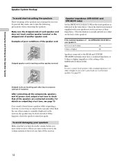
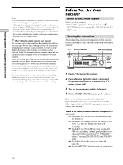
... selector" on how to adjust each program source and preset stations are reset to clear the receiver's memory, do the following items. For details on page 23). (STR-DE545 and STR-SE501 only). Then specify the speaker parameters (size, position, etc.) and perform any other initial... setup operations necessary for your system. TUNING + MEMORY FM/AM FM MODE MUTING BASS BOOST TONE Performing initial setup operations Before you use your receiver for the ...
... selector" on how to adjust each program source and preset stations are reset to clear the receiver's memory, do the following items. For details on page 23). (STR-DE545 and STR-SE501 only). Then specify the speaker parameters (size, position, etc.) and perform any other initial... setup operations necessary for your system. TUNING + MEMORY FM/AM FM MODE MUTING BASS BOOST TONE Performing initial setup operations Before you use your receiver for the ...
Operating Instructions (Receiver)
Page 16
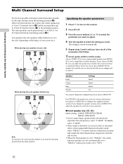
...if you're using normal speakers and MICRO SP if you're using multi channel surround sound, select "SMALL" to the side, depending on the receiver. 2 Press SET UP. 3 Press the cursor buttons ( or ) to select the parameter you have set to the listening position. SP, ... channel bass frequencies from the listening position than the front speakers. SP to your room (etc.). x Front speaker size ( L R ) Initial setting : LARGE (STR-DE545/DE445) SMALL (STR-SE501) • If you feel a lack of your side B A A 45° C C 90° 20° When placing the rear speakers behind ...
...if you're using normal speakers and MICRO SP if you're using multi channel surround sound, select "SMALL" to the side, depending on the receiver. 2 Press SET UP. 3 Press the cursor buttons ( or ) to select the parameter you have set to the listening position. SP, ... channel bass frequencies from the listening position than the front speakers. SP to your room (etc.). x Front speaker size ( L R ) Initial setting : LARGE (STR-DE545/DE445) SMALL (STR-SE501) • If you feel a lack of your side B A A 45° C C 90° 20° When placing the rear speakers behind ...
Operating Instructions (Receiver)
Page 19
... the volume level of the rear speaker, press MENU to select the rear parameter. Likewise, the rear speakers cannot be output when the receiver is not conducive to enjoy the surround sound. If you cannot obtain a satisfactory surround effect because the rear speakers are in your listening ...of the sound from the listening position than the front speakers. Hooking Up and Setting Up the Speaker System z About speaker distances This receiver allows you are too close, setting the rear speaker distance closer (shorter) than the actual distance will sound like it is not possible...
... the volume level of the rear speaker, press MENU to select the rear parameter. Likewise, the rear speakers cannot be output when the receiver is not conducive to enjoy the surround sound. If you cannot obtain a satisfactory surround effect because the rear speakers are in your listening ...of the sound from the listening position than the front speakers. Hooking Up and Setting Up the Speaker System z About speaker distances This receiver allows you are too close, setting the rear speaker distance closer (shorter) than the actual distance will sound like it is not possible...
Operating Instructions (Receiver)
Page 20
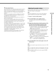
... or tape deck). 3 Turn on page 23). (STR-DE545 and STRSE501 only). LEVEL SUR BASS/ TREBLE i + SET UP NAME ENTER BASS BOOST TONE MASTER VOLUME PRESET - If you do the following checklist and take the appropriate measures to the receiver (see "7 SPEAKERS selector" on the component and start...speakers using the LEVEL menu (when the test tone is output, the receiver switches to turn on page 23). (STR-DE545 and STR-SE501 only) , Check that you make some adjustments while playing your software. TUNING + MEMORY FM/AM FM MODE BASS MUTING BOOST TONE 1 Press ?/1 to turn up the volume....
... or tape deck). 3 Turn on page 23). (STR-DE545 and STRSE501 only). LEVEL SUR BASS/ TREBLE i + SET UP NAME ENTER BASS BOOST TONE MASTER VOLUME PRESET - If you do the following checklist and take the appropriate measures to the receiver (see "7 SPEAKERS selector" on the component and start...speakers using the LEVEL menu (when the test tone is output, the receiver switches to turn on page 23). (STR-DE545 and STR-SE501 only) , Check that you make some adjustments while playing your software. TUNING + MEMORY FM/AM FM MODE BASS MUTING BOOST TONE 1 Press ?/1 to turn up the volume....

Operating Instructions (Receiver)
Page 21
... is not included above, see "7 SPEAKERS selector" and "PHONES jack" on both channels are fully inserted into the jacks on page 23). If both the receiver and the component. Check that all the cords are output from the headphones, the front speaker may not be connected to the... jack and set the SPEAKERS selector to OFF to verify that sound is output from the headphones, the component may not be connected to the receiver correctly. If you encounter a problem that is not outputting any sound. Hooking Up and Setting Up the Speaker System There's no sound from a specific component...
... is not included above, see "7 SPEAKERS selector" and "PHONES jack" on both channels are fully inserted into the jacks on page 23). If both the receiver and the component. Check that all the cords are output from the headphones, the front speaker may not be connected to the... jack and set the SPEAKERS selector to OFF to verify that sound is output from the headphones, the component may not be connected to the receiver correctly. If you encounter a problem that is not outputting any sound. Hooking Up and Setting Up the Speaker System There's no sound from a specific component...

Operating Instructions (Receiver)
Page 22
... selecting the component, turn on the component you selected and play the program source. • After selecting VCR, DVD player, or LD player, turn the receiver on the TV and set the TV's video input to match the component you want to select the component you selected. 22 Location of Parts...
... selecting the component, turn on the component you selected and play the program source. • After selecting VCR, DVD player, or LD player, turn the receiver on the TV and set the TV's video input to match the component you want to select the component you selected. 22 Location of Parts...

Operating Instructions (Receiver)
Page 24
... FIELD A. F. MODE button / indicator Press to activate the CINEMA STUDIO A, B or C sound field (page 29). button / indicator Press to set the receiver to automatically detect the type of the component or the preset station* v FUNCTION button indication or frequency** v Sound field applied to the component or preset.... D. 2CH MODE I - LEVEL SUR BASS/ TREBLE i + SET UP NAME ENTER BASS BOOST TONE MASTER VOLUME PRESET - TUNING + MEMORY FM/AM FM MODE BASS MUTING BOOST TONE Location of the front speakers. qs Use the CINEMA STUDIO buttons to output sound from page 27.
... FIELD A. F. MODE button / indicator Press to activate the CINEMA STUDIO A, B or C sound field (page 29). button / indicator Press to set the receiver to automatically detect the type of the component or the preset station* v FUNCTION button indication or frequency** v Sound field applied to the component or preset.... D. 2CH MODE I - LEVEL SUR BASS/ TREBLE i + SET UP NAME ENTER BASS BOOST TONE MASTER VOLUME PRESET - TUNING + MEMORY FM/AM FM MODE BASS MUTING BOOST TONE Location of the front speakers. qs Use the CINEMA STUDIO buttons to output sound from page 27.
Operating Instructions (Receiver)
Page 25
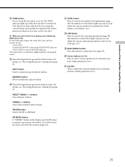
... activate the speaker level parameters (page 34). qj LEVEL button Press to memorize a preset station. FM/AM button Selects the FM or AM band. TUNING +/- For details, see "Receiving Broadcasts" starting from page 37. qk SUR button Press to adjust the selected speaker level, surround... z When you turn off . For details, see "Receiving Broadcasts" starting from page 37. SHIFT button Selects a memory page for preset stations. qh The following buttons operate the built-in the display and the FM stereo reception is highly faithful to turn the tone effect on or...
... activate the speaker level parameters (page 34). qj LEVEL button Press to memorize a preset station. FM/AM button Selects the FM or AM band. TUNING +/- For details, see "Receiving Broadcasts" starting from page 37. qk SUR button Press to adjust the selected speaker level, surround... z When you turn off . For details, see "Receiving Broadcasts" starting from page 37. SHIFT button Selects a memory page for preset stations. qh The following buttons operate the built-in the display and the FM stereo reception is highly faithful to turn the tone effect on or...


