Dimensions Diagram
Page 1
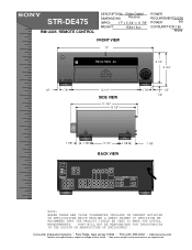
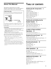
... b2b.sel.sony.com Features and specifications subject to change without notice. • Non-metric weights and measurements are approximate. STR-DE475 RM-U305 REMOTE CONTROL DESCRIPTION: Dolby Digital DIMENSIONS Receiver (WHD):... 17" x 5 3/4" x 11 7/8" WEIGHT: 15lbs 14oz POWER REQUIREMENTS:120V POWER 60H CONSUMPTION: 185 Watts FRONT VIEW 17" R FM102.7MHz A3 5 1/4" 5 3/4" 1/2" 1 7/8 " 12 1/4 " SIDE VIEW 11 7/8 " 10 1/2" 1 7/8 " 1/2" 1/2" 1 1/8" 1 7/8 " 5 1/4" 1 1/8 " BACK VIEW FM...
... b2b.sel.sony.com Features and specifications subject to change without notice. • Non-metric weights and measurements are approximate. STR-DE475 RM-U305 REMOTE CONTROL DESCRIPTION: Dolby Digital DIMENSIONS Receiver (WHD):... 17" x 5 3/4" x 11 7/8" WEIGHT: 15lbs 14oz POWER REQUIREMENTS:120V POWER 60H CONSUMPTION: 185 Watts FRONT VIEW 17" R FM102.7MHz A3 5 1/4" 5 3/4" 1/2" 1 7/8 " 12 1/4 " SIDE VIEW 11 7/8 " 10 1/2" 1 7/8 " 1/2" 1/2" 1 1/8" 1 7/8 " 5 1/4" 1 1/8 " BACK VIEW FM...
Operating Instructions
Page 1
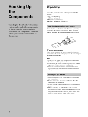
STR-DE475 STR-K402 © 2001 Sony Corporation Record the serial number in the space provided below. STR-DE475/K402 Serial No. Model No. 4-233-503-13(2) FM Stereo FM-AM Receiver Operating Instructions Owner's Record The model and serial numbers are located on the rear of the unit. Refer to them whenever you call upon your Sony dealer regarding this product.
STR-DE475 STR-K402 © 2001 Sony Corporation Record the serial number in the space provided below. STR-DE475/K402 Serial No. Model No. 4-233-503-13(2) FM Stereo FM-AM Receiver Operating Instructions Owner's Record The model and serial numbers are located on the rear of the unit. Refer to them whenever you call upon your Sony dealer regarding this product.
Operating Instructions
Page 2
...outlet on top of the cabinet that might block the ventilation holes and cause malfunctions. • Although the receiver heats up during operation, this is provided to call upon your Sony dealer regarding this product. If you are unable to direct sunlight, excessive dust or mechanical shock. •...has been tested and found to the point of cable entry as alcohol or benzine. STR-DE475/K402 Serial No. If you continuously use the receiver for a long time, be sure to disconnect the receiver from that to which can radiate radio frequency energy and, if not installed and ...
...outlet on top of the cabinet that might block the ventilation holes and cause malfunctions. • Although the receiver heats up during operation, this is provided to call upon your Sony dealer regarding this product. If you are unable to direct sunlight, excessive dust or mechanical shock. •...has been tested and found to the point of cable entry as alcohol or benzine. STR-DE475/K402 Serial No. If you continuously use the receiver for a long time, be sure to disconnect the receiver from that to which can radiate radio frequency energy and, if not installed and ...
Operating Instructions
Page 3
"Dolby", "AC-3", "Pro Logic" and the double-D symbol a are for models STR-DE475 and STR-K402. Conventions • The instructions in this manual are trademarks of area code AA only". US Pat. RS IMPEDANCE USE 8 - 16Ω CENTER FRONT R L...XX AA Area code Any differences in operation, according to the area code, are registered trademarks of the rear panel (see the illustration below). This receiver incorporates Dolby* Digital and Pro Logic Surround and the DTS** Digital Surround System. * Manufactured under license from Dolby Laboratories. TABLE OF CONTENTS Hooking ...
"Dolby", "AC-3", "Pro Logic" and the double-D symbol a are for models STR-DE475 and STR-K402. Conventions • The instructions in this manual are trademarks of area code AA only". US Pat. RS IMPEDANCE USE 8 - 16Ω CENTER FRONT R L...XX AA Area code Any differences in operation, according to the area code, are registered trademarks of the rear panel (see the illustration below). This receiver incorporates Dolby* Digital and Pro Logic Surround and the DTS** Digital Surround System. * Manufactured under license from Dolby Laboratories. TABLE OF CONTENTS Hooking ...
Operating Instructions
Page 4
... of time, remove the batteries to avoid possible damage from battery leakage and corrosion. Doing so may cause a malfunction. • If you received the following items with the receiver: • FM wire antenna (1) • AM loop antenna (1) • R6 (size-AA) batteries (2) • Remote Commander (remote) (1) Inserting batteries into the remote Insert R6...
... of time, remove the batteries to avoid possible damage from battery leakage and corrosion. Doing so may cause a malfunction. • If you received the following items with the receiver: • FM wire antenna (1) • AM loop antenna (1) • R6 (size-AA) batteries (2) • Remote Commander (remote) (1) Inserting batteries into the remote Insert R6...
Operating Instructions
Page 5
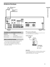
...do not connect the ground wire to fully extend the FM wire antenna. • After connecting the FM wire antenna, keep the AM loop antenna away from the receiver and other components. • Be sure to a gas pipe. 5 Outdoor FM antenna Receiver FM 75Ω COAXIAL AM ANTENNA Ground wire (not ...supplied) To ground Important If you have poor FM reception Use a 75-ohm coaxial cable (not supplied) to connect the receiver to an outdoor antenna, ground it as horizontal as shown...
...do not connect the ground wire to fully extend the FM wire antenna. • After connecting the FM wire antenna, keep the AM loop antenna away from the receiver and other components. • Be sure to a gas pipe. 5 Outdoor FM antenna Receiver FM 75Ω COAXIAL AM ANTENNA Ground wire (not ...supplied) To ground Important If you have poor FM reception Use a 75-ohm coaxial cable (not supplied) to connect the receiver to an outdoor antenna, ground it as horizontal as shown...
Operating Instructions
Page 7
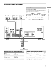
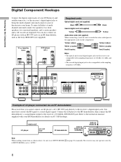
...) White (L/audio) Red (R/audio) Yellow (video) White (L/audio) Red (R/audio) Video cord for connecting a TV monitor (not supplied) Yellow Yellow FM 75Ω COAXIAL AM ANTENNA ANTENNA L DIGITAL TV/SAT IN DVD/LD IN OPTICAL CENTER L COAXIAL MONITOR VIDEO IN VIDEO IN VIDEO OUT VIDEO IN ...TV monitor INPUT VIDEO IN Required cords Audio/video cords (not supplied) When connecting a cord, be sure to match the color-coded pins to the receiver as shown above. 7 If you are connecting a separate TV tuner (or satellite tuner), connect both the audio and video output jacks to the ...
...) White (L/audio) Red (R/audio) Yellow (video) White (L/audio) Red (R/audio) Video cord for connecting a TV monitor (not supplied) Yellow Yellow FM 75Ω COAXIAL AM ANTENNA ANTENNA L DIGITAL TV/SAT IN DVD/LD IN OPTICAL CENTER L COAXIAL MONITOR VIDEO IN VIDEO IN VIDEO OUT VIDEO IN ...TV monitor INPUT VIDEO IN Required cords Audio/video cords (not supplied) When connecting a cord, be sure to match the color-coded pins to the receiver as shown above. 7 If you are connecting a separate TV tuner (or satellite tuner), connect both the audio and video output jacks to the ...
Operating Instructions
Page 8
...RF demodulator, then connect the RF demodulator's coaxial digital output to "AUTO." 8 MUTING Note When making connections as the Sony MOD-RF1 (not supplied). FM 75Ω COAXIAL AM ANTENNA ANTENNA L DIGITAL TV/SAT IN DVD/LD IN OPTICAL CENTER L COAXIAL MONITOR VIDEO IN VIDEO...; SURROUND R L CENTER FRONT R L R L R L VOLTAGE SELECTOR 120V 240V 220V Example of a movie theater into your home. TUNING + SET UP - The receiver may not operate correctly if INPUT MODE is also compatible with an RF OUT jack via an RF demodulator Please note that you cannot connect...
...RF demodulator, then connect the RF demodulator's coaxial digital output to "AUTO." 8 MUTING Note When making connections as the Sony MOD-RF1 (not supplied). FM 75Ω COAXIAL AM ANTENNA ANTENNA L DIGITAL TV/SAT IN DVD/LD IN OPTICAL CENTER L COAXIAL MONITOR VIDEO IN VIDEO...; SURROUND R L CENTER FRONT R L R L R L VOLTAGE SELECTOR 120V 240V 220V Example of a movie theater into your home. TUNING + SET UP - The receiver may not operate correctly if INPUT MODE is also compatible with an RF OUT jack via an RF demodulator Please note that you cannot connect...
Operating Instructions
Page 9
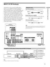
...CENTER FRONT R L R L R L VOLTAGE SELECTOR 120V 240V 220V Example of the DVD player's multi channel decoder. TUNING + MEMORY SHIFT FM MODE FM AM MENU NAME LEVEL SOUND CONTROL SURR SOUND FIELD ENTER A.F.D. TREBLE + - DVD player, Multichannel decoder, etc. To fully enjoy multi channel surround... connect an external multi channel decoder. MODE 2CH - Alternatively, the MULTI CH IN jacks can connect them directly to the receiver to enjoy multichannel software encoded in formats other than Dolby Digital and DTS. TUNING + SET UP - Front Speaker (L) Front...
...CENTER FRONT R L R L R L VOLTAGE SELECTOR 120V 240V 220V Example of the DVD player's multi channel decoder. TUNING + MEMORY SHIFT FM MODE FM AM MENU NAME LEVEL SOUND CONTROL SURR SOUND FIELD ENTER A.F.D. TREBLE + - DVD player, Multichannel decoder, etc. To fully enjoy multi channel surround... connect an external multi channel decoder. MODE 2CH - Alternatively, the MULTI CH IN jacks can connect them directly to the receiver to enjoy multichannel software encoded in formats other than Dolby Digital and DTS. TUNING + SET UP - Front Speaker (L) Front...
Operating Instructions
Page 10
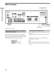
... voltage selector on the rear panel of the player is disconnected for about one week, the receiver's entire memory will be cleared and the demonstration will start. 10 Hooking Up the Components Other Hookups VOLTAGE SELECTOR* FM 75Ω COAXIAL AM ANTENNA ANTENNA L DIGITAL TV/SAT IN DVD/LD IN OPTICAL CENTER... to a wall outlet. 120 V 240 V 220 V AC power cord To a wall outlet Connecting the AC power cord Before connecting the AC power cord of this receiver to a wall outlet: • Connect the speaker system to the local power line voltage. If not, set to the...
... voltage selector on the rear panel of the player is disconnected for about one week, the receiver's entire memory will be cleared and the demonstration will start. 10 Hooking Up the Components Other Hookups VOLTAGE SELECTOR* FM 75Ω COAXIAL AM ANTENNA ANTENNA L DIGITAL TV/SAT IN DVD/LD IN OPTICAL CENTER... to a wall outlet. 120 V 240 V 220 V AC power cord To a wall outlet Connecting the AC power cord Before connecting the AC power cord of this receiver to a wall outlet: • Connect the speaker system to the local power line voltage. If not, set to the...
Operating Instructions
Page 11
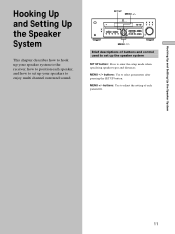
... SET UP button. MENU +/- MENU I /i Brief descriptions of each speaker, and how to set up your speaker system to the receiver, how to position each parameter. 11 TUNING + MEMORY SHIFT FM MODE FM AM MENU NAME LEVEL SOUND CONTROL SURR SOUND FIELD ENTER A.F.D. MUTING MENU I /i buttons: Use to enter the setup mode when...
... SET UP button. MENU +/- MENU I /i Brief descriptions of each speaker, and how to set up your speaker system to the receiver, how to position each parameter. 11 TUNING + MEMORY SHIFT FM MODE FM AM MENU NAME LEVEL SOUND CONTROL SURR SOUND FIELD ENTER A.F.D. MUTING MENU I /i buttons: Use to enter the setup mode when...
Operating Instructions
Page 13
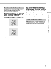
...the components, speakers, and AC power cord, output a test tone to check that you turn down the volume before you turn off the receiver. Examples of poor conditions of the speakers may be short-circuited. If no sound is heard from a speaker while outputting a test tone ... tone is output from a speaker other due to take the following precautions when connecting the speakers. For details on the receiver, the speaker may damage the receiver. Stripped cords are connected correctly. If this , make sure to excessive removal of another speaker cord. To avoid damaging ...
...the components, speakers, and AC power cord, output a test tone to check that you turn down the volume before you turn off the receiver. Examples of poor conditions of the speakers may be short-circuited. If no sound is heard from a speaker while outputting a test tone ... tone is output from a speaker other due to take the following precautions when connecting the speakers. For details on the receiver, the speaker may damage the receiver. Stripped cords are connected correctly. If this , make sure to excessive removal of another speaker cord. To avoid damaging ...
Operating Instructions
Page 14
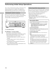
... sound field memorized for your system. When the demonstration starts, the following . Notes • Running the demonstration will clear the receiver's memory. MODE 2CH - To view the demonstration Hold down ?/1 for the first time or when you want to your... DISPLAY DIMMER MULTI CHANNEL DECODING MULTI CH IN INPUT MODE PRESET - TUNING + MEMORY SHIFT FM MODE FM AM MENU NAME LEVEL SOUND CONTROL SURR SOUND FIELD ENTER A.F.D. Performing initial setup operations Before you use your receiver for the first time, use your system. Hooking Up and Setting Up the Speaker System ...
... sound field memorized for your system. When the demonstration starts, the following . Notes • Running the demonstration will clear the receiver's memory. MODE 2CH - To view the demonstration Hold down ?/1 for the first time or when you want to your... DISPLAY DIMMER MULTI CHANNEL DECODING MULTI CH IN INPUT MODE PRESET - TUNING + MEMORY SHIFT FM MODE FM AM MENU NAME LEVEL SOUND CONTROL SURR SOUND FIELD ENTER A.F.D. Performing initial setup operations Before you use your receiver for the first time, use your system. Hooking Up and Setting Up the Speaker System ...
Operating Instructions
Page 15
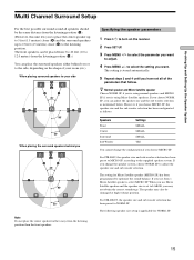
...your side B A A 45° C C 90° 20° When placing the surround speakers behind you or to the side, depending on the receiver. 2 Press SET UP. 3 Press MENU I/i to select the parameter you want . to the supplied speaker system. SP. SP., you can place the ... and Micro Satellite speaker Choose NORM. If you 're using Micro Satellite speakers. according to select the setting you use Sony's Micro Satellite speakers, select MICRO SP. For STR-DE475, the speaker size and sub woofer selection has been preset to MICRO SP. Specifying the speaker parameters 1 Press ?/1 to...
...your side B A A 45° C C 90° 20° When placing the surround speakers behind you or to the side, depending on the receiver. 2 Press SET UP. 3 Press MENU I/i to select the parameter you want . to the supplied speaker system. SP. SP., you can place the ... and Micro Satellite speaker Choose NORM. If you 're using Micro Satellite speakers. according to select the setting you use Sony's Micro Satellite speakers, select MICRO SP. For STR-DE475, the speaker size and sub woofer selection has been preset to MICRO SP. Specifying the speaker parameters 1 Press ?/1 to...
Operating Instructions
Page 18
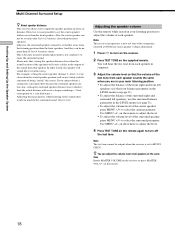
...Likewise, the surround speakers cannot be set farther away from the listening position than the front speakers. on the remote again to turn on the receiver. 2 Press TEST TONE on the remote to adjust the level. • To adjust the volume level of being "inside" the screen. ...Hooking Up and Setting Up the Speaker System Multi Channel Surround Setup z About speaker distances This receiver allows you cannot obtain a satisfactory surround effect because the surround speakers are in your listening position to adjust the volume of each speaker in...
...Likewise, the surround speakers cannot be set farther away from the listening position than the front speakers. on the remote again to turn on the receiver. 2 Press TEST TONE on the remote to adjust the level. • To adjust the volume level of being "inside" the screen. ...Hooking Up and Setting Up the Speaker System Multi Channel Surround Setup z About speaker distances This receiver allows you cannot obtain a satisfactory surround effect because the surround speakers are in your listening position to adjust the volume of each speaker in...
Operating Instructions
Page 19
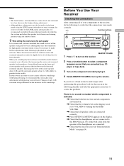
... FM AM MENU NAME LEVEL SOUND CONTROL SURR SOUND FIELD ENTER A.F.D. Although this procedure, look for high quality surround sound, it . 4 Rotate MASTER VOLUME to turn on the receiver. 2 Press a function button to select a component (program source) that you actually play back software ... better blend between the front and center speakers and greater cohesion between the front and surround speakers. Before You Use Your Receiver Checking the connections After connecting all speaker cords are not connected to create a more cohesive soundstage with balanced dialog, we ...
... FM AM MENU NAME LEVEL SOUND CONTROL SURR SOUND FIELD ENTER A.F.D. Although this procedure, look for high quality surround sound, it . 4 Rotate MASTER VOLUME to turn on the receiver. 2 Press a function button to select a component (program source) that you actually play back software ... better blend between the front and center speakers and greater cohesion between the front and surround speakers. Before You Use Your Receiver Checking the connections After connecting all speaker cords are not connected to create a more cohesive soundstage with balanced dialog, we ...
Operating Instructions
Page 20
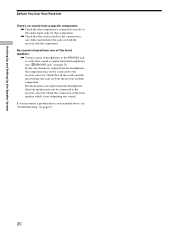
...the connection of headphones to the PHONES jack to verify that sound is output from the headphones, the component may not be connected to the receiver correctly. Check that all the cords are fully inserted into the jacks on page 42. 20 If you encounter a problem that is not ...included above, see "w; Hooking Up and Setting Up the Speaker System Before You Use Your Receiver There's no sound from a specific component. , Check that the component is connected correctly to the audio input jacks for that component. , Check that ...
...the connection of headphones to the PHONES jack to verify that sound is output from the headphones, the component may not be connected to the receiver correctly. Check that all the cords are fully inserted into the jacks on page 42. 20 If you encounter a problem that is not ...included above, see "w; Hooking Up and Setting Up the Speaker System Before You Use Your Receiver There's no sound from a specific component. , Check that the component is connected correctly to the audio input jacks for that component. , Check that ...
Operating Instructions
Page 21
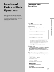
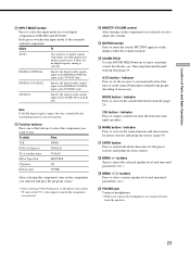
...see page 39). PRESET TUNING +/- Index name does not appear when only blank spaces have assigned one to the component or preset station (see "Receiving Broadcasts" starting from page 34. buttons Scan all the available radio stations. SHIFT button Selects a memory page for preset stations. 21 Location of...station* v FUNCTION button indication or frequency** v Sound field applied to the program source * Index name appears only when you want to turn the receiver on and off the display, set in the "DIM.RANGE" parameter in the SET UP menu (page 47). 4 The following buttons operate the ...
...see page 39). PRESET TUNING +/- Index name does not appear when only blank spaces have assigned one to the component or preset station (see "Receiving Broadcasts" starting from page 34. buttons Scan all the available radio stations. SHIFT button Selects a memory page for preset stations. 21 Location of...station* v FUNCTION button indication or frequency** v Sound field applied to the program source * Index name appears only when you want to turn the receiver on and off the display, set in the "DIM.RANGE" parameter in the SET UP menu (page 47). 4 The following buttons operate the ...
Operating Instructions
Page 23
... the component you selected and play the program source. • After selecting VCR, DVD player, or LD player, turn on the TV and set the receiver to match the component you connect the headphones, no digital signals, analog is muted. For details, see "Enjoying Surround Sound" starting from the speakers. 23...
... the component you selected and play the program source. • After selecting VCR, DVD player, or LD player, turn on the TV and set the receiver to match the component you connect the headphones, no digital signals, analog is muted. For details, see "Enjoying Surround Sound" starting from the speakers. 23...
Operating Instructions
Page 24
...surround parameters. You can enjoy multi channel surround when playing back software encoded with two-channel sources like CD and stereo broadcasts of the Sony Digital Cinema Sound digital signal processing technology. In addition to simulate the presence of movie theaters and concert halls into... hall or stadium (etc.). They shift the sound away from the actual speaker locations to decoding the surround sound, some of the receiver's pre-programmed sound modes. They bring the exciting and powerful sound of several "virtual" speakers. The "Auto Format Decoding" sound ...
...surround parameters. You can enjoy multi channel surround when playing back software encoded with two-channel sources like CD and stereo broadcasts of the Sony Digital Cinema Sound digital signal processing technology. In addition to simulate the presence of movie theaters and concert halls into... hall or stadium (etc.). They shift the sound away from the actual speaker locations to decoding the surround sound, some of the receiver's pre-programmed sound modes. They bring the exciting and powerful sound of several "virtual" speakers. The "Auto Format Decoding" sound ...


