Service Manual
Page 3
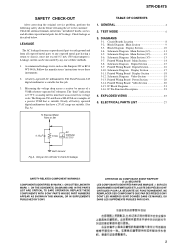
STR-DE475 SAFETY CHECK-OUT After correcting the original service...instructions to check AC leakage. A) To Exposed Metal Parts on Set TABLE OF CONTENTS 1. TEST MODE 6 3. Schematic Diagram Main Section (3/3 13 3-7. Printed Wiring Board Power Section 20 3-14. IC Pin Function Description 23 4. Using an...OR IN SUPPLEMENTS PUBLISHED BY SONY. A commercial leakage tester, such as described below. DIAGRAMS 3-1. Block Diagram Display Section 10 3-4. Printed Wiring Board Digital Section 16 3-10. Schematic Diagram Display Section 17 3-11. IC Block Diagrams 21 3-16. EXPLODED VIEWS...
STR-DE475 SAFETY CHECK-OUT After correcting the original service...instructions to check AC leakage. A) To Exposed Metal Parts on Set TABLE OF CONTENTS 1. TEST MODE 6 3. Schematic Diagram Main Section (3/3 13 3-7. Printed Wiring Board Power Section 20 3-14. IC Pin Function Description 23 4. Using an...OR IN SUPPLEMENTS PUBLISHED BY SONY. A commercial leakage tester, such as described below. DIAGRAMS 3-1. Block Diagram Display Section 10 3-4. Printed Wiring Board Digital Section 16 3-10. Schematic Diagram Display Section 17 3-11. IC Block Diagrams 21 3-16. EXPLODED VIEWS...
Service Manual
Page 7
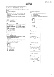
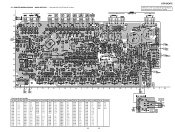
...8226; A : B+ Line. • B : B- No mark : FM • Voltages are taken with mark ! MAIN BOARD - 1 IC301 qf 230ns 2.2Vp-p - SECTION 3 DIAGRAMS STR-DE475 THIS NOTE IS COMMON FOR PRINTED WIRING BOARDS AND SCHEMATIC DIAGRAMS. (In addition to this necessary note is printed in each block.) For... schematic diagrams. Note: • All capacitors are in Ω and 1/4 W or ...
...8226; A : B+ Line. • B : B- No mark : FM • Voltages are taken with mark ! MAIN BOARD - 1 IC301 qf 230ns 2.2Vp-p - SECTION 3 DIAGRAMS STR-DE475 THIS NOTE IS COMMON FOR PRINTED WIRING BOARDS AND SCHEMATIC DIAGRAMS. (In addition to this necessary note is printed in each block.) For... schematic diagrams. Note: • All capacitors are in Ω and 1/4 W or ...
Service Manual
Page 10
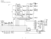
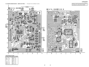
DISPLAY SECTION - • R-CH is omitted due to same as L-CH. • Signal Path : FM L SL A C SW FL101 FLUORESCENT INDICATOR TUBE FL1 FL2 14 29 42 31 SEG1-16 GRID1-12 STB CLK DIN 789... RELAY DRIVE Q560 RY560 J253 SUB WOOFER AUDIO OUT 58 15 10 14 12 13 55 HP SW SIRCS 57 IC101 REMOTE 1 CONTROL 2 RECEIVER D109 VCC 23 VCC 84 RESET 77 HSTX 52 STOP 47 8 D101 B RESET D110 RESET Q100,101 POWER RY POWER AMP -B FL201 ...3 POWER 8 CONTROL 5 IC950 6 D910-913 D914 T902 D915 RELAY DRIVE Q901 RY901 E MODEL VOLTAGE SELECTOR S901 AC IN 10 10 BLOCK DIAGRAM - STR-DE475 3-3.
DISPLAY SECTION - • R-CH is omitted due to same as L-CH. • Signal Path : FM L SL A C SW FL101 FLUORESCENT INDICATOR TUBE FL1 FL2 14 29 42 31 SEG1-16 GRID1-12 STB CLK DIN 789... RELAY DRIVE Q560 RY560 J253 SUB WOOFER AUDIO OUT 58 15 10 14 12 13 55 HP SW SIRCS 57 IC101 REMOTE 1 CONTROL 2 RECEIVER D109 VCC 23 VCC 84 RESET 77 HSTX 52 STOP 47 8 D101 B RESET D110 RESET Q100,101 POWER RY POWER AMP -B FL201 ...3 POWER 8 CONTROL 5 IC950 6 D910-913 D914 T902 D915 RELAY DRIVE Q901 RY901 E MODEL VOLTAGE SELECTOR S901 AC IN 10 10 BLOCK DIAGRAM - STR-DE475 3-3.
Service Manual
Page 14
... 14 14 IC 807 IC 806 IC 804 (Page 20) (Page 16) (Page 20) (Page 20) (Page 18) (Page 18) PHONES 3-7. STR-DE475 There are a few cases that the part printed on this diagram isn't mounted in this model. Location Ref. Location Ref. No. No. No. PRINTED WIRING BOARD - Location Ref. Location Ref.
... 14 14 IC 807 IC 806 IC 804 (Page 20) (Page 16) (Page 20) (Page 20) (Page 18) (Page 18) PHONES 3-7. STR-DE475 There are a few cases that the part printed on this diagram isn't mounted in this model. Location Ref. Location Ref. No. No. No. PRINTED WIRING BOARD - Location Ref. Location Ref.
Service Manual
Page 16
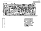
... SECTION - • See page 8 for Circuit Boards Location. Location Ref. 3-9. DIGITAL (Page 18) IC 1002 IC 1010 IC 1009 IC 1013 (Page 14) IC 1003 STR-DE475 There are a few cases that the part printed on this diagram isn't mounted in this model.
... SECTION - • See page 8 for Circuit Boards Location. Location Ref. 3-9. DIGITAL (Page 18) IC 1002 IC 1010 IC 1009 IC 1013 (Page 14) IC 1003 STR-DE475 There are a few cases that the part printed on this diagram isn't mounted in this model.
Service Manual
Page 18
... D-9 D011 A-9 D014 B-5 D100 C-12 D101 A-6 D102 A-8 D103 C-6 D109 B-12 D110 B-12 IC101 B-13 IC102 B-7 IC103 B-10 Q008 D-12 Q009 C-5 Q100 A-8 Q101 A-7 Q103 D-3 Q104 D-3 18 18 STR-DE475 There are a few cases that the part printed on this diagram isn't mounted in this model. (Page 20) (Page 14) IC 101 (Page 14) 3-11. No.
... D-9 D011 A-9 D014 B-5 D100 C-12 D101 A-6 D102 A-8 D103 C-6 D109 B-12 D110 B-12 IC101 B-13 IC102 B-7 IC103 B-10 Q008 D-12 Q009 C-5 Q100 A-8 Q101 A-7 Q103 D-3 Q104 D-3 18 18 STR-DE475 There are a few cases that the part printed on this diagram isn't mounted in this model. (Page 20) (Page 14) IC 101 (Page 14) 3-11. No.
Service Manual
Page 20
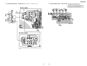
PRINTED WIRING BOARD - PRINTED WIRING BOARD - There are a few cases that the part printed on this diagram isn't mounted in this model. 3-13. VIDEO SECTION -• See page 8 for Circuit Boards Location. • See page 20 for Circuit Boards Location. (Page 14) (Page 14) IC 950 (Page 18) STR-DE475 3-14. POWER SECTION -• See page 8 for Schematic Diagram. IC 1015 IC 1014 (Page 18) (Page 14) E model only 1-680-431- 20 20
PRINTED WIRING BOARD - PRINTED WIRING BOARD - There are a few cases that the part printed on this diagram isn't mounted in this model. 3-13. VIDEO SECTION -• See page 8 for Circuit Boards Location. • See page 20 for Circuit Boards Location. (Page 14) (Page 14) IC 950 (Page 18) STR-DE475 3-14. POWER SECTION -• See page 8 for Schematic Diagram. IC 1015 IC 1014 (Page 18) (Page 14) E model only 1-680-431- 20 20
Service Manual
Page 27
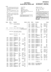
...PD... Ref. Part No. Some delay should be different from the original one. • Items marked "*" are not stocked since they are in the diagrams or the components used on the set. • -XX, -X mean standardized parts, so they may be anticipated when ordering these items. • ...-11 PIN, CONNECTOR 12P * CNP502 1-564-506-11 PLUG, CONNECTOR 3P CNS103 1-794-006-11 CONNECTOR 20P 27 SECTION 5 ELECTRICAL PARTS LIST STR-DE475 AC SELECT DIGITAL NOTE: • Due to standardization, replacements in the parts list may have some difference from the parts specified in ohms. METAL...
...PD... Ref. Part No. Some delay should be different from the original one. • Items marked "*" are not stocked since they are in the diagrams or the components used on the set. • -XX, -X mean standardized parts, so they may be anticipated when ordering these items. • ...-11 PIN, CONNECTOR 12P * CNP502 1-564-506-11 PLUG, CONNECTOR 3P CNS103 1-794-006-11 CONNECTOR 20P 27 SECTION 5 ELECTRICAL PARTS LIST STR-DE475 AC SELECT DIGITAL NOTE: • Due to standardization, replacements in the parts list may have some difference from the parts specified in ohms. METAL...
