
Limited Warranty (U.S. Only)
Page 1
... defects in material or workmanship as fuses or batteries). LABOR: For a period of two (2) year from your convenience, Sony Electronics Inc. PARTS: In addition, Sony will repair or replace the Product, at its original packaging or packaging affording an equal degree of purchase, if this Product... ANY EXPRESS OR IMPLIED WARRANTY ON THIS PRODUCT. 4-557-173-02 General Stereo/Hifi Components/Tape Decks ® CD Players/Mini Disc Players/Audio Systems Hifi Audio LIMITED WARRANTY Sony Electronics Inc. ("Sony") warrants this Product is determined to be presented to you must pay for...
... defects in material or workmanship as fuses or batteries). LABOR: For a period of two (2) year from your convenience, Sony Electronics Inc. PARTS: In addition, Sony will repair or replace the Product, at its original packaging or packaging affording an equal degree of purchase, if this Product... ANY EXPRESS OR IMPLIED WARRANTY ON THIS PRODUCT. 4-557-173-02 General Stereo/Hifi Components/Tape Decks ® CD Players/Mini Disc Players/Audio Systems Hifi Audio LIMITED WARRANTY Sony Electronics Inc. ("Sony") warrants this Product is determined to be presented to you must pay for...
Operating Instructions
Page 2
... and can be sure to call upon your Sony dealer regarding this product. Reorient or relocate the receiving antenna. - Note to CATV system installer: This reminder is provided to disconnect the receiver from that the operating voltage is connected. - STR-DE475/K402 Serial No. On safety • Should ...with the instructions, may be connected to turn off and unplug the receiver. Do not use any question or problem concerning your receiver, please consult your dealer. (for a Class B digital device, pursuant to Part 15 of cable entry as close to prevent heat buildup and prolong...
... and can be sure to call upon your Sony dealer regarding this product. Reorient or relocate the receiving antenna. - Note to CATV system installer: This reminder is provided to disconnect the receiver from that the operating voltage is connected. - STR-DE475/K402 Serial No. On safety • Should ...with the instructions, may be connected to turn off and unplug the receiver. Do not use any question or problem concerning your receiver, please consult your dealer. (for a Class B digital device, pursuant to Part 15 of cable entry as close to prevent heat buildup and prolong...
Operating Instructions
Page 3
... by looking at the lower right corner of Parts and Basic Operations 21 Front Panel Parts Descriptions 21 Enjoying Surround Sound 24 Selecting a Sound Field 25 Understanding the Multi-Channel Surround Displays 28 Customizing Sound Fields 30 Receiving Broadcasts 34 Direct Tuning 36 Automatic Tuning 36 ...the illustration below). About area codes The area code of the player you purchased is used in this manual: z Indicates hints and tips for models STR-DE475 and STR-K402. "Dolby", "AC-3", "Pro Logic" and the double-D symbol a are registered trademarks of area code AA only". No. 5,451,942,...
... by looking at the lower right corner of Parts and Basic Operations 21 Front Panel Parts Descriptions 21 Enjoying Surround Sound 24 Selecting a Sound Field 25 Understanding the Multi-Channel Surround Displays 28 Customizing Sound Fields 30 Receiving Broadcasts 34 Direct Tuning 36 Automatic Tuning 36 ...the illustration below). About area codes The area code of the player you purchased is used in this manual: z Indicates hints and tips for models STR-DE475 and STR-K402. "Dolby", "AC-3", "Pro Logic" and the double-D symbol a are registered trademarks of area code AA only". No. 5,451,942,...
Operating Instructions
Page 21
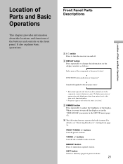
...you want to the component or preset station (see "Receiving Broadcasts" starting from page 34. buttons Scan all preset stations. Location of Parts and Basic Operations This chapter provides information about the locations and functions of Parts and Basic Operations Index name does not appear when ...only blank spaces have assigned one to turn the receiver on the front panel. For details, see page 39). When you have been ...
...you want to the component or preset station (see "Receiving Broadcasts" starting from page 34. buttons Scan all preset stations. Location of Parts and Basic Operations This chapter provides information about the locations and functions of Parts and Basic Operations Index name does not appear when ...only blank spaces have assigned one to turn the receiver on the front panel. For details, see page 39). When you have been ...
Operating Instructions
Page 22
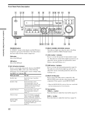
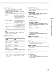
Front Panel Parts Description 1 23 4 5 6 7 89 0 qa qs ? / 1 PHONES DISPLAY DIMMER MULTI CHANNEL DECODING MULTI CH IN INPUT MODE PRESET - TUNING + MEMORY SHIFT FM MODE FM AM MENU NAME LEVEL SOUND CONTROL SURR SOUND FIELD ENTER A.F.D. ql qk qj qh qg qf qd FM MODE button If "STEREO" flashes in a Multi Channel ...MULTI CH IN. • When the MULTI CH IN is decoding signals recorded in the display and the FM stereo reception is improved. You will not have the stereo effect but the sound is poor, press this button. The indicator on the button lights up when the ...
Front Panel Parts Description 1 23 4 5 6 7 89 0 qa qs ? / 1 PHONES DISPLAY DIMMER MULTI CHANNEL DECODING MULTI CH IN INPUT MODE PRESET - TUNING + MEMORY SHIFT FM MODE FM AM MENU NAME LEVEL SOUND CONTROL SURR SOUND FIELD ENTER A.F.D. ql qk qj qh qg qf qd FM MODE button If "STEREO" flashes in a Multi Channel ...MULTI CH IN. • When the MULTI CH IN is decoding signals recorded in the display and the FM stereo reception is improved. You will not have the stereo effect but the sound is poor, press this button. The indicator on the button lights up when the ...
Operating Instructions
Page 23
...to set the TV's video input to adjust the volume. qk MENU +/- qd MASTER VOLUME control After turning on the TV and set the receiver to mute the sound. MODE button / indicator Press to activate the sound field selection mode (page 25). 2CH button / indicator Press to...(DVD/LD only) ANALOG Specify the analog audio signals input to digital signals when there are both digital and analog connections. Location of Parts and Basic Operations qa INPUT MODE button Press to use. qs Function buttons Press one of the currently selected component. PHONES jack Connects headphones...
...to set the TV's video input to adjust the volume. qk MENU +/- qd MASTER VOLUME control After turning on the TV and set the receiver to mute the sound. MODE button / indicator Press to activate the sound field selection mode (page 25). 2CH button / indicator Press to...(DVD/LD only) ANALOG Specify the analog audio signals input to digital signals when there are both digital and analog connections. Location of Parts and Basic Operations qa INPUT MODE button Press to use. qs Function buttons Press one of the currently selected component. PHONES jack Connects headphones...
Operating Instructions
Page 45
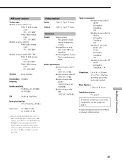
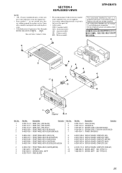
... 340 W In Standby Condition: 1 W Dimensions 430 × 145 × 298 mm (17 × 5 6/8 × 116/8 in any AM station, turn off the receiver. After tuning in .) including projecting parts and controls Mass (Approx.) 7.2 kg (15 lb 14 oz) Supplied accessories See page 4. To reset the scale to 9 kHz y 10 kHz. Design and...
... 340 W In Standby Condition: 1 W Dimensions 430 × 145 × 298 mm (17 × 5 6/8 × 116/8 in any AM station, turn off the receiver. After tuning in .) including projecting parts and controls Mass (Approx.) 7.2 kg (15 lb 14 oz) Supplied accessories See page 4. To reset the scale to 9 kHz y 10 kHz. Design and...
Service Manual
Page 2
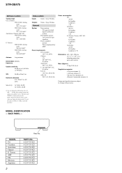
...Supplied accessories • FM wire antenna (1) • AM loop antenna (1) • R6 (size-AA) batteries (2) • Remote Commander (remote) (1) Design and specifications are subject to change without notice. PARTS No. 4-233-753... UK Mexican Argentina 2 Parts No. All preset stations will be erased when you change the AM tuning scale to 10 kHz (or 9 kHz), repeat the procedure. STR-DE475 AM tuner section Tuning range...215; 7 7/8 × 19 5/8 in any AM station, turn off the receiver. BACK PANEL - Hold down the TUNING + button and press the button. MODEL IDENTIFICATION -
...Supplied accessories • FM wire antenna (1) • AM loop antenna (1) • R6 (size-AA) batteries (2) • Remote Commander (remote) (1) Design and specifications are subject to change without notice. PARTS No. 4-233-753... UK Mexican Argentina 2 Parts No. All preset stations will be erased when you change the AM tuning scale to 10 kHz (or 9 kHz), repeat the procedure. STR-DE475 AM tuner section Tuning range...215; 7 7/8 × 19 5/8 in any AM station, turn off the receiver. BACK PANEL - Hold down the TUNING + button and press the button. MODEL IDENTIFICATION -
Service Manual
Page 3
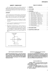
...Section 20 3-14. Using an AC voltmeter to use these instruments. 2. REPLACE THESE COMPONENTS WITH SONY PARTS WHOSE PART NUMBERS APPEAR AS SHOWN IN THIS MANUAL OR IN SUPPLEMENTS PUBLISHED BY SONY. Block Diagram Main Section 9 3-3. Printed Wiring Board Display Section 18 3-12. EXPLODED VIEWS 25... 10 3-4. GENERAL 4 2. STR-DE475 SAFETY CHECK-OUT After correcting the original service problem, perform the following safety checks before releasing the set to the customer: Check the antenna terminals, metal trim, "metallized" knobs, screws, and all other exposed metal parts for this job. 3. The...
...Section 20 3-14. Using an AC voltmeter to use these instruments. 2. REPLACE THESE COMPONENTS WITH SONY PARTS WHOSE PART NUMBERS APPEAR AS SHOWN IN THIS MANUAL OR IN SUPPLEMENTS PUBLISHED BY SONY. Block Diagram Main Section 9 3-3. Printed Wiring Board Display Section 18 3-12. EXPLODED VIEWS 25... 10 3-4. GENERAL 4 2. STR-DE475 SAFETY CHECK-OUT After correcting the original service problem, perform the following safety checks before releasing the set to the customer: Check the antenna terminals, metal trim, "metallized" knobs, screws, and all other exposed metal parts for this job. 3. The...
Service Manual
Page 7
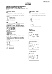
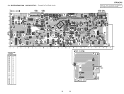
... : Through hole. • f : internal component. • b : Pattern from the side which enables seeing. or dotted line with part number specified. Replace only with mark ! Ne les remplacer que par une pièce portant le numéro spécifié.... model. • Waveform - No mark : FM • Voltages are taken with a oscilloscope. • Circled numbers refer to waveforms. • Signal path. sont critiques pour la sécurité. MAIN BOARD - 1 IC301 qf 230ns 2.2Vp-p - SECTION 3 DIAGRAMS STR-DE475 THIS NOTE IS COMMON FOR PRINTED WIRING BOARDS AND...
... : Through hole. • f : internal component. • b : Pattern from the side which enables seeing. or dotted line with part number specified. Replace only with mark ! Ne les remplacer que par une pièce portant le numéro spécifié.... model. • Waveform - No mark : FM • Voltages are taken with a oscilloscope. • Circled numbers refer to waveforms. • Signal path. sont critiques pour la sécurité. MAIN BOARD - 1 IC301 qf 230ns 2.2Vp-p - SECTION 3 DIAGRAMS STR-DE475 THIS NOTE IS COMMON FOR PRINTED WIRING BOARDS AND...
Service Manual
Page 14
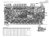
MAIN SECTION - • See page 8 for Circuit Boards Location. Location Ref. No. Location Ref. No. 3-7. No. Location Ref. PRINTED WIRING BOARD - STR-DE475 There are a few cases that the part printed on this diagram isn't mounted in this model. Location D505 F-4 D506 F-4 D508 F-3 D510 D-10 D560 C-8 D605 F-7 D606 F-8 D607 F-7 D610 C-9 D617 F-8 D627 F-11 D706...
MAIN SECTION - • See page 8 for Circuit Boards Location. Location Ref. No. Location Ref. No. 3-7. No. Location Ref. PRINTED WIRING BOARD - STR-DE475 There are a few cases that the part printed on this diagram isn't mounted in this model. Location D505 F-4 D506 F-4 D508 F-3 D510 D-10 D560 C-8 D605 F-7 D606 F-8 D607 F-7 D610 C-9 D617 F-8 D627 F-11 D706...
Service Manual
Page 16
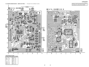
... 1251 IC 1201 IC 1007 16 16 DIGITAL (Page 18) IC 1002 IC 1010 IC 1009 IC 1013 (Page 14) IC 1003 STR-DE475 There are a few cases that the part printed on this diagram isn't mounted in this model. 3-9. No. No. IC 1004 IC 1005 IC 1006 IC 1011 • Semiconductor Location...
... 1251 IC 1201 IC 1007 16 16 DIGITAL (Page 18) IC 1002 IC 1010 IC 1009 IC 1013 (Page 14) IC 1003 STR-DE475 There are a few cases that the part printed on this diagram isn't mounted in this model. 3-9. No. No. IC 1004 IC 1005 IC 1006 IC 1011 • Semiconductor Location...
Service Manual
Page 18
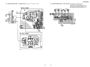
... C-12 D101 A-6 D102 A-8 D103 C-6 D109 B-12 D110 B-12 IC101 B-13 IC102 B-7 IC103 B-10 Q008 D-12 Q009 C-5 Q100 A-8 Q101 A-7 Q103 D-3 Q104 D-3 18 18 STR-DE475 There are a few cases that the part printed on this diagram isn't mounted in this model. (Page 20) (Page 14) IC 101 (Page 14) PRINTED WIRING BOARD - DISPLAY SECTION...
... C-12 D101 A-6 D102 A-8 D103 C-6 D109 B-12 D110 B-12 IC101 B-13 IC102 B-7 IC103 B-10 Q008 D-12 Q009 C-5 Q100 A-8 Q101 A-7 Q103 D-3 Q104 D-3 18 18 STR-DE475 There are a few cases that the part printed on this diagram isn't mounted in this model. (Page 20) (Page 14) IC 101 (Page 14) PRINTED WIRING BOARD - DISPLAY SECTION...
Service Manual
Page 20
PRINTED WIRING BOARD - 3-13. POWER SECTION -• See page 8 for Schematic Diagram. IC 1015 IC 1014 (Page 18) (Page 14) E model only 1-680-431- 20 20 VIDEO SECTION -• See page 8 for Circuit Boards Location. • See page 20 for Circuit Boards Location. (Page 14) (Page 14) IC 950 (Page 18) STR-DE475 3-14. There are a few cases that the part printed on this diagram isn't mounted in this model. PRINTED WIRING BOARD -
PRINTED WIRING BOARD - 3-13. POWER SECTION -• See page 8 for Schematic Diagram. IC 1015 IC 1014 (Page 18) (Page 14) E model only 1-680-431- 20 20 VIDEO SECTION -• See page 8 for Circuit Boards Location. • See page 20 for Circuit Boards Location. (Page 14) (Page 14) IC 950 (Page 18) STR-DE475 3-14. There are a few cases that the part printed on this diagram isn't mounted in this model. PRINTED WIRING BOARD -
Service Manual
Page 25
...• Items marked "*" are not stocked since they are critical for routine service. No. 1 1 1 2 2 2 2 2 2 2 2 3 4 5 Part No. Description Remarks 4-232-118-21 CASE (SILVER) 4-232-118-41 CASE(GOLD) 4-210-291-01 SCREW (CASE 3 TP2)(FOR BLACK) 4-210-291-21 SCREW...; Color Indication of Appearance Parts Example: KNOB, BALANCE (WHITE) . . . (RED) ↑ ↑ Parts of this parts list. • Abbreviation CND: Canadian model. Les composants identifiés par une marque 0 sont critiques pour la sécurité. MX : Mexican model. 6 STR-DE475 The components identified by mark...
...• Items marked "*" are not stocked since they are critical for routine service. No. 1 1 1 2 2 2 2 2 2 2 2 3 4 5 Part No. Description Remarks 4-232-118-21 CASE (SILVER) 4-232-118-41 CASE(GOLD) 4-210-291-01 SCREW (CASE 3 TP2)(FOR BLACK) 4-210-291-21 SCREW...; Color Indication of Appearance Parts Example: KNOB, BALANCE (WHITE) . . . (RED) ↑ ↑ Parts of this parts list. • Abbreviation CND: Canadian model. Les composants identifiés par une marque 0 sont critiques pour la sécurité. MX : Mexican model. 6 STR-DE475 The components identified by mark...
Service Manual
Page 26
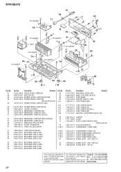
sont critiques pour la sécurité. STR-DE475 #2 not supplied 67 66 71 #1 63 #1 55 #3 #3 not supplied T901 not supplied 70 69 not supplied #2 #1 52 72 64 #2 #1 not supplied 51 #2 #1 61 not supplied #2...TUNER (AEP,UK,AUS,CH) BACK PANEL (DE475) (US) BACK PANEL (DE475) (CND) BACK PANEL (DE475) (AUS) BACK PANEL (DE475) (CH) 0 T901 0 T901 0 T901 0 T901 #1 4-233-753-51 BACK PANEL (DE475) (E) #2 4-233-753-61 BACK PANEL (DE475) (AEP) #3 4-233-753-71 BACK PANEL (DE475) (UK) 4-233-753-81 BACK PANEL (DE475) (MX) Part No. Replace only with mark ! No...
sont critiques pour la sécurité. STR-DE475 #2 not supplied 67 66 71 #1 63 #1 55 #3 #3 not supplied T901 not supplied 70 69 not supplied #2 #1 52 72 64 #2 #1 not supplied 51 #2 #1 61 not supplied #2...TUNER (AEP,UK,AUS,CH) BACK PANEL (DE475) (US) BACK PANEL (DE475) (CND) BACK PANEL (DE475) (AUS) BACK PANEL (DE475) (CH) 0 T901 0 T901 0 T901 0 T901 #1 4-233-753-51 BACK PANEL (DE475) (E) #2 4-233-753-61 BACK PANEL (DE475) (AEP) #3 4-233-753-71 BACK PANEL (DE475) (UK) 4-233-753-81 BACK PANEL (DE475) (MX) Part No. Replace only with mark ! No...
Service Manual
Page 27
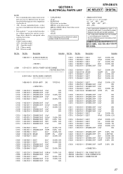
... , uPA... , µPA... , uPB... , µPB... , uPC... , µPC... , uPD..., µPD... SECTION 5 ELECTRICAL PARTS LIST STR-DE475 AC SELECT DIGITAL NOTE: • Due to standardization, replacements in the parts list may have some difference from the original one. • Items marked "*" are not stocked since they are critical...50V CNP501 1-784-927-11 PIN, CONNECTOR 12P * CNP502 1-564-506-11 PLUG, CONNECTOR 3P CNS103 1-794-006-11 CONNECTOR 20P 27 Part No. AUS : Australian model. Description Remarks Ref. CH : Chinese model. Ne les remplacer que par une pièce portant le ...
... , uPA... , µPA... , uPB... , µPB... , uPC... , µPC... , uPD..., µPD... SECTION 5 ELECTRICAL PARTS LIST STR-DE475 AC SELECT DIGITAL NOTE: • Due to standardization, replacements in the parts list may have some difference from the original one. • Items marked "*" are not stocked since they are critical...50V CNP501 1-784-927-11 PIN, CONNECTOR 12P * CNP502 1-564-506-11 PLUG, CONNECTOR 3P CNS103 1-794-006-11 CONNECTOR 20P 27 Part No. AUS : Australian model. Description Remarks Ref. CH : Chinese model. Ne les remplacer que par une pièce portant le ...
Service Manual
Page 28
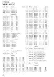
Part No. Description R1119 1-216-025-11 RES-CHIP 100 R1120 1-216-025-11 RES-CHIP 100 R1201 1-216-073-00 METAL CHIP 10K R1202 1-216-... 5.5V R1117 1-216-025-11 RES-CHIP 100 5% 1/10W C103 1-164-159-21 CERAMIC 0.1uF 50V R1118 1-216-025-11 RES-CHIP 100 5% 1/10W 28 STR-DE475 DIGITAL DISPLAY Ref. No. Description < DIODE > D1101 D1201 D1202 D1301 8-719-016-74 8-719-016-74 8-719-016-74 8-719-016-74 DIODE DIODE DIODE... IC uPC7805AHF IC1013 8-759-039-69 IC uPC7805AHF IC1201 8-759-099-06 IC M5218AFP-TE1 IC1251 8-759-099-06 IC M5218AFP-TE1 Remarks Ref. No. Part No.
Part No. Description R1119 1-216-025-11 RES-CHIP 100 R1120 1-216-025-11 RES-CHIP 100 R1201 1-216-073-00 METAL CHIP 10K R1202 1-216-... 5.5V R1117 1-216-025-11 RES-CHIP 100 5% 1/10W C103 1-164-159-21 CERAMIC 0.1uF 50V R1118 1-216-025-11 RES-CHIP 100 5% 1/10W 28 STR-DE475 DIGITAL DISPLAY Ref. No. Description < DIODE > D1101 D1201 D1202 D1301 8-719-016-74 8-719-016-74 8-719-016-74 8-719-016-74 DIODE DIODE DIODE... IC uPC7805AHF IC1013 8-759-039-69 IC uPC7805AHF IC1201 8-759-099-06 IC M5218AFP-TE1 IC1251 8-759-099-06 IC M5218AFP-TE1 Remarks Ref. No. Part No.
Service Manual
Page 29
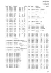
...-880-31 CERAMIC 0.022uF 10% 0.022uF 10% 0.022uF 10% 0.022uF 10% 0.022uF 10% Remarks 50V 50V 50V 50V 50V Ref. No. FB100 Part No. C104 C105 C106 C107 C108 Part No. Description < FERRITE BEAD > 1-412-473-41 INDUCTOR 0UH (US,CND) < FILTER > Remarks C109 C110 C111 C112 C113 1-164-159-11 CERAMIC... 4.7K 5% 1/4W F 10K 5% 1/4W 330 5% 1/4W 470 5% 1/4W F 680 5% 1/4W F 1K 5% 1/4W F 1.5K 5% 1/4W F 2.2K 5% 1/4W F 150 5% 1/4W F 100 5% 1/4W 100 5% 1/4W 100 5% 1/4W 29 STR-DE475 DISPLAY Ref.
...-880-31 CERAMIC 0.022uF 10% 0.022uF 10% 0.022uF 10% 0.022uF 10% 0.022uF 10% Remarks 50V 50V 50V 50V 50V Ref. No. FB100 Part No. C104 C105 C106 C107 C108 Part No. Description < FERRITE BEAD > 1-412-473-41 INDUCTOR 0UH (US,CND) < FILTER > Remarks C109 C110 C111 C112 C113 1-164-159-11 CERAMIC... 4.7K 5% 1/4W F 10K 5% 1/4W 330 5% 1/4W 470 5% 1/4W F 680 5% 1/4W F 1K 5% 1/4W F 1.5K 5% 1/4W F 2.2K 5% 1/4W F 150 5% 1/4W F 100 5% 1/4W 100 5% 1/4W 100 5% 1/4W 29 STR-DE475 DISPLAY Ref.
Service Manual
Page 30
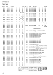
... S100 S101 S102 S103 S104 S105 S106 S107 S110 S111 S112 S113 S114 S115 S116 S117 S118 S120 S121 S122 S123 S124 S125 S126 S127 Part No. R058 R062 R064 R065 R098 Part No. STR-DE475 DISPLAY Ref.
... S100 S101 S102 S103 S104 S105 S106 S107 S110 S111 S112 S113 S114 S115 S116 S117 S118 S120 S121 S122 S123 S124 S125 S126 S127 Part No. R058 R062 R064 R065 R098 Part No. STR-DE475 DISPLAY Ref.


