Primary User Manual
Page 1
Refer to them whenever you call upon your Sony dealer regarding this product. Record the serial number in the space provided below. Serial No. STR-DE1075 © 2001 Sony Corporation 4-235-988-13(1) FM Stereo FM-AM Receiver Operating Instructions Owner's Record The model and serial numbers are located on the rear panel. Model No.
Refer to them whenever you call upon your Sony dealer regarding this product. Record the serial number in the space provided below. Serial No. STR-DE1075 © 2001 Sony Corporation 4-235-988-13(1) FM Stereo FM-AM Receiver Operating Instructions Owner's Record The model and serial numbers are located on the rear panel. Model No.
Primary User Manual
Page 2
...to operate this equipment does cause harmful interference to the presence of the NEC that this manual describe the controls on the receiver. This receiver incorporates Dolby* Digital and Pro Logic Surround and the DTS** Digital Surround System. * Manufactured under license from that may cause... on the remote is intended to alert the user to radio or television reception, which the receiver is a U.S. Note for energy efficiency. As an ENERGY STAR® partner, Sony Corporation has determined that provides guidelines for this model. Tip The instructions in accordance with the...
...to operate this equipment does cause harmful interference to the presence of the NEC that this manual describe the controls on the receiver. This receiver incorporates Dolby* Digital and Pro Logic Surround and the DTS** Digital Surround System. * Manufactured under license from that may cause... on the remote is intended to alert the user to radio or television reception, which the receiver is a U.S. Note for energy efficiency. As an ENERGY STAR® partner, Sony Corporation has determined that provides guidelines for this model. Tip The instructions in accordance with the...

Primary User Manual
Page 3
..."Now Demonstration Mode!! Note Running the demonstration will activate the first time you !" Thank you turn the receiver on, the demonstration will be cleared, see "Clearing the receiver's memory" on the power. To cancel the demonstration Press ?/1 to turn on page 16. 3 Table ... display 25 Enjoying Surround Sound Selecting a sound field 26 Understanding the multi channel surround displays 30 Customizing sound fields 31 Receiving Broadcasts Direct tuning 36 Automatic tuning 36 Preset tuning 37 Other Operations Naming preset stations and program sources 38 Recording 38...
..."Now Demonstration Mode!! Note Running the demonstration will activate the first time you !" Thank you turn the receiver on, the demonstration will be cleared, see "Clearing the receiver's memory" on the power. To cancel the demonstration Press ?/1 to turn on page 16. 3 Table ... display 25 Enjoying Surround Sound Selecting a sound field 26 Understanding the multi channel surround displays 30 Customizing sound fields 31 Receiving Broadcasts Direct tuning 36 Automatic tuning 36 Preset tuning 37 Other Operations Naming preset stations and program sources 38 Recording 38...
Primary User Manual
Page 6
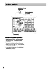
Antenna hookups AM loop antenna (supplied) FM wire antenna (supplied) DIGITAL ANTENNA CTRL S IN CTRL S STATUS IN CTRL S OUT CTRL...IN VIDEO OUT VIDEO IN VIDEO S-VIDEO S-VIDEO OUT IN VIDEO VIDEO MD/DAT OPTICAL IN MD/DAT OPTICAL OUT U FM CONTROL 75Ω A1 MONITOR COAXIAL AUDIO IN L AUDIO IN AUDIO OUT AUDIO IN AUDIO OUT AUDIO IN L DVD...To prevent noise pickup, keep the AM loop antenna away from the receiver and other components. • Be sure to fully extend the FM wire antenna. • After connecting the FM wire antenna, keep it as horizontal as possible. • Do not...
Antenna hookups AM loop antenna (supplied) FM wire antenna (supplied) DIGITAL ANTENNA CTRL S IN CTRL S STATUS IN CTRL S OUT CTRL...IN VIDEO OUT VIDEO IN VIDEO S-VIDEO S-VIDEO OUT IN VIDEO VIDEO MD/DAT OPTICAL IN MD/DAT OPTICAL OUT U FM CONTROL 75Ω A1 MONITOR COAXIAL AUDIO IN L AUDIO IN AUDIO OUT AUDIO IN AUDIO OUT AUDIO IN L DVD...To prevent noise pickup, keep the AM loop antenna away from the receiver and other components. • Be sure to fully extend the FM wire antenna. • After connecting the FM wire antenna, keep it as horizontal as possible. • Do not...
Primary User Manual
Page 8
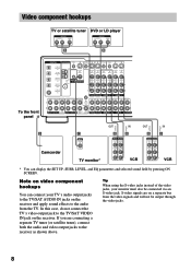
...by pressing ON SCREEN. In this case, do not connect the TV's video output jack to the receiver as shown above. S-video signals are connecting a separate TV tuner (or satellite tuner), connect both...to the TV/SAT VIDEO IN jack on a separate bus from the TV. If you are on the receiver. Video component hookups TV or satellite tuner DVD or LD player OUTPUT AUDIO OUT R L VIDEO OUT ... IN VIDEO S-VIDEO S-VIDEO OUT IN VIDEO VIDEO MD/DAT OPTICAL IN MD/DAT OPTICAL OUT U FM CONTROL 75Ω A1 MONITOR COAXIAL AUDIO IN L AUDIO IN AUDIO OUT AUDIO IN AUDIO OUT AUDIO...
...by pressing ON SCREEN. In this case, do not connect the TV's video output jack to the receiver as shown above. S-video signals are connecting a separate TV tuner (or satellite tuner), connect both...to the TV/SAT VIDEO IN jack on a separate bus from the TV. If you are on the receiver. Video component hookups TV or satellite tuner DVD or LD player OUTPUT AUDIO OUT R L VIDEO OUT ... IN VIDEO S-VIDEO S-VIDEO OUT IN VIDEO VIDEO MD/DAT OPTICAL IN MD/DAT OPTICAL OUT U FM CONTROL 75Ω A1 MONITOR COAXIAL AUDIO IN L AUDIO IN AUDIO OUT AUDIO IN AUDIO OUT AUDIO...
Primary User Manual
Page 9
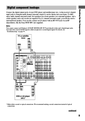
... an RF OUT jack via an RF demodulator, like the Sony MOD-RF1 (not supplied). You must first convert the RF signal to bring the multi channel surround sound of a movie theater into your DVD player and satellite tuner (etc.) to the receiver's digital input jacks to either coaxial or optical connections... S-VIDEO IN VIDEO OUT VIDEO IN VIDEO S-VIDEO S-VIDEO OUT IN VIDEO VIDEO MD/DAT OPTICAL IN MD/DAT OPTICAL OUT DVD/LD COAXIAL IN U FM CONTROL 75Ω A1 MONITOR COAXIAL AUDIO IN L AUDIO IN AUDIO OUT AUDIO IN AUDIO OUT AUDIO IN L R TV/SAT DVD/LD VIDEO 2 R VIDEO 1 ...
... an RF OUT jack via an RF demodulator, like the Sony MOD-RF1 (not supplied). You must first convert the RF signal to bring the multi channel surround sound of a movie theater into your DVD player and satellite tuner (etc.) to the receiver's digital input jacks to either coaxial or optical connections... S-VIDEO IN VIDEO OUT VIDEO IN VIDEO S-VIDEO S-VIDEO OUT IN VIDEO VIDEO MD/DAT OPTICAL IN MD/DAT OPTICAL OUT DVD/LD COAXIAL IN U FM CONTROL 75Ω A1 MONITOR COAXIAL AUDIO IN L AUDIO IN AUDIO OUT AUDIO IN AUDIO OUT AUDIO IN L R TV/SAT DVD/LD VIDEO 2 R VIDEO 1 ...
Primary User Manual
Page 10
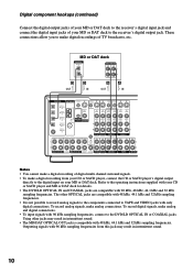
...S-VIDEO S-VIDEO IN IN VIDEO VIDEO OUT VIDEO IN VIDEO S-VIDEO S-VIDEO OUT IN VIDEO VIDEO MD/DAT OPTICAL IN MD/DAT OPTICAL OUT U FM CONTROL 75Ω A1 MONITOR COAXIAL AUDIO IN L AUDIO IN AUDIO OUT AUDIO IN AUDIO OUT AUDIO IN L DVD/LD COAXIAL IN R TV/.... Outputting signals with 96 kHz sampling frequencies from your CD or SACD player, connect the CD or SACD player's digital output directly to the receiver's digital output jack. To record analog signals, make a digital recording from this jack may result in intermittent sound. 10 These connections allow you...
...S-VIDEO S-VIDEO IN IN VIDEO VIDEO OUT VIDEO IN VIDEO S-VIDEO S-VIDEO OUT IN VIDEO VIDEO MD/DAT OPTICAL IN MD/DAT OPTICAL OUT U FM CONTROL 75Ω A1 MONITOR COAXIAL AUDIO IN L AUDIO IN AUDIO OUT AUDIO IN AUDIO OUT AUDIO IN L DVD/LD COAXIAL IN R TV/.... Outputting signals with 96 kHz sampling frequencies from your CD or SACD player, connect the CD or SACD player's digital output directly to the receiver's digital output jack. To record analog signals, make a digital recording from this jack may result in intermittent sound. 10 These connections allow you...
Primary User Manual
Page 11
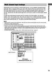
...S-VIDEO IN VIDEO S-VIDEO IN VIDEO OUT VIDEO IN VIDEO S-VIDEO S-VIDEO OUT IN VIDEO VIDEO MD/DAT OPTICAL IN MD/DAT OPTICAL OUT U FM CONTROL 75Ω A1 MONITOR COAXIAL AUDIO IN L AUDIO IN AUDIO OUT AUDIO IN AUDIO OUT AUDIO IN L DVD/LD COAXIAL IN R TV/... the connections described below, adjust the level of the DVD player's multi channel decoder. Hooking Up the Components Multi channel input hookups Although this receiver incorporates a multi channel decoder, it is also equipped with your DVD player is directly output from the DVD player or multi channel decoder. &#...
...S-VIDEO IN VIDEO S-VIDEO IN VIDEO OUT VIDEO IN VIDEO S-VIDEO S-VIDEO OUT IN VIDEO VIDEO MD/DAT OPTICAL IN MD/DAT OPTICAL OUT U FM CONTROL 75Ω A1 MONITOR COAXIAL AUDIO IN L AUDIO IN AUDIO OUT AUDIO IN AUDIO OUT AUDIO IN L DVD/LD COAXIAL IN R TV/... the connections described below, adjust the level of the DVD player's multi channel decoder. Hooking Up the Components Multi channel input hookups Although this receiver incorporates a multi channel decoder, it is also equipped with your DVD player is directly output from the DVD player or multi channel decoder. &#...
Primary User Manual
Page 12
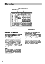
... 1, CD 2, or CD 3, be sure to set the command mode to "CD 2" and connect the changer to the VIDEO 2 jacks on the receiver. 12 Note If you have a Sony CD changer with a COMMAND MODE selector If your CD player, SACD player, tape deck, or MD deck for details. Other hookups CTRL S (STATUS... VIDEO S-VIDEO S-VIDEO IN IN VIDEO VIDEO OUT VIDEO IN VIDEO S-VIDEO S-VIDEO OUT IN VIDEO VIDEO MD/DAT OPTICAL IN MD/DAT OPTICAL OUT U FM CONTROL 75Ω A1 MONITOR COAXIAL AUDIO IN L AUDIO IN AUDIO OUT AUDIO IN AUDIO OUT AUDIO IN L DVD/LD COAXIAL IN R TV/SAT DVD...
... 1, CD 2, or CD 3, be sure to set the command mode to "CD 2" and connect the changer to the VIDEO 2 jacks on the receiver. 12 Note If you have a Sony CD changer with a COMMAND MODE selector If your CD player, SACD player, tape deck, or MD deck for details. Other hookups CTRL S (STATUS... VIDEO S-VIDEO S-VIDEO IN IN VIDEO VIDEO OUT VIDEO IN VIDEO S-VIDEO S-VIDEO OUT IN VIDEO VIDEO MD/DAT OPTICAL IN MD/DAT OPTICAL OUT U FM CONTROL 75Ω A1 MONITOR COAXIAL AUDIO IN L AUDIO IN AUDIO OUT AUDIO IN AUDIO OUT AUDIO IN L DVD/LD COAXIAL IN R TV/SAT DVD...
Primary User Manual
Page 13
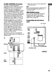
...from the supplied audio/ video/control S cable. When your TV, satellite tuner, monitor, VCR, etc., for VCR, etc.) jack on the receiver to a stereo amplifier located in another room (see page 25). The following illustration is connected to VIDEO 1 or DVD/LD whenever you play your VCR or ... shown below , input mode of S-LINK CONTROL S hookups between the receiver, a TV, a VCR, and a DVD player. The following connections also change to video input whenever you have a S-LINK CONTROL Scompatible Sony TV, satellite tuner, monitor, DVD player or VCR, use the 2ND ROOM OUT jacks to output ...
...from the supplied audio/ video/control S cable. When your TV, satellite tuner, monitor, VCR, etc., for VCR, etc.) jack on the receiver to a stereo amplifier located in another room (see page 25). The following illustration is connected to VIDEO 1 or DVD/LD whenever you play your VCR or ... shown below , input mode of S-LINK CONTROL S hookups between the receiver, a TV, a VCR, and a DVD player. The following connections also change to video input whenever you have a S-LINK CONTROL Scompatible Sony TV, satellite tuner, monitor, DVD player or VCR, use the 2ND ROOM OUT jacks to output ...
Primary User Manual
Page 14
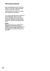
... turn the whole system on or off . Do not connect high-wattage electrical home appliances such as electric irons, fans, or TVs to the receiver (see page 17). Other hookups (continued) Before connecting the AC power cord of your audio/ video components to a wall outlet. If you ...connect other audio/video components to the AC OUTLET(s) on the receiver, the receiver will supply power to the connected component(s), allowing you turn the receiver on the rear panel. Connect the AC power cord(s) of this receiver to a wall outlet, connect the speaker system to this outlet. 14
... turn the whole system on or off . Do not connect high-wattage electrical home appliances such as electric irons, fans, or TVs to the receiver (see page 17). Other hookups (continued) Before connecting the AC power cord of your audio/ video components to a wall outlet. If you ...connect other audio/video components to the AC OUTLET(s) on the receiver, the receiver will supply power to the connected component(s), allowing you turn the receiver on the rear panel. Connect the AC power cord(s) of this receiver to a wall outlet, connect the speaker system to this outlet. 14
Primary User Manual
Page 16
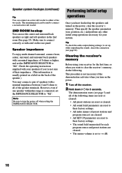
... each program source and preset stations are cleared. • The master volume is usually printed on a label on the power, clear the receiver's memory. The demonstration starts (see page 22). The remaining jack can be used to "8Ω". This procedure is connected, set up the... surround back speakers with your system. Check the operating instructions supplied with a nominal impedance of 8 ohms or higher, and set to clear the receiver's memory, do the following items are reset or cleared: • All preset stations are reset or cleared. • All sound field parameters...
... each program source and preset stations are cleared. • The master volume is usually printed on a label on the power, clear the receiver's memory. The demonstration starts (see page 22). The remaining jack can be used to "8Ω". This procedure is connected, set up the... surround back speakers with your system. Check the operating instructions supplied with a nominal impedance of 8 ohms or higher, and set to clear the receiver's memory, do the following items are reset or cleared: • All preset stations are reset or cleared. • All sound field parameters...

Primary User Manual
Page 17
... it from the surround left and right speakers. Multi channel surround setup For the best possible surround sound, all of your room (etc.). However, the receiver lets you B A A 45° C C 90° D 20° Note Do not place the center speaker farther away from the listening ... up to 40 feet from the listening position (A). Hooking Up and Setting Up the Speaker System Performing initial setup operations Before using your receiver for other settings. continued 17 For the adjustable parameters, see the table on a stand or hanging it is no space behind you...
... it from the surround left and right speakers. Multi channel surround setup For the best possible surround sound, all of your room (etc.). However, the receiver lets you B A A 45° C C 90° D 20° Note Do not place the center speaker farther away from the listening ... up to 40 feet from the listening position (A). Hooking Up and Setting Up the Speaker System Performing initial setup operations Before using your receiver for other settings. continued 17 For the adjustable parameters, see the table on a stand or hanging it is no space behind you...
Primary User Manual
Page 20
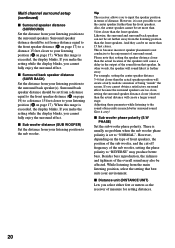
... speaker distance 3~6 feet closer than the front speakers. While listening from the main listening position, select the setting that speaker. Tip The receiver allows you cannot obtain a satisfactory surround effect because the surround speakers are too close, setting the surround speaker distance closer (shorter) than ...feet closer than 15 feet closer. If you make the setting while the display blinks, you select either feet or meters as the receiver of the sub woofer, setting the phase polarity to the sound often results in terms of surround sound. However, depending on the ...
... speaker distance 3~6 feet closer than the front speakers. While listening from the main listening position, select the setting that speaker. Tip The receiver allows you cannot obtain a satisfactory surround effect because the surround speakers are too close, setting the surround speaker distance closer (shorter) than ...feet closer than 15 feet closer. If you make the setting while the display blinks, you select either feet or meters as the receiver of the sub woofer, setting the phase polarity to the sound often results in terms of surround sound. However, depending on the ...
Primary User Manual
Page 22
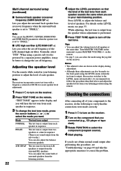
...Checking the connections After connecting all speakers at a time in sequence. When using the LEVEL menu (when the test tone is output, the receiver switches to the LEVEL menu automatically), we recommend you follow the procedure described above and adjust the speaker levels from the sub woofer.) You... frequency (SURR BACK SP >) Lets you adjust the surround back speaker bass crossover frequency when the surround back speaker is set to the receiver, do not obtain normal sound output after performing this procedure, see page 33. The test tone is output from each speaker in sequence....
...Checking the connections After connecting all speakers at a time in sequence. When using the LEVEL menu (when the test tone is output, the receiver switches to the LEVEL menu automatically), we recommend you follow the procedure described above and adjust the speaker levels from the sub woofer.) You... frequency (SURR BACK SP >) Lets you adjust the surround back speaker bass crossover frequency when the surround back speaker is set to the receiver, do not obtain normal sound output after performing this procedure, see page 33. The test tone is output from each speaker in sequence....
Primary User Manual
Page 25
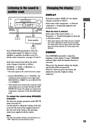
...the function. DIRECT is selected Index name of the supplied remote to the dimmest setting, the display and the blue LED are turned off the receiver. 25 Each time you have been entered, or it is automatically set to MULTI CH 1 or 2 DIRECT. • Only signals from components connected...the remote. Refer to adjust the volume in another room Changing the display DISPLAY Basic Operations •• SPEAKERS 2ND ROOM OUT AUDIO IN Stereo amplifier SPEAKERS Press 2ND ROOM repeatedly to select the analog audio signals for output to only the digital input jacks. Index name does not ...
...the function. DIRECT is selected Index name of the supplied remote to the dimmest setting, the display and the blue LED are turned off the receiver. 25 Each time you have been entered, or it is automatically set to MULTI CH 1 or 2 DIRECT. • Only signals from components connected...the remote. Refer to adjust the volume in another room Changing the display DISPLAY Basic Operations •• SPEAKERS 2ND ROOM OUT AUDIO IN Stereo amplifier SPEAKERS Press 2ND ROOM repeatedly to select the analog audio signals for output to only the digital input jacks. Index name does not ...
Primary User Manual
Page 26
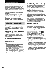
...sound field You can enjoy surround sound simply by selecting one of the receiver's preprogrammed sound fields. As the Director's "visual and audio united" effect can be ...to set the speaker parameters before enjoying surround sound. When these sound fields are output in stereo automatically, and the sound field is indicated in the display. They bring the exciting and ... the display lights up -todate facilities in Hollywood. You can identify the encoding format of Sony Pictures Entertainment's BGM recording studio. 26 Press SOUND FIELD MODE repeatedly to reproduce the sound...
...sound field You can enjoy surround sound simply by selecting one of the receiver's preprogrammed sound fields. As the Director's "visual and audio united" effect can be ...to set the speaker parameters before enjoying surround sound. When these sound fields are output in stereo automatically, and the sound field is indicated in the display. They bring the exciting and ... the display lights up -todate facilities in Hollywood. You can identify the encoding format of Sony Pictures Entertainment's BGM recording studio. 26 Press SOUND FIELD MODE repeatedly to reproduce the sound...
Primary User Manual
Page 30
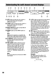
... are compatible with MPEG format. Since the LFE signal is output from the front 2 channels. 5 ; or "NORMAL SURROUND" is selected. 4 MPEG: Lights up when the receiver applies Pro Logic processing to indicate the level. L (Front Left), R (Front Right), C (Center (monaural)), SL (Surround Left), SR (Surround Right), S (Surround (monaural .... Understanding the multi channel surround displays 12 3 4 5 67 8 9 0 OPTCOAXMULTI CH IN 1 2 a DIGITAL ; The boxes around the letters vary to "NO", and "A.F.D." SW L CR STEREO MONO MEMORY SL SR RDS SSB 2ND ROOM SP.
... are compatible with MPEG format. Since the LFE signal is output from the front 2 channels. 5 ; or "NORMAL SURROUND" is selected. 4 MPEG: Lights up when the receiver applies Pro Logic processing to indicate the level. L (Front Left), R (Front Right), C (Center (monaural)), SL (Surround Left), SR (Surround Right), S (Surround (monaural .... Understanding the multi channel surround displays 12 3 4 5 67 8 9 0 OPTCOAXMULTI CH IN 1 2 a DIGITAL ; The boxes around the letters vary to "NO", and "A.F.D." SW L CR STEREO MONO MEMORY SL SR RDS SSB 2ND ROOM SP.
Primary User Manual
Page 31
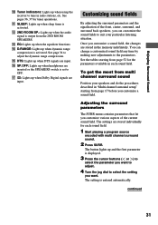
.... 2 Press SURR. The setting is activated. To get the most from the 2ND ROOM SPEAKERS. Enjoying Surround Sound 0 Tuner indicators: Lights up when using the receiver to select the parameter you want . Customizing sound fields By adjusting the surround parameters and the equalization of the current sound field. qf D.RANGE: Lights...
.... 2 Press SURR. The setting is activated. To get the most from the 2ND ROOM SPEAKERS. Enjoying Surround Sound 0 Tuner indicators: Lights up when using the receiver to select the parameter you want . Customizing sound fields By adjusting the surround parameters and the equalization of the current sound field. qf D.RANGE: Lights...
Primary User Manual
Page 32
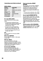
... WALL S__I__H REVERB S__I__L FRONT REVERB SCREEN DEPTH VIR. Reverberation (REVERB) Lets you specify the Pro Logic decoding setting. • To set the receiver to the original reverberations in your listening environment by "CINEMA STUDIO EX A, B, C" and "SEMI CINEMA STUDIO EX A, B, C" off or on...MID ON Pro Logic (PRO LOGIC) Lets you control the spacing of the Dolby surround encoded flag, select "ON". • To set the receiver not to simulate a sonically longer (L) or shorter (S) room. The midpoint designates a standard room with no adjustment. Front reverberation (FRONT REVERB) ...
... WALL S__I__H REVERB S__I__L FRONT REVERB SCREEN DEPTH VIR. Reverberation (REVERB) Lets you specify the Pro Logic decoding setting. • To set the receiver to the original reverberations in your listening environment by "CINEMA STUDIO EX A, B, C" and "SEMI CINEMA STUDIO EX A, B, C" off or on...MID ON Pro Logic (PRO LOGIC) Lets you control the spacing of the Dolby surround encoded flag, select "ON". • To set the receiver not to simulate a sonically longer (L) or shorter (S) room. The midpoint designates a standard room with no adjustment. Front reverberation (FRONT REVERB) ...


