
Operating Instructions (primary manual)
Page 6
... cable. 11 Headphones jack (page 10) This jack outputs audio signals to boost the bass sound from the speaker. 10 SYSTEM CONNECTOR (page 8) This connector inputs signals from the media engine when the display and the media engine are connected with papers, etc. Identifying parts and controls ... low power consumption mode, and lights up in green when the monitor is in orange when the monitor is turned on the screen. LCD display SONY Front 1 2 3 4 5 6 7 Rear E (volume) +1- El Ducts These are used to the headphones. 8 9 1 11 9 (!) (Power) switch and indicator (pages 9, 17, 22) ...
... cable. 11 Headphones jack (page 10) This jack outputs audio signals to boost the bass sound from the speaker. 10 SYSTEM CONNECTOR (page 8) This connector inputs signals from the media engine when the display and the media engine are connected with papers, etc. Identifying parts and controls ... low power consumption mode, and lights up in green when the monitor is in orange when the monitor is turned on the screen. LCD display SONY Front 1 2 3 4 5 6 7 Rear E (volume) +1- El Ducts These are used to the headphones. 8 9 1 11 9 (!) (Power) switch and indicator (pages 9, 17, 22) ...

Operating Instructions (primary manual)
Page 7
...* DDC (Display Data Channel) is the same as left. The pin assignment is a standard of the computer or other audio equipment. HD15 (RGB) input 1 connector (INPUT1) (page 8) This connector inputs RGB video signals (0.700 Vp-p, positive) and SYNC signals. VCXXXD OCXXXD) S gOO® Pin No. 1 2 3 4 5 6 7 8 9 10... lights up in red when the display is turned off . Caution Be sure to install the media engine vertically shown as H. 16 AC IN connector (page 9) This connector provides AC power to the monitor. Media engine BON 13 18 0 141 .1!.% 0 12 0 151 0 16 C• I 17 .N\ 19...
...* DDC (Display Data Channel) is the same as left. The pin assignment is a standard of the computer or other audio equipment. HD15 (RGB) input 1 connector (INPUT1) (page 8) This connector inputs RGB video signals (0.700 Vp-p, positive) and SYNC signals. VCXXXD OCXXXD) S gOO® Pin No. 1 2 3 4 5 6 7 8 9 10... lights up in red when the display is turned off . Caution Be sure to install the media engine vertically shown as H. 16 AC IN connector (page 9) This connector provides AC power to the monitor. Media engine BON 13 18 0 141 .1!.% 0 12 0 151 0 16 C• I 17 .N\ 19...
Operating Instructions (primary manual)
Page 8
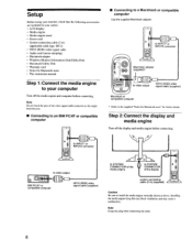
... PC/AT or compatible computer i==D HD15 (RGB) video signal cable (supplied) to SYSTEM CONNECTOR of the media engine ISMEM 0 to SYSTEM CONNECTOR of the video signal cable connector as above. Step 2:Connect the display and media engine Turn off the media engine and ...8226; Windows Monitor Information Disk/Utility Disk • Macintosh Utility Disk • Warranty card • Notes for further details. to INPUT1 or INPUT2 connector Macintosh adapter (supplied)* • • 0 to video output HD15 (RGB) video signal cable (supplied) Macintosh or compatible computer * Refer ...
... PC/AT or compatible computer i==D HD15 (RGB) video signal cable (supplied) to SYSTEM CONNECTOR of the media engine ISMEM 0 to SYSTEM CONNECTOR of the video signal cable connector as above. Step 2:Connect the display and media engine Turn off the media engine and ...8226; Windows Monitor Information Disk/Utility Disk • Macintosh Utility Disk • Warranty card • Notes for further details. to INPUT1 or INPUT2 connector Macintosh adapter (supplied)* • • 0 to video output HD15 (RGB) video signal cable (supplied) Macintosh or compatible computer * Refer ...

Operating Instructions (primary manual)
Page 10
... input signal and corresponding input indicator, "I" (INPUT 1) or "2" (INPUT 2) change each time you press this monitor using the INPUT I and INPUT 2 connectors. buttons. Connect your monitor. After a few seconds, the monitor enters the power saving mode.If this happens, select the other audio equipment using the supplied... the stereo speaker of your monitor is in low power consumption mode or power saving mode, no signal is input to the selected connector, NO INPUT SIGNAL appears on the screen. button to adjust the volume. Using the headphones jack You can listen to the audio ...
... input signal and corresponding input indicator, "I" (INPUT 1) or "2" (INPUT 2) change each time you press this monitor using the INPUT I and INPUT 2 connectors. buttons. Connect your monitor. After a few seconds, the monitor enters the power saving mode.If this happens, select the other audio equipment using the supplied... the stereo speaker of your monitor is in low power consumption mode or power saving mode, no signal is input to the selected connector, NO INPUT SIGNAL appears on the screen. button to adjust the volume. Using the headphones jack You can listen to the audio ...

Operating Instructions (primary manual)
Page 12
...select the menu item. INPUT 2 3 Adjust the menu. This setting is stored in memory for the signal from the currently selected input connector. 1 Press the (brightness) button. Adjusting the black level of an image (BRIGHTNESS) Brightness adjustment is made using the RESET menu. For...buttons to adjust the brightness. Press the OK button to display the desired menu. See page 15 for the signal from the currently selected input connector. 1 Press the O (contrast) button. Press the t(+)/4(-) buttons to adjust. If no buttons are displayed in memory for more information about ...
...select the menu item. INPUT 2 3 Adjust the menu. This setting is stored in memory for the signal from the currently selected input connector. 1 Press the (brightness) button. Adjusting the black level of an image (BRIGHTNESS) Brightness adjustment is made using the RESET menu. For...buttons to adjust the brightness. Press the OK button to display the desired menu. See page 15 for the signal from the currently selected input connector. 1 Press the O (contrast) button. Press the t(+)/4(-) buttons to adjust. If no buttons are displayed in memory for more information about ...

Operating Instructions (primary manual)
Page 19
..., see "Trouble symptoms and remedies" on the screen This indicates that the video signal cable has been disconnected from the currently selected connector. Check the following messages appears on the screen This indicates that no signal is not supported by 99.9 kHz and 99 Hz, ...xkHz/ xxHz If CABLE DISCONNECTED appears on page 20. OINFORMATION NO INPUT SIGNAL INPUT: 1 GO TO POWER SAVE INPUT: This indicates the currently selected connector (INPUT: 1 or INPUT: 2). GO TO POWER SAVE The monitor will enter the power saving mode after about 4 seconds from the message is...
..., see "Trouble symptoms and remedies" on the screen This indicates that the video signal cable has been disconnected from the currently selected connector. Check the following messages appears on the screen This indicates that no signal is not supported by 99.9 kHz and 99 Hz, ...xkHz/ xxHz If CABLE DISCONNECTED appears on page 20. OINFORMATION NO INPUT SIGNAL INPUT: 1 GO TO POWER SAVE INPUT: This indicates the currently selected connector (INPUT: 1 or INPUT: 2). GO TO POWER SAVE The monitor will enter the power saving mode after about 4 seconds from the message is...
Operating Instructions (primary manual)
Page 20
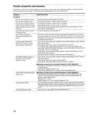
... (only XGA mode at 75 Hz) • If you replaced an old monitor with this monitor ("SDM-N50") from low power consumption mode because the user sensor fails to the connected equipment's instruction manual. This... Use the self-diagnostics function (page 22). • The monitor cannot return from among the Sony monitors in the proper bus slot. Press the 0 (power) switch twice to OFF, the ...Check that the input select setting is correct (page 10). • Check that the video input connector's pins are firmly seated in their sockets (page 8). • Press the AC power switch twice...
... (only XGA mode at 75 Hz) • If you replaced an old monitor with this monitor ("SDM-N50") from low power consumption mode because the user sensor fails to the connected equipment's instruction manual. This... Use the self-diagnostics function (page 22). • The monitor cannot return from among the Sony monitors in the proper bus slot. Press the 0 (power) switch twice to OFF, the ...Check that the input select setting is correct (page 10). • Check that the video input connector's pins are firmly seated in their sockets (page 8). • Press the AC power switch twice...

Operating Instructions (primary manual)
Page 22
... green, blue), the monitor is working properly. Count the number of seconds between orange flashes of the () (power) indicator and inform your authorized Sony dealer of your monitor. Design and specifications are subject to turn the monitor off and then on green) Audio output 2W x 2 Headphones jack Stereo... indicator is still flashing, there is green 1 Turn off the AC power switch and disconnect the video signal cables from the INPUT1 and INPUT2 connectors of the media engine. 2 Press the AC power switch twice to note the model name and serial number of 16 1(12 Accepts level 0.5 ...
... green, blue), the monitor is working properly. Count the number of seconds between orange flashes of the () (power) indicator and inform your authorized Sony dealer of your monitor. Design and specifications are subject to turn the monitor off and then on green) Audio output 2W x 2 Headphones jack Stereo... indicator is still flashing, there is green 1 Turn off the AC power switch and disconnect the video signal cables from the INPUT1 and INPUT2 connectors of the media engine. 2 Press the AC power switch twice to note the model name and serial number of 16 1(12 Accepts level 0.5 ...
Marketing Specifications
Page 4
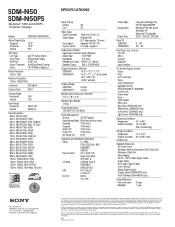
... Inputs/Outputs Signal Input Connector Stereo Minijack Audio Input 0.5V RMS Impedance 47k ohms Headphone Output 15mW x 2, 16ohms Speaker Output 2W x 2 (SDM-N50) Display Dimensions (WxHxD) SDM-N50 14.0" x 13.7" x 7.3" SDM-N50PS 14.0" x 11" x 1" (w/o stand) 14.0" x 8.9" x 8" (tilt 90˚, w/stand) Display Weight SMD-N50 SMD-N50PS 5.9 lbs. 3.3 lbs. As an International Energy Star Partner, Sony Corporation has determined...
... Inputs/Outputs Signal Input Connector Stereo Minijack Audio Input 0.5V RMS Impedance 47k ohms Headphone Output 15mW x 2, 16ohms Speaker Output 2W x 2 (SDM-N50) Display Dimensions (WxHxD) SDM-N50 14.0" x 13.7" x 7.3" SDM-N50PS 14.0" x 11" x 1" (w/o stand) 14.0" x 8.9" x 8" (tilt 90˚, w/stand) Display Weight SMD-N50 SMD-N50PS 5.9 lbs. 3.3 lbs. As an International Energy Star Partner, Sony Corporation has determined...