Operating Instructions
Page 1
... expense. For the customers in the separate service or guarantee documents. For the customers in accordance with the instruction manual, may cause undesired operation. 4-541-888-02(1) ࣭ྔ 1.8 kg mmʣ 2- 5 102 85 67 Remote Control Panel Operation Guide 310 332.2 355 ͢ɻ RCP-1500 RCP-1501 RCP-1530 102 67 85 © 2014 Sony Corporation Printed in a commercial environment. R O M 仕...
... expense. For the customers in the separate service or guarantee documents. For the customers in accordance with the instruction manual, may cause undesired operation. 4-541-888-02(1) ࣭ྔ 1.8 kg mmʣ 2- 5 102 85 67 Remote Control Panel Operation Guide 310 332.2 355 ͢ɻ RCP-1500 RCP-1501 RCP-1530 102 67 85 © 2014 Sony Corporation Printed in a commercial environment. R O M 仕...
Operating Instructions
Page 2
... (RCP-1500/1501 only) EXT I/O 8-pin RJ-45 (1) 8-pin multi-connector, female (1) 8-pin multi-connector, female (1) 9-pin, female (1) Supplied accessories Operation guide (1) Operation manual (CD-ROM) (1) Optional accessories External I/O connector JAE DE-9PF-N 1-568-182-11 CCA-5-3 remote cable (3 m) CCA-5-10 remote cable (10 m) CCA-5-30 remote cable (30 m) Design and specifications are subject to this product. For the customers in the U.S.A. Please visit http://www.pro.sony.eu/warranty for configuring and controlling Sony's studio and broadcast cameras. SONY...
... (RCP-1500/1501 only) EXT I/O 8-pin RJ-45 (1) 8-pin multi-connector, female (1) 8-pin multi-connector, female (1) 9-pin, female (1) Supplied accessories Operation guide (1) Operation manual (CD-ROM) (1) Optional accessories External I/O connector JAE DE-9PF-N 1-568-182-11 CCA-5-3 remote cable (3 m) CCA-5-10 remote cable (10 m) CCA-5-30 remote cable (30 m) Design and specifications are subject to this product. For the customers in the U.S.A. Please visit http://www.pro.sony.eu/warranty for configuring and controlling Sony's studio and broadcast cameras. SONY...
Operation Guide
Page 2
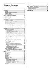
... 4 Examples of System Configurations 5 Supported devices 7 Operating Cameras 7 Names and Functions of Parts 8 Operation Panel 8 Connector Panel 26 Installation 27 Connection Precautions 27 Setting the Status Screen Display 27 Setting the Clock 29 Setting the LAN Connection 30 Setting LEGACY Mode 30 Setting BRIDGE Mode 31 Setting Multi-Camera System (MCS) Mode 32 Changing the Output Destination for Previews 33 Settings 34 Setting the User Interface 34 To set the sounds 34 To set the brightness of the LEDs...
... 4 Examples of System Configurations 5 Supported devices 7 Operating Cameras 7 Names and Functions of Parts 8 Operation Panel 8 Connector Panel 26 Installation 27 Connection Precautions 27 Setting the Status Screen Display 27 Setting the Clock 29 Setting the LAN Connection 30 Setting LEGACY Mode 30 Setting BRIDGE Mode 31 Setting Multi-Camera System (MCS) Mode 32 Changing the Output Destination for Previews 33 Settings 34 Setting the User Interface 34 To set the sounds 34 To set the brightness of the LEDs...
Operation Guide
Page 4
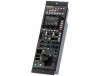
... and master black adjustment block employs joystick type control. • The RCP-1500 incorporates an LCD display with direct operation switches and a touch panel, which allows you to mount up a multi-camera control system, not only can a system be built using a LAN. In a system that compares favorably with the MSU. It is possible to connect by using multiple camera systems that can configure settings. • Switches You can...
... and master black adjustment block employs joystick type control. • The RCP-1500 incorporates an LCD display with direct operation switches and a touch panel, which allows you to mount up a multi-camera control system, not only can a system be built using a LAN. In a system that compares favorably with the MSU. It is possible to connect by using multiple camera systems that can configure settings. • Switches You can...

Operation Guide
Page 17
... the setting value do not match. c BLACK/FLARE (manual black balance/flare balance) knobs These knobs adjust the black balance when the FLARE button is not lit, and the flare balance when the FLARE button is not lit. d FLARE (flare balance mode) button This button changes the adjustment mode of the assignable adjustment knob, see page 44. 2 Iris/master control black adjustment block a Camera number/tally display window This window displays an amber number for manual adjustment using...
... the setting value do not match. c BLACK/FLARE (manual black balance/flare balance) knobs These knobs adjust the black balance when the FLARE button is not lit, and the flare balance when the FLARE button is not lit. d FLARE (flare balance mode) button This button changes the adjustment mode of the assignable adjustment knob, see page 44. 2 Iris/master control black adjustment block a Camera number/tally display window This window displays an amber number for manual adjustment using...

Operation Guide
Page 18
... display window This window displays the iris setting as an F number. h MASTER BLACK RELATIVE button This button changes the manual adjustment mode of manual adjustment. i Iris indicators The corresponding LED lights according to the CLOSE value set by the COARSE knob. 18 D EXT: Lights when the digital extender function is used. Does not function. Pressing the PANEL ACTIVE button also causes this button is for adjusting the iris automatically. It does not work in...
... display window This window displays the iris setting as an F number. h MASTER BLACK RELATIVE button This button changes the manual adjustment mode of manual adjustment. i Iris indicators The corresponding LED lights according to the CLOSE value set by the COARSE knob. 18 D EXT: Lights when the digital extender function is used. Does not function. Pressing the PANEL ACTIVE button also causes this button is for adjusting the iris automatically. It does not work in...

Operation Guide
Page 21
... you to adjust the R, G, and B signals in order from left half of the BLACK/ FLARE knobs. a Camera number/tally display window This window displays an amber number for manual adjustment using the WHITE, BLACK, FLARE, DETAIL, and assignable knobs between flare balance and black balance by the control panel. In absolute value mode, a knob indication value becomes that setting value. D EXT: Lights when the digital extender function is turned ON. 21...
... you to adjust the R, G, and B signals in order from left half of the BLACK/ FLARE knobs. a Camera number/tally display window This window displays an amber number for manual adjustment using the WHITE, BLACK, FLARE, DETAIL, and assignable knobs between flare balance and black balance by the control panel. In absolute value mode, a knob indication value becomes that setting value. D EXT: Lights when the digital extender function is turned ON. 21...

Operation Guide
Page 22
... full range from the EXT I/O connector. Pressing the PANEL ACTIVE button also causes this button to use a "Memory Stick Duo." j MASTER BLACK RELATIVE button This button changes the manual adjustment mode of the IRIS control lever. Indication Off Lit in green Lit in this button is for OPEN, referenced to the iris setting. It does not work in relative values. Press the switch axially to output preview key signals from...
... full range from the EXT I/O connector. Pressing the PANEL ACTIVE button also causes this button to use a "Memory Stick Duo." j MASTER BLACK RELATIVE button This button changes the manual adjustment mode of the IRIS control lever. Indication Off Lit in green Lit in this button is for OPEN, referenced to the iris setting. It does not work in relative values. Press the switch axially to output preview key signals from...

Operation Guide
Page 26
... remote) connector (8-pin multi-connector, female) (RCP-1500/1501 only) This is a spare connector. d EXT I/O connector (D-sub 9-pin, female) This is used for connecting to the RCP/CNU connector of the CCU or the RCP connector of the CNU. b CCU/CNU REMOTE (CCU/CNU remote) connector (8-pin multi-connector, female) This is for external interface connections. 26 Connector Panel RCP-1500/1501 RCP-1530 a (network) connector (8-pin RJ-45) This is for connecting to a 10BASET/100BASE-TX hub. This connector can receive power supplied...
... remote) connector (8-pin multi-connector, female) (RCP-1500/1501 only) This is a spare connector. d EXT I/O connector (D-sub 9-pin, female) This is used for connecting to the RCP/CNU connector of the CCU or the RCP connector of the CNU. b CCU/CNU REMOTE (CCU/CNU remote) connector (8-pin multi-connector, female) This is for external interface connections. 26 Connector Panel RCP-1500/1501 RCP-1530 a (network) connector (8-pin RJ-45) This is for connecting to a 10BASET/100BASE-TX hub. This connector can receive power supplied...

Operation Guide
Page 27
... mode. 3 Display the RCP Config screen. (page 50) RCP Config Engineer Mode Exit Customize Date /Time Display /Sound Network Mode Information VR Setting Security 2 Use the removed screw to the adjustment knobs of the control panel. The adjustment functions can select from several types of contents displayed on menu operations, see page 50. Installation For details on the status screen. Setting the Status Screen Display You can set the type of status screen that appears when no MENU buttons...
... mode. 3 Display the RCP Config screen. (page 50) RCP Config Engineer Mode Exit Customize Date /Time Display /Sound Network Mode Information VR Setting Security 2 Use the removed screw to the adjustment knobs of the control panel. The adjustment functions can select from several types of contents displayed on menu operations, see page 50. Installation For details on the status screen. Setting the Status Screen Display You can set the type of status screen that appears when no MENU buttons...

Operation Guide
Page 28
... Customize screen for setting the assigned adjustment knob appears. Function assignments of assignable functions is saved to the selected status screen type. The Status Customize screen appears. A list of the adjustment knobs are reset to display type). (The [Knob Customize] button may not appear, depending on the operation panel are displayed. [Select Knob $Knob 1 - Status Customize Engineer Mode Exit Status Display OFF Menu Type Control Value...
... Customize screen for setting the assigned adjustment knob appears. Function assignments of assignable functions is saved to the selected status screen type. The Status Customize screen appears. A list of the adjustment knobs are reset to display type). (The [Knob Customize] button may not appear, depending on the operation panel are displayed. [Select Knob $Knob 1 - Status Customize Engineer Mode Exit Status Display OFF Menu Type Control Value...

Operation Guide
Page 32
.... 1 Enter engineer mode. (page 51) 2 Press the MENU button. Press the IP address input field, and then use when connecting a LAN cable to the control panel and using it to a CCU via a CCA cable and connecting a LAN cable to be the master in engineer mode. 3 Display the RCP Config screen. (page 50) RCP Config Engineer Mode Exit Customize Date /Time Display /Sound Network Mode Information VR Setting Security Option Key Backup 4 Press [Network]. Network Engineer Mode Exit Network Info CNS...
.... 1 Enter engineer mode. (page 51) 2 Press the MENU button. Press the IP address input field, and then use when connecting a LAN cable to the control panel and using it to a CCU via a CCA cable and connecting a LAN cable to be the master in engineer mode. 3 Display the RCP Config screen. (page 50) RCP Config Engineer Mode Exit Customize Date /Time Display /Sound Network Mode Information VR Setting Security Option Key Backup 4 Press [Network]. Network Engineer Mode Exit Network Info CNS...

Operation Guide
Page 34
... [Display/Sound]. RE: Sets the sound played when the adjustment knobs are received, and when the panel is displayed in each type One of sound. Settings RCP-1530 For details on menu operations, see page 50. Press the tab to set each of the sound setting screens to play the sound. To confirm a sound, press [Sound Test] to turn ON/OFF the sound. To turn ON/OFF the sound for each of the sound settings. RCP-1500...
... [Display/Sound]. RE: Sets the sound played when the adjustment knobs are received, and when the panel is displayed in each type One of sound. Settings RCP-1530 For details on menu operations, see page 50. Press the tab to set each of the sound setting screens to play the sound. To confirm a sound, press [Sound Test] to turn ON/OFF the sound. To turn ON/OFF the sound for each of the sound settings. RCP-1500...

Operation Guide
Page 35
... the camera number/tally display window. Tally: Sets the brightness of the menu operation block. 1 Display the RCP Config screen. (page 50) RCP Config Exit Display /Sound Information Security 2 Press [Display/Sound]. The LED screen appears. The Display/Sound screen appears. 3 Turn the SELECT knob to select "LCD." The following settings can also be configured. RCP-1500/1501 Display/Sound Clear LED 2/5 Exit Switch Tally Other Master 50 50 50 50 4 Turn the adjustment knobs to light the button. [RE Click] : Turns...
... the camera number/tally display window. Tally: Sets the brightness of the menu operation block. 1 Display the RCP Config screen. (page 50) RCP Config Exit Display /Sound Information Security 2 Press [Display/Sound]. The LED screen appears. The Display/Sound screen appears. 3 Turn the SELECT knob to select "LCD." The following settings can also be configured. RCP-1500/1501 Display/Sound Clear LED 2/5 Exit Switch Tally Other Master 50 50 50 50 4 Turn the adjustment knobs to light the button. [RE Click] : Turns...

Operation Guide
Page 40
..., turn on the control panel while holding down Auto Setup Enable The following settings can protect operation of the control panel with a security code To prevent unwanted operations, you can be configured. [Full Lock] : Press this to light the button and prohibit all operations of the control panel. [View Mode] : Press this to light the button and prohibit all operations of the control panel except for viewing data. [Full Paint] : Under the default settings...
..., turn on the control panel while holding down Auto Setup Enable The following settings can protect operation of the control panel with a security code To prevent unwanted operations, you can be configured. [Full Lock] : Press this to light the button and prohibit all operations of the control panel. [View Mode] : Press this to light the button and prohibit all operations of the control panel except for viewing data. [Full Paint] : Under the default settings...
Operation Guide
Page 50
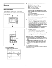
... procedure to display the RCP screen. 50 To display the RCP screen When setting the control panel, use various operation menus to adjust system devices and perform other operations with the message, and then press [OK]. Menus Menu Operations You can use the following menu items are displayed in the setting and adjustment screen, press a tab to switch to the setting item. 4 Set or adjust the item. • Turn the adjustment knob (or press the button) in...
... procedure to display the RCP screen. 50 To display the RCP screen When setting the control panel, use various operation menus to adjust system devices and perform other operations with the message, and then press [OK]. Menus Menu Operations You can use the following menu items are displayed in the setting and adjustment screen, press a tab to switch to the setting item. 4 Set or adjust the item. • Turn the adjustment knob (or press the button) in...

Operation Guide
Page 74
... a signal combining R and G. Sets the band for V Detail. Function Sets the camera. Sets the operation mode of the auto setup. Sets the number of revolutions of revolutions are independent when this is connected. However, if the internal temperature exceeds a specified value, the number of the camera fan to the G channel. Generates V Detail from the G channel. Selects a step test waveform. Selects the 720P generation mode. This is ON. Menu items...
... a signal combining R and G. Sets the band for V Detail. Function Sets the camera. Sets the operation mode of the auto setup. Sets the number of revolutions of revolutions are independent when this is connected. However, if the internal temperature exceeds a specified value, the number of the camera fan to the G channel. Generates V Detail from the G channel. Selects a step test waveform. Selects the 720P generation mode. This is ON. Menu items...

Operation Guide
Page 77
... received. Sets the switch brightness. Sets other LED settings. Adjusts the brightness of the operation sound. Item Screen Saver PIX/WF Matrix Gate Extend Call Option ON Preview Wait Time Type PIX/WF Syncro PIX/WF Control Mode Gate Interlock ON Time Mode Function Sets the screen saver to flash for a while when a call is the volume of the backlight. Sets the operation for all sounds emitted from the speakers. Confirms the set...
... received. Sets the switch brightness. Sets other LED settings. Adjusts the brightness of the operation sound. Item Screen Saver PIX/WF Matrix Gate Extend Call Option ON Preview Wait Time Type PIX/WF Syncro PIX/WF Control Mode Gate Interlock ON Time Mode Function Sets the screen saver to flash for a while when a call is the volume of the backlight. Sets the operation for all sounds emitted from the speakers. Confirms the set...

Operation Guide
Page 80
... not used, this button is pressed even when CHARACTER display is disabled. • Use [Display] to display or hide the camera/BPU operation state. • Use [Menu] to select a setting value. 3 Press [Enter]. To operate while displaying the camera/BPU menu • Press [Enter] to switch to the setting mode and confirm changing of the setting value. • Press [Cancel] to end the setting mode and cancel changing of the setting value. • Turn the adjustment...
... not used, this button is pressed even when CHARACTER display is disabled. • Use [Display] to display or hide the camera/BPU operation state. • Use [Menu] to select a setting value. 3 Press [Enter]. To operate while displaying the camera/BPU menu • Press [Enter] to switch to the setting mode and confirm changing of the setting value. • Press [Cancel] to end the setting mode and cancel changing of the setting value. • Turn the adjustment...

Operation Guide
Page 81
... menu allows you want to their standard state, press [Reset]. 3 Press [Set]. The setting changes are displayed.) 2 To return all RCP assignments to control. In addition, the function is not available when an MSU-900/950 is not selected, only devices with established connections to change RCP assignments Selecting [RCP Assignment] in MCS mode. To change RCP assignments. RCP Assignment Exit Panel-01 Camera-01 Set Cancel All Camera Reset 1 Use...
... menu allows you want to their standard state, press [Reset]. 3 Press [Set]. The setting changes are displayed.) 2 To return all RCP assignments to control. In addition, the function is not available when an MSU-900/950 is not selected, only devices with established connections to change RCP assignments Selecting [RCP Assignment] in MCS mode. To change RCP assignments. RCP Assignment Exit Panel-01 Camera-01 Set Cancel All Camera Reset 1 Use...


