Service Manual
Page 8
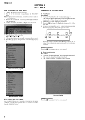
...is changed into the drawing check. 2. Press the [] keys, change the test mode menu page 1/page 2. > > > > WHITE LIGHT GRAY DARK GRAY BLACK < < < < When the setting of "17. Press the [] keys, change the image files. 3. Note: Confirm the method of ... test mode menu 1. 8 Releasing method: Press the [ ] key, return to turn the power off. Touch the "Drawing with point Procedure: 1. The scanned coordinate is copied under the "READER" drive. Press the key as "/Sony Reader/software/images") 2. PRS-650 SECTION 3 TEST MODE HOW TO ENTER THE TEST MODE 1.
...is changed into the drawing check. 2. Press the [] keys, change the test mode menu page 1/page 2. > > > > WHITE LIGHT GRAY DARK GRAY BLACK < < < < When the setting of "17. Press the [] keys, change the image files. 3. Note: Confirm the method of ... test mode menu 1. 8 Releasing method: Press the [ ] key, return to turn the power off. Touch the "Drawing with point Procedure: 1. The scanned coordinate is copied under the "READER" drive. Press the key as "/Sony Reader/software/images") 2. PRS-650 SECTION 3 TEST MODE HOW TO ENTER THE TEST MODE 1.
Service Manual
Page 9
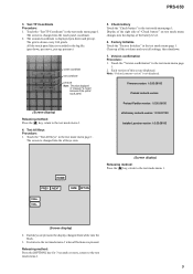
..." is drawn every 100 pixels. The screen is recorded in the test mode menu page 1. Factory Initialize Touch the "Factory Initialize" in the test mode menu page 1. Each keys are pressed. PRS-650 3. Test TP Coordinate Procedure: 1. Touch the "Test TP Coordinate" in the test mode menu page 1. The grid is not displayed. All... VOL+ VOL- (Screen display) Releasing method: Press the [ ] key, return to the test mode menu 1 when all buttons are pressed, the display changed into the black. 3. It returns to the test mode menu 1. (Screen display) 2.
..." is drawn every 100 pixels. The screen is recorded in the test mode menu page 1. Factory Initialize Touch the "Factory Initialize" in the test mode menu page 1. Each keys are pressed. PRS-650 3. Test TP Coordinate Procedure: 1. Touch the "Test TP Coordinate" in the test mode menu page 1. The grid is not displayed. All... VOL+ VOL- (Screen display) Releasing method: Press the [ ] key, return to the test mode menu 1 when all buttons are pressed, the display changed into the black. 3. It returns to the test mode menu 1. (Screen display) 2.

Service Manual
Page 12
...ample: KNOB, BALANCE (WHITE) . . . (RED) ↑ ↑ Parts Color Cabinet's Color • Abbreviation CND : Canadian model 4-1. PRS-650 SECTION 4 EXPLODED VIEWS Note: • -XX and -X mean standardized parts, so they may have some difference from the original one. • Items... (for SILVER/RED) SCREW (M1.4) (EG), PRECISION PAN (for SILVER/RED) SCREW (M1.4) (EG), PRECISION PAN (for BLACK) SHEET (ORNAMENT), ADHESIVE 4 4-193-524-01 SCREW, SHAFT (for BLACK) 4 4-193-524-11 SCREW, SHAFT (for SILVER/RED) Remark 12 CASE (REAR) SECTION not supplied 8 case and frame ...
...ample: KNOB, BALANCE (WHITE) . . . (RED) ↑ ↑ Parts Color Cabinet's Color • Abbreviation CND : Canadian model 4-1. PRS-650 SECTION 4 EXPLODED VIEWS Note: • -XX and -X mean standardized parts, so they may have some difference from the original one. • Items... (for SILVER/RED) SCREW (M1.4) (EG), PRECISION PAN (for SILVER/RED) SCREW (M1.4) (EG), PRECISION PAN (for BLACK) SHEET (ORNAMENT), ADHESIVE 4 4-193-524-01 SCREW, SHAFT (for BLACK) 4 4-193-524-11 SCREW, SHAFT (for SILVER/RED) Remark 12 CASE (REAR) SECTION not supplied 8 case and frame ...

Service Manual
Page 13
...), LIGHT 56 3-225-996-07 SCREW (M1.4) (EG), PRECISION PAN 57 A-1786-096-A ORNAMENT (T) ASSY (for BLACK) 57 A-1786-271-A ORNAMENT (T) ASSY (for BLACK) 59 4-193-524-01 SCREW, SHAFT 60 A-1786-095-A CASE ASSY (BLACK) 60 A-1786-272-A CASE ASSY (SILVER) 60 A-1786-275-A CASE ASSY (RED) 13 No. 58 58 Part... No. CASE AND FRAME (REAR) SECTION Note: This illustration is view from the MAIN board. 51 52 57 56 53 55 52 54 53 52 PRS-650 59 60 59 58 59 main section Ref. 4-2.
...), LIGHT 56 3-225-996-07 SCREW (M1.4) (EG), PRECISION PAN 57 A-1786-096-A ORNAMENT (T) ASSY (for BLACK) 57 A-1786-271-A ORNAMENT (T) ASSY (for BLACK) 59 4-193-524-01 SCREW, SHAFT 60 A-1786-095-A CASE ASSY (BLACK) 60 A-1786-272-A CASE ASSY (SILVER) 60 A-1786-275-A CASE ASSY (RED) 13 No. 58 58 Part... No. CASE AND FRAME (REAR) SECTION Note: This illustration is view from the MAIN board. 51 52 57 56 53 55 52 54 53 52 PRS-650 59 60 59 58 59 main section Ref. 4-2.

Service Manual
Page 14
... X-2560-525-1 LED BOARD, COMPLETE SCREW (M1.4) (EG), PRECISION PAN CABLE, FLEXIBLE FLAT (10PIN) SCREW (M1.4X2), TOOTHED LOCK MAIN BOARD, COMPLETE (for SERVICE) (for BLACK) (US, CND) 105 X-2560-526-1 MAIN BOARD, COMPLETE (for SERVICE) (for SILVER) (US, CND) 105 X-2560-527-1 MAIN BOARD, COMPLETE (for SERVICE) (for... ADHESIVE 111 111 112 113 BAT1 4-191-771-01 4-191-771-11 A-1798-663-A 4-265-515-01 A-1786-696-A KNOB (VOL) (for BLACK) KNOB (VOL) (for an absolutely new part when you remove the BATTERY ASSY (BAT1) built into this set. PRS-650 4-3. No. 101 102 103 104 105 Part No.
... X-2560-525-1 LED BOARD, COMPLETE SCREW (M1.4) (EG), PRECISION PAN CABLE, FLEXIBLE FLAT (10PIN) SCREW (M1.4X2), TOOTHED LOCK MAIN BOARD, COMPLETE (for SERVICE) (for BLACK) (US, CND) 105 X-2560-526-1 MAIN BOARD, COMPLETE (for SERVICE) (for SILVER) (US, CND) 105 X-2560-527-1 MAIN BOARD, COMPLETE (for SERVICE) (for... ADHESIVE 111 111 112 113 BAT1 4-191-771-01 4-191-771-11 A-1798-663-A 4-265-515-01 A-1786-696-A KNOB (VOL) (for BLACK) KNOB (VOL) (for an absolutely new part when you remove the BATTERY ASSY (BAT1) built into this set. PRS-650 4-3. No. 101 102 103 104 105 Part No.
