
Operating Instructions
Page 3
...not cause harmful interference, and (2) this equipment does cause harmful interference to operate this manual. 3-GB If this device must accept any changes or modifications not expressly approved in this manual could void your authority to radio or television reception, which the receiver is valid only...radio/TV technician for products marketed in the European GB Union. • OpenMG and its logo are trademarks of the FCC Rules. SONY MZ-N505 Tested To Comply With FCC Standards FOR HOME OR OFFICE USE The CE mark on a circuit different from Dolby Laboratories. • ...
...not cause harmful interference, and (2) this equipment does cause harmful interference to operate this manual. 3-GB If this device must accept any changes or modifications not expressly approved in this manual could void your authority to radio or television reception, which the receiver is valid only...radio/TV technician for products marketed in the European GB Union. • OpenMG and its logo are trademarks of the FCC Rules. SONY MZ-N505 Tested To Comply With FCC Standards FOR HOME OR OFFICE USE The CE mark on a circuit different from Dolby Laboratories. • ...

Service Manual
Page 1
...-459-01 2002A0500-1 C 2002.1 Sony Corporation Personal Audio Company Published by Sony Engineering Corporation in monaural Maximum 320 min. Model Name Using Similar Mechanism Mechanism Type Optical Pick-up block with 7 mm aperture.) Recording and playback time When using MDW-80 Maximum 160 min. SERVICE MANUAL Ver 1.0 2002. 01 MZ-N505 US Model Canadian Model...
...-459-01 2002A0500-1 C 2002.1 Sony Corporation Personal Audio Company Published by Sony Engineering Corporation in monaural Maximum 320 min. Model Name Using Similar Mechanism Mechanism Type Optical Pick-up block with 7 mm aperture.) Recording and playback time When using MDW-80 Maximum 160 min. SERVICE MANUAL Ver 1.0 2002. 01 MZ-N505 US Model Canadian Model...

Service Manual
Page 2
...with the JEITA (Japan Electronics and Information Technology Industries Association) standard. 4) When using a 100% fully charged rechargeable battery. 5) When using a Sony LR6 (SG) "STAMINA " alkaline dry battery (produced in .) without notice. SAFETY-RELATED COMPONENT WARNING!! Mass Approx. 104 g (3.7 oz) ... THIS MANUAL OR IN SUPPLEMENTS PUBLISHED BY SONY. 2 ATTENTION AU COMPOSANT AYANT RAPPORT À LA SÉCURITÉ! LP2/LP4 Modulation system EFM (Eight to Fourteen Modulation) Number of batteries. 2) When you record, use a fully charged rechargeable battery. MZ-N505 Coding ...
...with the JEITA (Japan Electronics and Information Technology Industries Association) standard. 4) When using a 100% fully charged rechargeable battery. 5) When using a Sony LR6 (SG) "STAMINA " alkaline dry battery (produced in .) without notice. SAFETY-RELATED COMPONENT WARNING!! Mass Approx. 104 g (3.7 oz) ... THIS MANUAL OR IN SUPPLEMENTS PUBLISHED BY SONY. 2 ATTENTION AU COMPOSANT AYANT RAPPORT À LA SÉCURITÉ! LP2/LP4 Modulation system EFM (Eight to Fourteen Modulation) Number of batteries. 2) When you record, use a fully charged rechargeable battery. MZ-N505 Coding ...

Service Manual
Page 5
... I DELETE button 12 5 F REC REMAIN/REMAIN (remaining time/tracks) indication Lights up when group mode is extracted from instruction manual. When flashing, the recorder is rotating for recording, playing or editing an MD. Lookingat the controls The recorder 6 The display...tactile dot. ./> (search/AMS) button x (stop ) • ENTER button C X (pause) • CAPS button D EDIT button E VOL +/- SECTION 2 GENERAL MZ-N505 This section is on. H T MARK button I J K LM N A MONO (monaural) indication B LP mode indication C Mega bass indication D Disc indication Shows that the...
... I DELETE button 12 5 F REC REMAIN/REMAIN (remaining time/tracks) indication Lights up when group mode is extracted from instruction manual. When flashing, the recorder is rotating for recording, playing or editing an MD. Lookingat the controls The recorder 6 The display...tactile dot. ./> (search/AMS) button x (stop ) • ENTER button C X (pause) • CAPS button D EDIT button E VOL +/- SECTION 2 GENERAL MZ-N505 This section is on. H T MARK button I J K LM N A MONO (monaural) indication B LP mode indication C Mega bass indication D Disc indication Shows that the...

Service Manual
Page 13
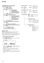
Also, the manual mode allows each adjustment is automatically executed in the text, indicates a set key. Set LCD display SETTING METHOD OF TEST MODE There are three different ... the set and the remote commander. 13 While pressing the x key, press the keys on the remote commander with the following dis- SECTION 4 TEST MODE MZ-N505 OUTLINE • This set provides the Overall adjustment mode that allows CD and MO discs to set the test mode: All lit 1 Short SL801 (TEST...
Also, the manual mode allows each adjustment is automatically executed in the text, indicates a set key. Set LCD display SETTING METHOD OF TEST MODE There are three different ... the set and the remote commander. 13 While pressing the x key, press the keys on the remote commander with the following dis- SECTION 4 TEST MODE MZ-N505 OUTLINE • This set provides the Overall adjustment mode that allows CD and MO discs to set the test mode: All lit 1 Short SL801 (TEST...
Service Manual
Page 14
... this mode is written. key is used to adjust or check the operation of the set by function. MZ-N505 CONFIGURATION OF TEST MODE [Test Mode $Display Check Mode%] Press the > or [VOL +] key [Manual Mode] Press the x key [Servo Adjustment] [Audio Adjustment] [Power Supply Adjustment] [OP Alignment Adjustment] Press the . Set the...
... this mode is written. key is used to adjust or check the operation of the set by function. MZ-N505 CONFIGURATION OF TEST MODE [Test Mode $Display Check Mode%] Press the > or [VOL +] key [Manual Mode] Press the x key [Servo Adjustment] [Audio Adjustment] [Power Supply Adjustment] [OP Alignment Adjustment] Press the . Set the...

Service Manual
Page 15
... by one when the . Quit the self-diagnosis result display mode, and press the x key to return to "SECTION 5 ELECTRICAL ADJUSTMENTS" (see page 13). 2. MZ-N505 5. SELF-DIAGNOSIS RESULT DISPLAY MODE This set uses the self-diagnostic function system in which if an error occurred during the recording or playing, the...time the > key is recorded as a guideline of how long the optical pickup has been used, and by one as shown below . Quit the manual mode, and press the x key to return to the simple display mode. 4. By checking this mode at the time when an error occurred in the...
... by one when the . Quit the self-diagnosis result display mode, and press the x key to return to "SECTION 5 ELECTRICAL ADJUSTMENTS" (see page 13). 2. MZ-N505 5. SELF-DIAGNOSIS RESULT DISPLAY MODE This set uses the self-diagnostic function system in which if an error occurred during the recording or playing, the...time the > key is recorded as a guideline of how long the optical pickup has been used, and by one as shown below . Quit the manual mode, and press the x key to return to the simple display mode. 4. By checking this mode at the time when an error occurred in the...

Service Manual
Page 19
SECTION 5 ELECTRICAL ADJUSTMENTS MZ-N505 OUTLINE • In this set, automatic adjustment of ...adjusted values following tools and measuring instruments. • Test CD disc TDYS-1 (Part No. : 4-963-646-01) • SONY MO disc available on the market • Digital voltmeter • Laser power meter LPM-8001 (Part No. : J-2501-046-A) ...; Caution: This adjustment must be performed continuously in reverse order with no particular description in the manual mode. • A key having no disc loaded. r Overall Mode 6. Use ...
SECTION 5 ELECTRICAL ADJUSTMENTS MZ-N505 OUTLINE • In this set, automatic adjustment of ...adjusted values following tools and measuring instruments. • Test CD disc TDYS-1 (Part No. : 4-963-646-01) • SONY MO disc available on the market • Digital voltmeter • Laser power meter LPM-8001 (Part No. : J-2501-046-A) ...; Caution: This adjustment must be performed continuously in reverse order with no particular description in the manual mode. • A key having no disc loaded. r Overall Mode 6. Use ...

Service Manual
Page 20
..., 866) - Change x2/x1 switching temperature threshold value (+10°C t +5°C) (item numbers 873, 874) 2. NV adjusted values modifying procedure 1) Select manual mode of the test mode, and set item number 775 (see page 14). Change BatFlg value (item number 741) - Set LCD display 771 AD ** **: ...+3dB compared to 775) - Set LCD display 776 **: Adjusted value AD ** 20 Item numbers in the manual mode at the shipment, but these will be changed before the overall adjustment. - MZ-N505 • Change of the test mode, and set item number 771 (see page 14). In this set,...
..., 866) - Change x2/x1 switching temperature threshold value (+10°C t +5°C) (item numbers 873, 874) 2. NV adjusted values modifying procedure 1) Select manual mode of the test mode, and set item number 775 (see page 14). Change BatFlg value (item number 741) - Set LCD display 771 AD ** **: ...+3dB compared to 775) - Set LCD display 776 **: Adjusted value AD ** 20 Item numbers in the manual mode at the shipment, but these will be changed before the overall adjustment. - MZ-N505 • Change of the test mode, and set item number 771 (see page 14). In this set,...

Service Manual
Page 21
... that the adjusted value becomes 81. 36) Press the X key to write the adjusted value. 37) Select manual mode of the test mode, and set item number 865 (see page 14). Set LCD display 867 ###: Address...) Press the X key to write the adjusted value. 25) Select manual mode of the test mode, and set item number 777 (see page 14). MZ-N505 23) Adjust with the [VOL +] key (adjusted value up) or... [VOL --] key (adjusted value down ) so that the adjusted value becomes B9. 42) Press the X key to write the adjusted value. 43) Select manual...
... that the adjusted value becomes 81. 36) Press the X key to write the adjusted value. 37) Select manual mode of the test mode, and set item number 865 (see page 14). Set LCD display 867 ###: Address...) Press the X key to write the adjusted value. 25) Select manual mode of the test mode, and set item number 777 (see page 14). MZ-N505 23) Adjust with the [VOL +] key (adjusted value up) or... [VOL --] key (adjusted value down ) so that the adjusted value becomes B9. 42) Press the X key to write the adjusted value. 43) Select manual...

Service Manual
Page 22
... 874 ###: Address **: Adjusted value ###S** 59) Adjust with the following steps. 1. Vc PWM Duty (L) adjustment (item number: 762) r 2. Select the manual mode of Power Supply Manual Adjustment 1. Press the X key to the AP912 (VCO) on the MAIN board, and adjust [VOL +] key (voltage up ) or [VOL --] key...(see page 14). Vrec PWM Duty (L) adjustment (item number: 766) r 6. Make sure that the voltage becomes 2.50 ± 0.05 V. MZ-N505 49) Select manual mode of the test mode, and set item number 872 (see page 14). digital voltmeter MAIN board AP912 (VCO) AP602 (GND) 2. Connect a...
... 874 ###: Address **: Adjusted value ###S** 59) Adjust with the following steps. 1. Vc PWM Duty (L) adjustment (item number: 762) r 2. Select the manual mode of Power Supply Manual Adjustment 1. Press the X key to the AP912 (VCO) on the MAIN board, and adjust [VOL +] key (voltage up ) or [VOL --] key...(see page 14). Vrec PWM Duty (L) adjustment (item number: 766) r 6. Make sure that the voltage becomes 2.50 ± 0.05 V. MZ-N505 49) Select manual mode of the test mode, and set item number 872 (see page 14). digital voltmeter MAIN board AP912 (VCO) AP602 (GND) 2. Connect a...

Service Manual
Page 23
...Adjusted value AD ** 1. Measure the ambient temperature. 3. Connect a digital voltmeter to 1.75 V. digital voltmeter MAIN board TP (VREC) AP602 (GND) 2. MZ-N505 2. Adjustment and Connection Location: MAIN board (See page 25) • Adjustment Method of Vrec PWM Duty (L) (item number: 766) Set LCD display ...25) • Adjustment Method of Vl PWM Duty (H) (item number: 765) Set LCD display 765 AD ** **: Adjusted value 1. Select the manual mode of Vrec PWM Duty (H) (item number: 767) Set LCD display 767 **: Adjusted value AD ** 1. Connect a digital voltmeter to write the...
...Adjusted value AD ** 1. Measure the ambient temperature. 3. Connect a digital voltmeter to 1.75 V. digital voltmeter MAIN board TP (VREC) AP602 (GND) 2. MZ-N505 2. Adjustment and Connection Location: MAIN board (See page 25) • Adjustment Method of Vrec PWM Duty (L) (item number: 766) Set LCD display ...25) • Adjustment Method of Vl PWM Duty (H) (item number: 765) Set LCD display 765 AD ** **: Adjusted value 1. Select the manual mode of Vrec PWM Duty (H) (item number: 767) Set LCD display 767 **: Adjusted value AD ** 1. Connect a digital voltmeter to write the...

Service Manual
Page 24
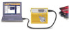
MZ-N505 LASER POWER CHECK • Connection laser power meter Optical pick-up moves to quit the manual mode, and activate the test mode (display check mode). tor R521 at this time is below 44 mV. 7. Press the x key to the most inward ... (see page 14), and set the laser power adjusting mode (item number 010). tor R521 at this time is below 80 mV. 13. Select the manual mode of resis- Set LCD display 010 Laser 2. Check that the laser power meter reading is 0.81 ± 0.08 mW. 6. Check that the laser power...
MZ-N505 LASER POWER CHECK • Connection laser power meter Optical pick-up moves to quit the manual mode, and activate the test mode (display check mode). tor R521 at this time is below 44 mV. 7. Press the x key to the most inward ... (see page 14), and set the laser power adjusting mode (item number 010). tor R521 at this time is below 80 mV. 13. Select the manual mode of resis- Set LCD display 010 Laser 2. Check that the laser power meter reading is 0.81 ± 0.08 mW. 6. Check that the laser power...

Service Manual
Page 26
.... Set LCD display 035 Ofst** 5. Set the test mode (see page 13). 3. Press the . MZ-N505 OVERALL ADJUSTMENT MODE • Configuration of electrical offset adj.: Inside lit ** : Left side = MO overall adjustment information F*: MO overall adjustment completed 1*: Manual adjustment exists (overall adj. key (Title display) N key Protect switch ON CD overall adjusting All...
.... Set LCD display 035 Ofst** 5. Set the test mode (see page 13). 3. Press the . MZ-N505 OVERALL ADJUSTMENT MODE • Configuration of electrical offset adj.: Inside lit ** : Left side = MO overall adjustment information F*: MO overall adjustment completed 1*: Manual adjustment exists (overall adj. key (Title display) N key Protect switch ON CD overall adjusting All...

Service Manual
Page 28
Select the manual mode of the test mode, and set item number 043 (see page 14). Set LCD display ###S00 043 Res** Resume clear complete 043 ResClr 3. Set LCD display 043 ###: Address 2. MZ-N505 RESUME CLEAR Perform the Resume clear when all adjustments completed. • Resume Clear Setting Method 1. Press the X key. Press the x key to return to the test mode (display check mode). 28
Select the manual mode of the test mode, and set item number 043 (see page 14). Set LCD display ###S00 043 Res** Resume clear complete 043 ResClr 3. Set LCD display 043 ###: Address 2. MZ-N505 RESUME CLEAR Perform the Resume clear when all adjustments completed. • Resume Clear Setting Method 1. Press the X key. Press the x key to return to the test mode (display check mode). 28

Service Manual
Page 64
..., CONNECTION (USB CABLE) 3-223-571-01 CASE, BATTERY CARRYING (AEP, UK, FR) 3-228-300-11 CASE, BELT CLIP CARRYING (AEP, UK, FR) 3-234-037-11 MANUAL, INSTRUCTION (ENGLISH) (AEP, UK) R923 R924 R925 R927 R928 1-218-981-11 RES-CHIP 1-218-981-11 RES-CHIP 1-218-981-11 RES-CHIP 1-218... 2.2K 220K 4.7K Remark 5% 1/16W 5% 1/16W 5% 1/16W 5% 5% 0.5% 5% 0.5% 1/16W 1/16W 1/16W 1/16W 1/16W Ref. Ne les remplacer que par une pièce 64 ber specified. MZ-N505 MAIN Ref. portant le numéro spécifié.
..., CONNECTION (USB CABLE) 3-223-571-01 CASE, BATTERY CARRYING (AEP, UK, FR) 3-228-300-11 CASE, BELT CLIP CARRYING (AEP, UK, FR) 3-234-037-11 MANUAL, INSTRUCTION (ENGLISH) (AEP, UK) R923 R924 R925 R927 R928 1-218-981-11 RES-CHIP 1-218-981-11 RES-CHIP 1-218-981-11 RES-CHIP 1-218... 2.2K 220K 4.7K Remark 5% 1/16W 5% 1/16W 5% 1/16W 5% 5% 0.5% 5% 0.5% 1/16W 1/16W 1/16W 1/16W 1/16W Ref. Ne les remplacer que par une pièce 64 ber specified. MZ-N505 MAIN Ref. portant le numéro spécifié.


