
Operating Instructions
Page 20
If OpenMG Jukebox has already been installed, you should install the driver for the first time, make sure to install the "OpenMG Jukebox software" and "Net MD driver" from the computer to the MiniDisc (Check-out) 1 Install the supplied OpenMG Jukebox software onto your computer. If more... than one MD recorder to the computer without first installing the Net MD driver, the recorder will not operate properly. 2 Make connections. Note When you connect the recorder to your computer. If you connect the recorder...
If OpenMG Jukebox has already been installed, you should install the driver for the first time, make sure to install the "OpenMG Jukebox software" and "Net MD driver" from the computer to the MiniDisc (Check-out) 1 Install the supplied OpenMG Jukebox software onto your computer. If more... than one MD recorder to the computer without first installing the Net MD driver, the recorder will not operate properly. 2 Make connections. Note When you connect the recorder to your computer. If you connect the recorder...

Operating Instructions
Page 55
The recorder overwrites existing materials when record. • The record starting-position setting ("R-Posi") is correctly connected. , Install the driver correctly into your computer. , Install the OpenMG software into your computer first, and then connect the recorder. recording operation. Then press OPEN to open . • ...
The recorder overwrites existing materials when record. • The record starting-position setting ("R-Posi") is correctly connected. , Install the driver correctly into your computer. , Install the OpenMG software into your computer first, and then connect the recorder. recording operation. Then press OPEN to open . • ...

Service Manual
Page 29
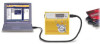
...memory (IC804) was replaced. Note: Do not rewrite the patch data in the personal computer. 3. Click the [Usb Connect] button. 29 MZ-N505 REWRITING THE PATCH DATA AT REPLACEMENT OF MAIN BOARD OR NONVOLATILE MEMORY (IC804) This set requires the patch data in the nonvolatile memory (IC804)... using the application not suitable for Patch Data Rewriting Contact our service technical support division to malfunction. Make sure that the Net MD Driver has been installed in the Test mode. • Rewriting the Patch Data 1. Check the microcomputer version in the Normal mode. Check...
...memory (IC804) was replaced. Note: Do not rewrite the patch data in the personal computer. 3. Click the [Usb Connect] button. 29 MZ-N505 REWRITING THE PATCH DATA AT REPLACEMENT OF MAIN BOARD OR NONVOLATILE MEMORY (IC804) This set requires the patch data in the nonvolatile memory (IC804)... using the application not suitable for Patch Data Rewriting Contact our service technical support division to malfunction. Make sure that the Net MD Driver has been installed in the Test mode. • Rewriting the Patch Data 1. Check the microcomputer version in the Normal mode. Check...

Service Manual
Page 32
... TE 202 ADFG 206 APCREF 174 VC 108 VREF MON OFTRK 26 SW RECON OE RI FI OVER WRITE HEAD DRIVE IC601 (1/2) EFM PRE DRIVER H-BRIDGE PRE DRIVER SYSTEM CONTROL (1/2) 123 56 142 141 140 145 143 EFM 7 CLK 4 VRECIN2 37 VRECIN1 42 C1H CHARGE 28 PUMP 1 C1L 27 C2H CHARGE 31... RST 27 SSB DATA 28 SSB CLK 180 SE 80 PD S0 81 PD S1 SLD MON U SLD MON V SLD MON W TRK+ TRK- FCS+ FCS- MZ-N505 SECTION 6 DIAGRAMS 6-1. TRK+ TRK-
... TE 202 ADFG 206 APCREF 174 VC 108 VREF MON OFTRK 26 SW RECON OE RI FI OVER WRITE HEAD DRIVE IC601 (1/2) EFM PRE DRIVER H-BRIDGE PRE DRIVER SYSTEM CONTROL (1/2) 123 56 142 141 140 145 143 EFM 7 CLK 4 VRECIN2 37 VRECIN1 42 C1H CHARGE 28 PUMP 1 C1L 27 C2H CHARGE 31... RST 27 SSB DATA 28 SSB CLK 180 SE 80 PD S0 81 PD S1 SLD MON U SLD MON V SLD MON W TRK+ TRK- FCS+ FCS- MZ-N505 SECTION 6 DIAGRAMS 6-1. TRK+ TRK-

Service Manual
Page 34
...(IC301), SYSTEM CONTROLLER (IC801), EEPROM (IC804) B+ VA A/D CONVERTER (IC301), SYSTEM CONTROLLER (IC801) B+ VC RF AMP (IC501), MOTOR/COIL DRIVER (IC551), REMOTE CONTROL CIRCUIT B+ NOISE FILTER NOISE FILTER VRECO OVER WRITE HEAD DRIVE (IC601) B+ VREC OVER WRITE HEAD DRIVE CIRCUIT B+ L904 ... CHARGE MONITOR GAIN 54 55 CHG SYSTEM CONTROL (2/2) SWITCHING REGULATOR L1 1 11 L1 2 14 STEP-UP DOWN PRE DRIVER & DW BT DW TP 22 21 PWM VIO 8 VC2 26 VC 9 VG 36 BATTERY CHARGER & REGULATOR RF2... T601 TH601 J601 DC IN 3V - + GROUND LINE SWITCHING Q601 34 34 BLOCK DIAGRAM - MZ-N505 6-3.
...(IC301), SYSTEM CONTROLLER (IC801), EEPROM (IC804) B+ VA A/D CONVERTER (IC301), SYSTEM CONTROLLER (IC801) B+ VC RF AMP (IC501), MOTOR/COIL DRIVER (IC551), REMOTE CONTROL CIRCUIT B+ NOISE FILTER NOISE FILTER VRECO OVER WRITE HEAD DRIVE (IC601) B+ VREC OVER WRITE HEAD DRIVE CIRCUIT B+ L904 ... CHARGE MONITOR GAIN 54 55 CHG SYSTEM CONTROL (2/2) SWITCHING REGULATOR L1 1 11 L1 2 14 STEP-UP DOWN PRE DRIVER & DW BT DW TP 22 21 PWM VIO 8 VC2 26 VC 9 VG 36 BATTERY CHARGER & REGULATOR RF2... T601 TH601 J601 DC IN 3V - + GROUND LINE SWITCHING Q601 34 34 BLOCK DIAGRAM - MZ-N505 6-3.

Service Manual
Page 47
... 17 PGND2 16 L2 15 NC VLON XWK1 XWK2 XWK3 XWK4 VSTB VRMC GND VL VLO VL L2 PGND2 PGND2 47 STEP-UP PRE DRIVER PWM + - IC901 XPC18A32FCR2 MZ-N505 VIF VA VAFB VDFB VIFFB GND VC VCO VC VC OUT L1 NC PGND1 PGND1 NC 43 VD 44 VC2 45 42 41... 54 SLEEP 55 CLK 56 VSTB VC VB SYSTEM CONTROL VSTB VC BANDGAP REFERENCE VC PWM VG VG VB VC POWER SWITCH 2 STEP-UP PRE DRIVER FFCLR OUTPUT SW 33 32 31 30 29 OUTPUT SW VC + -
... 17 PGND2 16 L2 15 NC VLON XWK1 XWK2 XWK3 XWK4 VSTB VRMC GND VL VLO VL L2 PGND2 PGND2 47 STEP-UP PRE DRIVER PWM + - IC901 XPC18A32FCR2 MZ-N505 VIF VA VAFB VDFB VIFFB GND VC VCO VC VC OUT L1 NC PGND1 PGND1 NC 43 VD 44 VC2 45 42 41... 54 SLEEP 55 CLK 56 VSTB VC VB SYSTEM CONTROL VSTB VC BANDGAP REFERENCE VC PWM VG VG VB VC POWER SWITCH 2 STEP-UP PRE DRIVER FFCLR OUTPUT SW 33 32 31 30 29 OUTPUT SW VC + -

Service Manual
Page 50
...70 CS RTC O Chip select signal output terminal Not used 71 XCS NV1 O Chip select signal (1) output to the nonvolatile memory 72 IFVDD1 - MZ-N505 Pin No. 56 Pin Name KDI I/O I Data input terminal Not used Description 57 TRST I Input terminal for the test mode set (normally ...microcomputer I/F block) 96 IFVDD2 - Ground terminal (for the microcomputer I/F block) 74 XRST MTR DRV O Reset control signal output to the motor driver "L": reset 75 XRF RST O Reset control signal output to the RF amplifier "L": reset 76 SPDL MON I Spindle servo monitor signal input terminal ...
...70 CS RTC O Chip select signal output terminal Not used 71 XCS NV1 O Chip select signal (1) output to the nonvolatile memory 72 IFVDD1 - MZ-N505 Pin No. 56 Pin Name KDI I/O I Data input terminal Not used Description 57 TRST I Input terminal for the test mode set (normally ...microcomputer I/F block) 96 IFVDD2 - Ground terminal (for the microcomputer I/F block) 74 XRST MTR DRV O Reset control signal output to the motor driver "L": reset 75 XRF RST O Reset control signal output to the RF amplifier "L": reset 76 SPDL MON I Spindle servo monitor signal input terminal ...

Service Manual
Page 53
Ground terminal (for the DSP block) - MZ-N505 Pin No. 199 200 201 202 203 204 205 ...XBCKI/ECK DATAI/EDT XERQ A11 XOE XWE TSTDR3 I/O Description I Sled motor drive comparison signal input (W) from the motor driver - Power supply terminal (for D-RAM Not used - Ground terminal (for the microcomputer I/F block) O EFM encode data...the DSP block) (+1.5V) I Sled motor drive comparison signal input (U) from the motor driver I Sled motor drive comparison signal input (V) from the motor driver I Ground terminal Clock signal input from the external VCO Not used I Spindle motor drive...
Ground terminal (for the DSP block) - MZ-N505 Pin No. 199 200 201 202 203 204 205 ...XBCKI/ECK DATAI/EDT XERQ A11 XOE XWE TSTDR3 I/O Description I Sled motor drive comparison signal input (W) from the motor driver - Power supply terminal (for D-RAM Not used - Ground terminal (for the microcomputer I/F block) O EFM encode data...the DSP block) (+1.5V) I Sled motor drive comparison signal input (U) from the motor driver I Sled motor drive comparison signal input (V) from the motor driver I Ground terminal Clock signal input from the external VCO Not used I Spindle motor drive...

