
Operating Instructions
Page 2
... Panel 5 Rear Panel 9 Status Display Window (MKS-R1630 10 Preparations 15 Notes on Installation 15 Configuring Using a System Controller and Web Menu 15 Setting Up the Unit 15 Configuring Using the Buttons 17 Operations 18 Switching between source selection mode and destination selection mode 18 Switching Crosspoints 18 Assigning Functions to Selection Buttons (Assign) .......19 Switching a Different Source for Each Level (Breakaway 20 Switching Multiple Crosspoints Simultaneously (Salvo 21 Pages and Page Groups...
... Panel 5 Rear Panel 9 Status Display Window (MKS-R1630 10 Preparations 15 Notes on Installation 15 Configuring Using a System Controller and Web Menu 15 Setting Up the Unit 15 Configuring Using the Buttons 17 Operations 18 Switching between source selection mode and destination selection mode 18 Switching Crosspoints 18 Assigning Functions to Selection Buttons (Assign) .......19 Switching a Different Source for Each Level (Breakaway 20 Switching Multiple Crosspoints Simultaneously (Salvo 21 Pages and Page Groups...
Operating Instructions
Page 3
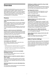
... front panel designed for each type of each button. System redundancy support The unit features dual power supplies and networks to a button upon your merely pressing that display functions in the display window. Status display function using the web menu. You can be used as either source selection buttons or destination selection buttons. Features Large buttons that button. 3 Controllable up green or amber, dimly or brightly to each selection button (MKS-R1620/R1630...
... front panel designed for each type of each button. System redundancy support The unit features dual power supplies and networks to a button upon your merely pressing that display functions in the display window. Status display function using the web menu. You can be used as either source selection buttons or destination selection buttons. Features Large buttons that button. 3 Controllable up green or amber, dimly or brightly to each selection button (MKS-R1620/R1630...

Operating Instructions
Page 5
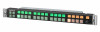
... are disabled. This prevents undesired switching caused by accidental touching of Parts Front Panel MKS-R3210/R1620 MKS-R3210 a STATS button/lamp b MONI button/lamp c Preset display window MKS-R1620 e LOCK (CHOP) button/lamp d PROT button/lamp f Source/destination selection buttons g Selector knob h ASSGN button/lamp i DEST button/lamp j Display window c Preset display window e LOCK (CHOP) button/lamp d PROT button/lamp f Source/destination selection buttons g Selector knob a STATS (status) button/lamp Flashes red when an error...
... are disabled. This prevents undesired switching caused by accidental touching of Parts Front Panel MKS-R3210/R1620 MKS-R3210 a STATS button/lamp b MONI button/lamp c Preset display window MKS-R1620 e LOCK (CHOP) button/lamp d PROT button/lamp f Source/destination selection buttons g Selector knob h ASSGN button/lamp i DEST button/lamp j Display window c Preset display window e LOCK (CHOP) button/lamp d PROT button/lamp f Source/destination selection buttons g Selector knob a STATS (status) button/lamp Flashes red when an error...
Operating Instructions
Page 6
... any problem caused by the knob being accidentally pressed, the function that the selected crosspoint has been switched, and then the button lights up bright amber. In status display mode, the system checks that is activated when this button (top left button) lights up bright green. On the MKS-R1620, this knob is displayed in the web menu, source (input) selection buttons are lit dim green, and...
... any problem caused by the knob being accidentally pressed, the function that the selected crosspoint has been switched, and then the button lights up bright amber. In status display mode, the system checks that is activated when this button (top left button) lights up bright green. On the MKS-R1620, this knob is displayed in the web menu, source (input) selection buttons are lit dim green, and...

Operating Instructions
Page 7
... software is reset. When you press this unit. 7 For details about button function settings, see "Display transition" (page 14). For details about the content displayed in the status display window, see "Pages and Page Groups" (page 22). For details about switching pages and groups, see "Status Display Window (MKS-R1630)" (page 10). f Selection buttons These buttons can configure the type of selection of the status display window is disabled...
... software is reset. When you press this unit. 7 For details about button function settings, see "Display transition" (page 14). For details about the content displayed in the status display window, see "Pages and Page Groups" (page 22). For details about switching pages and groups, see "Status Display Window (MKS-R1630)" (page 10). f Selection buttons These buttons can configure the type of selection of the status display window is disabled...

Operating Instructions
Page 15
... the source/destination selection buttons. For details about network preferences, refer to each button. Then you have assigned to the Installation Manual. Use the web menu to display the web menu. Making a key label 1 Copy the key label guide shown below onto a sheet of cables add to vibration shock to the connector on the [Salvo Table] page (page 26). Settings using the system controller and web menu. Preparations Notes...
... the source/destination selection buttons. For details about network preferences, refer to each button. Then you have assigned to the Installation Manual. Use the web menu to display the web menu. Making a key label 1 Copy the key label guide shown below onto a sheet of cables add to vibration shock to the connector on the [Salvo Table] page (page 26). Settings using the system controller and web menu. Preparations Notes...

Operating Instructions
Page 17
... button cap with the key-top puller and remove the button. For details about the key-cap puller (part number: 4-592-03601), consult your Sony representative. For details about the IP address setting, refer to the buttons using the web menu, but the following items can also be set on the unit by default on the unit. Setting the default IP address Simultaneously press buttons 1 and 2, then turn the power on the button...
... button cap with the key-top puller and remove the button. For details about the key-cap puller (part number: 4-592-03601), consult your Sony representative. For details about the IP address setting, refer to the buttons using the web menu, but the following items can also be set on the unit by default on the unit. Setting the default IP address Simultaneously press buttons 1 and 2, then turn the power on the button...
Operating Instructions
Page 18
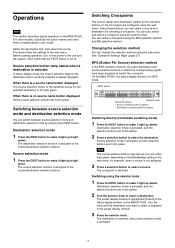
... the system. Using these buttons, you can select a source and destination for the selection buttons on the MKS-R1620. See "Operation Settings Page" (page 27). BPS (Button Per Source) selection method In the BPS selection method, you want to select is activated, and the selection buttons are lit dim amber. 2 Turn the selector knob to your model. Destination selection mode is switched. Note...
... the system. Using these buttons, you can select a source and destination for the selection buttons on the MKS-R1620. See "Operation Settings Page" (page 27). BPS (Button Per Source) selection method In the BPS selection method, you want to select is activated, and the selection buttons are lit dim amber. 2 Turn the selector knob to your model. Destination selection mode is switched. Note...

Operating Instructions
Page 19
... switched in the preset display window ([Preset] in the status display window on the pressed button is switched. When you want to set in the preset display window ([Preset] in the web menu. The crosspoint set on the MKS-R1630). 2 Press the selector knob. The crosspoint of the source you press the DEST button, and the buttons light up amber, destinations are configured using the selector knob 1 Turn...
... switched in the preset display window ([Preset] in the status display window on the pressed button is switched. When you want to set in the preset display window ([Preset] in the web menu. The crosspoint set on the MKS-R1630). 2 Press the selector knob. The crosspoint of the source you press the DEST button, and the buttons light up amber, destinations are configured using the selector knob 1 Turn...

Operating Instructions
Page 20
... when a single source is not used , the display of the selected level: IN16 (bright green) Note Buttons may light up red. Switching a Different Source for Each Level (Breakaway) When switching sources, a different source can be assigned to a function button beforehand using the web menu. 1 Press the SHIFT button. 2 Press the DEST button to set level selection mode. MKS-R1620 DEST button Level display LV1 LV2 LV3...
... when a single source is not used , the display of the selected level: IN16 (bright green) Note Buttons may light up red. Switching a Different Source for Each Level (Breakaway) When switching sources, a different source can be assigned to a function button beforehand using the web menu. 1 Press the SHIFT button. 2 Press the DEST button to set level selection mode. MKS-R1620 DEST button Level display LV1 LV2 LV3...
Operating Instructions
Page 21
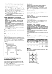
... be set a pair of crosspoints (multiple audio channels, video key signal, for one level is selected. Executing a salvo Press the selection button on the left. On the MKS-R1620, levels are assigned to different levels, and the type of signal to switch is controlled using the level function. Enabled level selection buttons are all switched. On the MKS-R1630, the four selection buttons on the [Default Control] page...
... be set a pair of crosspoints (multiple audio channels, video key signal, for one level is selected. Executing a salvo Press the selection button on the left. On the MKS-R1620, levels are assigned to different levels, and the type of signal to switch is controlled using the level function. Enabled level selection buttons are all switched. On the MKS-R1630, the four selection buttons on the [Default Control] page...
Operating Instructions
Page 24
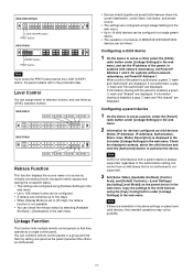
... web menu. You can combine remote control panels in a group and link them as parent/child devices share the current destination, control level, lock status, and preset source. • The settings are configured using the [Copy Config] button under [Linkage Settings] in the web menu. On systems without network redundancy, set Parent IP Address 1 and 2. Copy the settings to 10 child devices can be configure for devices configured as a single control panel. MKS-R3210/R1620 LOCK (CHOP) button PROT button MKS...
... web menu. You can combine remote control panels in a group and link them as parent/child devices share the current destination, control level, lock status, and preset source. • The settings are configured using the [Copy Config] button under [Linkage Settings] in the web menu. On systems without network redundancy, set Parent IP Address 1 and 2. Copy the settings to 10 child devices can be configure for devices configured as a single control panel. MKS-R3210/R1620 LOCK (CHOP) button PROT button MKS...
Operating Instructions
Page 25
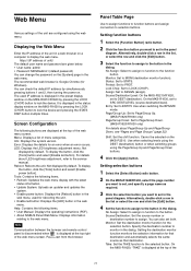
... latest status information. • Update System: Uploads an updater and updates the system. • Enable power button: Displays the [Reboot] button in the panel diagram. Lock Chop: Set to set in the web menu, used IP address is displayed at the top of the web menu screen. Setting selection buttons 1 Select the [Select Button] radio button. 2 On the MKS-R1620/R1630, select the page number you want to set in the dialog. You can change the password...
... latest status information. • Update System: Uploads an updater and updates the system. • Enable power button: Displays the [Reboot] button in the panel diagram. Lock Chop: Set to set in the web menu, used IP address is displayed at the top of the web menu screen. Setting selection buttons 1 Select the [Select Button] radio button. 2 On the MKS-R1620/R1630, select the page number you want to set in the dialog. You can change the password...

Operating Instructions
Page 27
.... Select this mode if a problem would occur if any one location does not switch. Multi: Multiple levels can be selected. Note When [Protect Mode] is enabled on MKS-R1630) Select the Take operation for sources or destinations, respectively. BPS/MD Take Mode (Enabled only on the MKS-R1620/R1630 only. Default Controls Page Use to enable local protection, salvo switching is protected. When a selected button is pressed...
.... Select this mode if a problem would occur if any one location does not switch. Multi: Multiple levels can be selected. Note When [Protect Mode] is enabled on MKS-R1630) Select the Take operation for sources or destinations, respectively. BPS/MD Take Mode (Enabled only on the MKS-R1620/R1630 only. Default Controls Page Use to enable local protection, salvo switching is protected. When a selected button is pressed...
Operating Instructions
Page 29
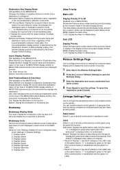
... number if multiple sources exist. Alias Priority Main LCD Display Priority #1 to five connector names can combine remote control panels in the MKS-R1620 display window or MKS-R1630 selection button, this sets which line displays the destination. Retrace Settings Page Use to configure the function for tracing the crosspoint status display and to display the source names of buttons when a different source is selected in [Destination Key...
... number if multiple sources exist. Alias Priority Main LCD Display Priority #1 to five connector names can combine remote control panels in the MKS-R1620 display window or MKS-R1630 selection button, this sets which line displays the destination. Retrace Settings Page Use to configure the function for tracing the crosspoint status display and to display the source names of buttons when a different source is selected in [Destination Key...

Operating Instructions
Page 30
... address: IP address Subnet mask: Subnet mask Default gateway: Default gateway System Controller: IP address of system controller Ntp Server: IP address of traps. Note Control of child devices from a parent device is set to send traps. 30 Setting a page group 1 Double-click a group number to the network. Remote Maintenance Page Use to configure settings related to [Specific]. The Salvo Table, Available Src/Dest, and Control Area items are settings for the LAN on the [Panel Table] page as the parent when using DHCP...
... address: IP address Subnet mask: Subnet mask Default gateway: Default gateway System Controller: IP address of system controller Ntp Server: IP address of traps. Note Control of child devices from a parent device is set to send traps. 30 Setting a page group 1 Double-click a group number to the network. Remote Maintenance Page Use to configure settings related to [Specific]. The Salvo Table, Available Src/Dest, and Control Area items are settings for the LAN on the [Panel Table] page as the parent when using DHCP...

Operating Instructions
Page 31
... admin user for accessing the web menu. System Settings Name: Enter the name of DC IN power supply errors. Restore: Restore the saved settings status from a web browser. Password Settings Use to set correctly on the [Network Settings] page. New Password: Enter the new password. Verify: Enter the new password again. Notes • Changed passwords are restored to the default state. • The network settings of the remote control panel are confirmed. Time Settings Page Use to configure settings related to the backup region. Export/Import settings Export: Download...
... admin user for accessing the web menu. System Settings Name: Enter the name of DC IN power supply errors. Restore: Restore the saved settings status from a web browser. Password Settings Use to set correctly on the [Network Settings] page. New Password: Enter the new password. Verify: Enter the new password again. Notes • Changed passwords are restored to the default state. • The network settings of the remote control panel are confirmed. Time Settings Page Use to configure settings related to the backup region. Export/Import settings Export: Download...
Operating Instructions
Page 32
... to access the unit. These problems are not a malfunction. Since the login status remains in the Web browser while making settings or after making settings. If usage exceeds the above normal usage frequency, the life expectancy may damage the unit. From a safety standpoint, when using the unit or harmful programs from the factory preset values (page 31). Changing the password regularly...
... to access the unit. These problems are not a malfunction. Since the login status remains in the Web browser while making settings or after making settings. If usage exceeds the above normal usage frequency, the life expectancy may damage the unit. From a safety standpoint, when using the unit or harmful programs from the factory preset values (page 31). Changing the password regularly...
Operating Instructions
Page 33
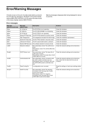
...link is unknown. Redundancy mode: The required information from the lease file of LAN1 could not be loaded. Started PF Recovery The PIF FPGA started in recovery mode. Reset the settings or load a user settings status file. Check the hardware. Check the network settings and connections. Redundancy mode: The lease files of LAN1 does not exist. Panel Config Err A configuration error occurred. Unknown KY Board The KY board model name is down . Started SW Recovery The software started in recovery mode. Check the network settings and connections. Check the network...
...link is unknown. Redundancy mode: The required information from the lease file of LAN1 could not be loaded. Started PF Recovery The PIF FPGA started in recovery mode. Reset the settings or load a user settings status file. Check the hardware. Check the network settings and connections. Redundancy mode: The lease files of LAN1 does not exist. Panel Config Err A configuration error occurred. Unknown KY Board The KY board model name is down . Started SW Recovery The software started in recovery mode. Check the network settings and connections. Check the network...

Operating Instructions
Page 34
...device when panel link is down . Time Sync Err A time synchronization error occurred. Check the network settings and connections. Check the network settings and connections. LAN2 Linkdown Non-redundancy mode: This error does not Check the network settings and connections. Redundancy mode: Could not connect to the DC Check the DC power supply. LAN1 DHCP Srv Lost The lease file of LAN1 does not exist. Check the network settings and connections. Redundancy mode: The LAN2 lease file does not exist. Check the network settings and connections. Check the network settings...
...device when panel link is down . Time Sync Err A time synchronization error occurred. Check the network settings and connections. Check the network settings and connections. LAN2 Linkdown Non-redundancy mode: This error does not Check the network settings and connections. Redundancy mode: Could not connect to the DC Check the DC power supply. LAN1 DHCP Srv Lost The lease file of LAN1 does not exist. Check the network settings and connections. Redundancy mode: The LAN2 lease file does not exist. Check the network settings and connections. Check the network settings...