Operating Instructions
Page 2
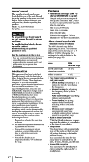
... and 15 min. • Stereo FM reception You can fall asleep listening to the radio without worry. If this equipment. Connect the equipment into the station of your choice at ...stations automatically. - Model No. ICF-SW7600GR Serial No Warning To prevent fire or shock hazard, do not open the cabinet. Refer servicing to suit your Sony dealer regarding this unit is no... to correct the interference by directly specifying the frequency. - Reorient or relocate the receiving antenna. - Owner's record The model and serial numbers are designed to provide reasonable protection against...
... and 15 min. • Stereo FM reception You can fall asleep listening to the radio without worry. If this equipment. Connect the equipment into the station of your choice at ...stations automatically. - Model No. ICF-SW7600GR Serial No Warning To prevent fire or shock hazard, do not open the cabinet. Refer servicing to suit your Sony dealer regarding this unit is no... to correct the interference by directly specifying the frequency. - Reorient or relocate the receiving antenna. - Owner's record The model and serial numbers are designed to provide reasonable protection against...
Operating Instructions
Page 3
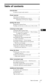
... frequency - Synchronous detection 27 Using the timer Waking up to the radio - Hold function ....... 32 Recording broadcasts 33 Using the supplied SW external antenna 34 Using the optional external antenna 35 Additional information Precautions and maintenance 36 Troubleshooting 38 Specifications 40 Tips ...and controls 4 Power sources Operating on batteries 8 Operating on external power sources 10 Operating on radio waves 41 Table of the world ... 13 Listening to the radio Changing MW Channel Step 15 GB Directly entering the frequency - Standby function 28 Falling asleep ...
... frequency - Synchronous detection 27 Using the timer Waking up to the radio - Hold function ....... 32 Recording broadcasts 33 Using the supplied SW external antenna 34 Using the optional external antenna 35 Additional information Precautions and maintenance 36 Troubleshooting 38 Specifications 40 Tips ...and controls 4 Power sources Operating on batteries 8 Operating on external power sources 10 Operating on radio waves 41 Table of the world ... 13 Listening to the radio Changing MW Channel Step 15 GB Directly entering the frequency - Standby function 28 Falling asleep ...
Operating Instructions
Page 4
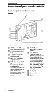
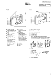
... 10 seconds. When using headphones, sound from the speaker will extend the lighting time. 8 Display (7) 9 Controls (6) 0 Speaker 4GB Introduction Front 1 AM EXT ANT (AM external antenna) jack (35) 2 ATT (attenuator) control (21) 3 ATT (attenuator) ON/ OFF switch (21) 4 LINE OUT (recording output) jack (33) 5 2 (headphones) jack (17, 33) You can enjoy...
... 10 seconds. When using headphones, sound from the speaker will extend the lighting time. 8 Display (7) 9 Controls (6) 0 Speaker 4GB Introduction Front 1 AM EXT ANT (AM external antenna) jack (35) 2 ATT (attenuator) control (21) 3 ATT (attenuator) ON/ OFF switch (21) 4 LINE OUT (recording output) jack (33) 5 2 (headphones) jack (17, 33) You can enjoy...
Operating Instructions
Page 5
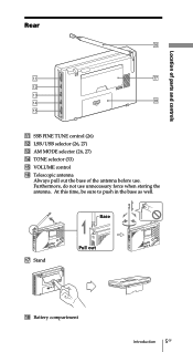
Rear Location of parts and controls qa SSB FINE TUNE control (26) qs LSB/USB selector (26, 27) qd AM MODE selector (26, 27) qf TONE selector (33) qg VOLUME control qh Telescopic antenna Always pull out the base of the antenna before use unnecessary force when storing the antenna. Base qj Stand Pull out qk Battery compartment Introduction 5GB At this time, be sure to push in the base as well. Furthermore, do not use .
Rear Location of parts and controls qa SSB FINE TUNE control (26) qs LSB/USB selector (26, 27) qd AM MODE selector (26, 27) qf TONE selector (33) qg VOLUME control qh Telescopic antenna Always pull out the base of the antenna before use unnecessary force when storing the antenna. Base qj Stand Pull out qk Battery compartment Introduction 5GB At this time, be sure to push in the base as well. Furthermore, do not use .
Operating Instructions
Page 17
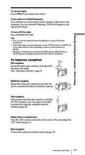
...even better reception by the built-in ferrite bar antenna. SW reception Fully extend the telescopic antenna vertically. If you enter an invalid frequency You will hear two short beeps and the display will return to the radio 17GB When listening to music, set the TONE ...the frequency and repeat from Step 3. To improve reception FM reception Extend the telescopic antenna, and adjust the direction and angle. (See "telescopic antenna", page 5) MW/LW reception Retract the telescopic antenna and rotate the unit to internal spurious signals generated by using the supplied external...
...even better reception by the built-in ferrite bar antenna. SW reception Fully extend the telescopic antenna vertically. If you enter an invalid frequency You will hear two short beeps and the display will return to the radio 17GB When listening to music, set the TONE ...the frequency and repeat from Step 3. To improve reception FM reception Extend the telescopic antenna, and adjust the direction and angle. (See "telescopic antenna", page 5) MW/LW reception Retract the telescopic antenna and rotate the unit to internal spurious signals generated by using the supplied external...
Operating Instructions
Page 34
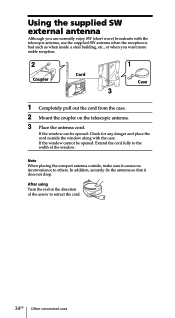
...when you want more stable reception. 2 Coupler Cord 1 Case 3 1 Completely pull out the cord from the case. 2 Mount the coupler on the telescopic antenna. 3 Place the antenna cord. In addition, securely fix the antenna so that it causes no inconvenience to retract the cord. 34GB Other convenient uses Using the supplied SW external... antenna Although you can be opened : Check for any danger and place the cord outside , make sure it does not drop. After using Turn the reel...
...when you want more stable reception. 2 Coupler Cord 1 Case 3 1 Completely pull out the cord from the case. 2 Mount the coupler on the telescopic antenna. 3 Place the antenna cord. In addition, securely fix the antenna so that it causes no inconvenience to retract the cord. 34GB Other convenient uses Using the supplied SW external... antenna Although you can be opened : Check for any danger and place the cord outside , make sure it does not drop. After using Turn the reel...
Operating Instructions
Page 35
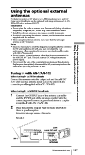
...AN-1/AN-102 When tuning in to MW/LW broadcasts 1 Connect the OUTPUT jack of the antenna controller and the INPUT jack of the radio with AN-1/AN-102). 2 Place the antenna coupler near fluorescent lighting, televisions, telephones, computers, etc., as this may not obtain the ...supplied SW (short wave) external antenna Using the optional external antennas Using the optional external antennas For better reception of the radio. When tuning in to INPUT (MW/LW) Other convenient uses 35GB Installation • Do not place the radio or antenna near the radio and where there is fully ...
...AN-1/AN-102 When tuning in to MW/LW broadcasts 1 Connect the OUTPUT jack of the antenna controller and the INPUT jack of the radio with AN-1/AN-102). 2 Place the antenna coupler near fluorescent lighting, televisions, telephones, computers, etc., as this may not obtain the ...supplied SW (short wave) external antenna Using the optional external antennas Using the optional external antennas For better reception of the radio. When tuning in to INPUT (MW/LW) Other convenient uses 35GB Installation • Do not place the radio or antenna near the radio and where there is fully ...
Operating Instructions
Page 36
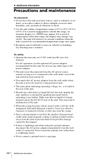
... Do not use any other type of AC power adaptor. • The unit is not disconnected from the wall outlet, if connected. Never touch the antenna wire when there is located at the rear of the unit. • When the casing becomes soiled, clean it is connected to malfunction of the... is used in temperatures below this unit. Never use the optional AC power adaptor recommended for the speaker, keep personal credit cards using the external antenna, disconnect the AC power adaptor immediately from the AC power source (mains) as long as they may lead to the wall outlet, even if the...
... Do not use any other type of AC power adaptor. • The unit is not disconnected from the wall outlet, if connected. Never touch the antenna wire when there is located at the rear of the unit. • When the casing becomes soiled, clean it is connected to malfunction of the... is used in temperatures below this unit. Never use the optional AC power adaptor recommended for the speaker, keep personal credit cards using the external antenna, disconnect the AC power adaptor immediately from the AC power source (mains) as long as they may lead to the wall outlet, even if the...
Operating Instructions
Page 38
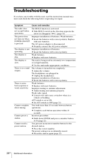
...conditions. c Insert the batteries with correct polarity. You pressed an incorrect number button for repair. Symptom Cause and remedies The radio does not accept button operations. There is being used in extremely low temperature or in a vehicle or building. Cannot complete ... 10 seconds. c Preset the station again (page 22). 38GB Additional information Weak batteries. c Adjust the volume. Improper tuning or antenna adjustment. c Hold down completely. c Press the correct number. Troubleshooting If you have any trouble with the unit, read the instruction...
...conditions. c Insert the batteries with correct polarity. You pressed an incorrect number button for repair. Symptom Cause and remedies The radio does not accept button operations. There is being used in extremely low temperature or in a vehicle or building. Cannot complete ... 10 seconds. c Preset the station again (page 22). 38GB Additional information Weak batteries. c Adjust the volume. Improper tuning or antenna adjustment. c Hold down completely. c Press the correct number. Troubleshooting If you have any trouble with the unit, read the instruction...
Operating Instructions
Page 40
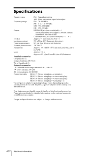
... parts (w/h/d) Mass Approx. 536 g Approx. 608 g (incl. four R6 (size AA) batteries) Supplied accessories Carrying case (1) Compact antenna AN-71 (1) Wave Handbook (1) Optional accessories LW/MW/SW wide range antenna AN-1, AN-102 SW active antenna AN-LP1 AC power adopter AC-E60HG Connecting cable RK-G135 (Stereo miniplug y miniplug) RK-G134 (Stereo...
... parts (w/h/d) Mass Approx. 536 g Approx. 608 g (incl. four R6 (size AA) batteries) Supplied accessories Carrying case (1) Compact antenna AN-71 (1) Wave Handbook (1) Optional accessories LW/MW/SW wide range antenna AN-1, AN-102 SW active antenna AN-LP1 AC power adopter AC-E60HG Connecting cable RK-G135 (Stereo miniplug y miniplug) RK-G134 (Stereo...
Service Manual
Page 1
four R6 (size AA) batteries) Supplied accessories Carrying case (1) Compact antenna AN-71 (1) Wave Handbook (1) Design and specifications are subject to change without notice. 9-873-099-11 2001C1600-1 © 2001.3 Sony Corporation Audio Entertainment Group General Engineering Dept. ICF-SW7600GR SERVICE MANUAL Ver 1.0 2001. 03 US Model Canadian Model AEP Model Chinese Model E Model Tourist...
four R6 (size AA) batteries) Supplied accessories Carrying case (1) Compact antenna AN-71 (1) Wave Handbook (1) Design and specifications are subject to change without notice. 9-873-099-11 2001C1600-1 © 2001.3 Sony Corporation Audio Entertainment Group General Engineering Dept. ICF-SW7600GR SERVICE MANUAL Ver 1.0 2001. 03 US Model Canadian Model AEP Model Chinese Model E Model Tourist...
Service Manual
Page 3
Furthermore, do not use . Base qj Stand Pull out qk Battery compartment 3 Front SECTION 1 GENERAL Rear ICF-SW7600GR This section is extracted from the speaker will be muted. 6 DC IN 6V ! (external power input) jack (10) 7 LIGHT button When the display... selector (26, 27) qf TONE selector (33) qg VOLUME control qh Telescopic antenna Always pull out the base of the antenna before use unnecessary force when storing the antenna. When using headphones, sound from instruction manual. 1 AM EXT ANT (AM external antenna) jack (35) 2 ATT (attenuator) control (21) 3 ATT (attenuator) ON/ ...
Furthermore, do not use . Base qj Stand Pull out qk Battery compartment 3 Front SECTION 1 GENERAL Rear ICF-SW7600GR This section is extracted from the speaker will be muted. 6 DC IN 6V ! (external power input) jack (10) 7 LIGHT button When the display... selector (26, 27) qf TONE selector (33) qg VOLUME control qh Telescopic antenna Always pull out the base of the antenna before use unnecessary force when storing the antenna. When using headphones, sound from instruction manual. 1 AM EXT ANT (AM external antenna) jack (35) 2 ATT (attenuator) control (21) 3 ATT (attenuator) ON/ ...
Service Manual
Page 6
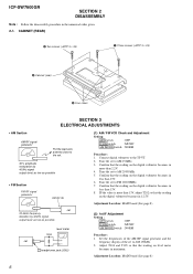
...BTP 3 × 25) 4 Cabinet (rear) 3 Four claws SECTION 3 ELECTRICAL ADJUSTMENTS • AM Section AM RF signal generator Put the lead-wire antenna close to the set. 30% amplitude modulation by 400Hz signal output level: as low as possible • FM Section FM RF signal generator FM RF...as low as possible 16 Ω level meter set to AM 29999kHz. 5. Confirm that the reading on the digital voltmeter becomes in 12.5V. ICF-SW7600GR SECTION 2 DISASSEMBLY Note : Follow the disassembly procedure in maximum. Tune the set i headphones jack (J202) (1) AM / FM VCO Check and...
...BTP 3 × 25) 4 Cabinet (rear) 3 Four claws SECTION 3 ELECTRICAL ADJUSTMENTS • AM Section AM RF signal generator Put the lead-wire antenna close to the set. 30% amplitude modulation by 400Hz signal output level: as low as possible • FM Section FM RF signal generator FM RF...as low as possible 16 Ω level meter set to AM 29999kHz. 5. Confirm that the reading on the digital voltmeter becomes in 12.5V. ICF-SW7600GR SECTION 2 DISASSEMBLY Note : Follow the disassembly procedure in maximum. Tune the set i headphones jack (J202) (1) AM / FM VCO Check and...
Service Manual
Page 10
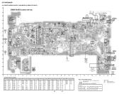
... T102 G K T202 D K S CT101 A T101 C135 K X201 B A E C A K TP OSC2 TP SD C 30 E BA CT202 C K E E BC B C221 8 C262 C260 C261 C259 9 ANT101 FM/SW TELESCOPIC ANTENNA ANT102 MW/LW FERRITE-ROD ANTENNA UNPLUGGED PLUGGED CH C121 ORG GRN BLK PNK EB T106 S B G D E C A A KK C C128 S K T103 D GA K C157 A G S C146 D E C E C B E C BE E C B C B B C G EA S D T107 K C152 CN201 ...No. Location Ref. No. No. No. No. Parts on the parts face side seen from the pattern face are indicated. Location Ref. Location Ref. ICF-SW7600GR 4-2.
... T102 G K T202 D K S CT101 A T101 C135 K X201 B A E C A K TP OSC2 TP SD C 30 E BA CT202 C K E E BC B C221 8 C262 C260 C261 C259 9 ANT101 FM/SW TELESCOPIC ANTENNA ANT102 MW/LW FERRITE-ROD ANTENNA UNPLUGGED PLUGGED CH C121 ORG GRN BLK PNK EB T106 S B G D E C A A KK C C128 S K T103 D GA K C157 A G S C146 D E C E C B E C BE E C B C B B C G EA S D T107 K C152 CN201 ...No. Location Ref. No. No. No. No. Parts on the parts face side seen from the pattern face are indicated. Location Ref. Location Ref. ICF-SW7600GR 4-2.
Service Manual
Page 16
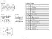
...supply (+3V) O Pin for connecting crystal resonator for system clock I Key input protect switch signal input O Radio power control signal output O AM/FM select signal output O Bar/Rod antenna select signal output - Pin for capacitor connection for oscillation circuit O LCD drive voltage output - Pin for ...voltage - IN2 NC NC NF2 GND2 P-GND2 OUT RIPPLE IN1 REG VOL NF1 GND1 P-GND1 OUT1 VCC R L M/ST STLED GND NC IN NC NC ICF-SW7600GR • IC BLOCK DIAGRAMS IC201 CXA1376AS IC202 LA3335M 10 9 DECODER 8 SYNC DET 7 6 LAMP TRIGGER STEREO SWITCH FF 90º FF 1/2 FF 0&#...
...supply (+3V) O Pin for connecting crystal resonator for system clock I Key input protect switch signal input O Radio power control signal output O AM/FM select signal output O Bar/Rod antenna select signal output - Pin for capacitor connection for oscillation circuit O LCD drive voltage output - Pin for ...voltage - IN2 NC NC NF2 GND2 P-GND2 OUT RIPPLE IN1 REG VOL NF1 GND1 P-GND1 OUT1 VCC R L M/ST STLED GND NC IN NC NC ICF-SW7600GR • IC BLOCK DIAGRAMS IC201 CXA1376AS IC202 LA3335M 10 9 DECODER 8 SYNC DET 7 6 LAMP TRIGGER STEREO SWITCH FF 90º FF 1/2 FF 0&#...
Service Manual
Page 17
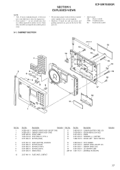
...-11 FOOT, RUBBER CABINET (REAR) (EXCEPT CH) CABINET (REAR) (CH) LID, BATTERY CASE ANTENNA, TELESCOPIC 10 3-227-401-01 PLATE (ANT), CONTACT Remarks 17 No. 11 12 13 14 15 Part No. No. 1 1 2 3 4 Part No. SECTION 5 EXPLODED VIEWS ICF-SW7600GR NOTE: • -XX, -X mean standardized parts, so they may have some differences from...
...-11 FOOT, RUBBER CABINET (REAR) (EXCEPT CH) CABINET (REAR) (CH) LID, BATTERY CASE ANTENNA, TELESCOPIC 10 3-227-401-01 PLATE (ANT), CONTACT Remarks 17 No. 11 12 13 14 15 Part No. No. 1 1 2 3 4 Part No. SECTION 5 EXPLODED VIEWS ICF-SW7600GR NOTE: • -XX, -X mean standardized parts, so they may have some differences from...
Service Manual
Page 18
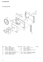
Description A-4440-289-A KEY BOARD, COMPLETE 4-910-502-01 CUSHION, ANTENNA 3-227-395-01 PANEL (SIDE) (EXCEPT EA) 3-227-395-11 PANEL (SIDE) (EA) 1-757-510-11 WIRE (FLAT TYPE) (18 CORE) Remarks Ref. Description Remarks 3-... 1-402-479-21 ANTENNA, FERRITE-ROD (LW/MW) LCD1 1-804-194-11 DISPLAY PANEL, LIQUID CRYSTAL SP201 1-529-942-11 SPEAKER (7.7cm) 18 No. 57 58 * 59 * 60 * 61 Part No. CHASSIS SECTION SP201 52 ANT102 56 55 57 54 51 61 LCD1 60 59 58 53 Ref. ICF-SW7600GR 5-2. No. * 51 52...
Description A-4440-289-A KEY BOARD, COMPLETE 4-910-502-01 CUSHION, ANTENNA 3-227-395-01 PANEL (SIDE) (EXCEPT EA) 3-227-395-11 PANEL (SIDE) (EA) 1-757-510-11 WIRE (FLAT TYPE) (18 CORE) Remarks Ref. Description Remarks 3-... 1-402-479-21 ANTENNA, FERRITE-ROD (LW/MW) LCD1 1-804-194-11 DISPLAY PANEL, LIQUID CRYSTAL SP201 1-529-942-11 SPEAKER (7.7cm) 18 No. 57 58 * 59 * 60 * 61 Part No. CHASSIS SECTION SP201 52 ANT102 56 55 57 54 51 61 LCD1 60 59 58 53 Ref. ICF-SW7600GR 5-2. No. * 51 52...
Service Manual
Page 24
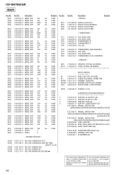
...510-11 WIRE (FLAT TYPE) (18 CORE) * 60 1-694-751-11 CONDUCTIVE BOARD, CONNECTION ANT101 1-501-712-11 ANTENNA, TELESCOPIC ANT102 1-402-479-21 ANTENNA, FERRITE-ROD (LW/MW) LCD1 1-804-194-11 DISPLAY PANEL, LIQUID CRYSTAL SP201 1-529-942-11 SPEAKER (7.7cm) ...,AEP,CH,E,JE,SP) 3-912-863-05 GUIDE, SHORT WAVE (EA) 8-953-130-90 HEADPHONE MDR-E805LP (JE) * A-3638-036-A ANTENNA, WIRE (SW) X-3329-657-1 ATTACHMENT(JE) RV101 RV201 RV202 RV203 RV204 1-227-317-11 RES, VAR, CARBON 20K (ATT) 1-227-...par une pièce portant le numéro spécifié. 24 ICF-SW7600GR MAIN Ref.
...510-11 WIRE (FLAT TYPE) (18 CORE) * 60 1-694-751-11 CONDUCTIVE BOARD, CONNECTION ANT101 1-501-712-11 ANTENNA, TELESCOPIC ANT102 1-402-479-21 ANTENNA, FERRITE-ROD (LW/MW) LCD1 1-804-194-11 DISPLAY PANEL, LIQUID CRYSTAL SP201 1-529-942-11 SPEAKER (7.7cm) ...,AEP,CH,E,JE,SP) 3-912-863-05 GUIDE, SHORT WAVE (EA) 8-953-130-90 HEADPHONE MDR-E805LP (JE) * A-3638-036-A ANTENNA, WIRE (SW) X-3329-657-1 ATTACHMENT(JE) RV101 RV201 RV202 RV203 RV204 1-227-317-11 RES, VAR, CARBON 20K (ATT) 1-227-...par une pièce portant le numéro spécifié. 24 ICF-SW7600GR MAIN Ref.


