Operating Instructions
Page 2
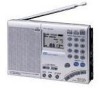
...built-in a particular installation. INFORMATION This equipment has been tested and found to Part 15 of a button. - This equipment generates, uses, and can enjoy FM broadcasts in this manual could void your Sony dealer regarding this equipment. Reorient or relocate the receiving antenna. - Manual tuning ... min. • Stereo FM reception You can radiate radio frequency energy and, if not installed and used in a residential installation. Owner's record The model and serial numbers are located at the time of the unit. ICF-SW7600GR Serial No Warning To prevent fire or shock hazard,...
...built-in a particular installation. INFORMATION This equipment has been tested and found to Part 15 of a button. - This equipment generates, uses, and can enjoy FM broadcasts in this manual could void your Sony dealer regarding this equipment. Reorient or relocate the receiving antenna. - Manual tuning ... min. • Stereo FM reception You can radiate radio frequency energy and, if not installed and used in a residential installation. Owner's record The model and serial numbers are located at the time of the unit. ICF-SW7600GR Serial No Warning To prevent fire or shock hazard,...
Operating Instructions
Page 3
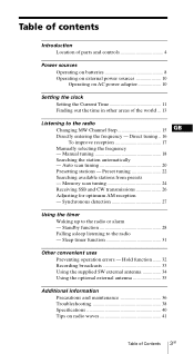
...Searching the station automatically - Auto scan tuning 20 Presetting stations - Synchronous detection 27 Using the timer Waking up to the radio - Hold function ....... 32 Recording broadcasts 33 Using the supplied SW external antenna 34 Using the optional external antenna 35 ...the frequency - Preset tuning 22 Searching available stations from presets - Standby function 28 Falling asleep listening to the radio or alarm - Table of contents Introduction Location of parts and controls 4 Power sources Operating on batteries 8 Operating on external power sources 10 Operating on...
...Searching the station automatically - Auto scan tuning 20 Presetting stations - Synchronous detection 27 Using the timer Waking up to the radio - Hold function ....... 32 Recording broadcasts 33 Using the supplied SW external antenna 34 Using the optional external antenna 35 ...the frequency - Preset tuning 22 Searching available stations from presets - Standby function 28 Falling asleep listening to the radio or alarm - Table of contents Introduction Location of parts and controls 4 Power sources Operating on batteries 8 Operating on external power sources 10 Operating on...
Operating Instructions
Page 4
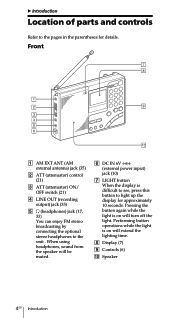
B Introduction Location of parts and controls Refer to the pages in the parentheses for approximately 10 seconds. When using headphones, sound from the speaker will be muted. 6 DC IN ...
B Introduction Location of parts and controls Refer to the pages in the parentheses for approximately 10 seconds. When using headphones, sound from the speaker will be muted. 6 DC IN ...
Operating Instructions
Page 5
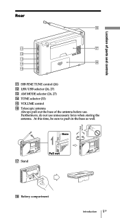
At this time, be sure to push in the base as well. Base qj Stand Pull out qk Battery compartment Introduction 5GB Rear Location of parts and controls qa SSB FINE TUNE control (26) qs LSB/USB selector (26, 27) qd AM MODE selector (26, 27) qf TONE selector (33) qg VOLUME control qh Telescopic antenna Always pull out the base of the antenna before use unnecessary force when storing the antenna. Furthermore, do not use .
At this time, be sure to push in the base as well. Base qj Stand Pull out qk Battery compartment Introduction 5GB Rear Location of parts and controls qa SSB FINE TUNE control (26) qs LSB/USB selector (26, 27) qd AM MODE selector (26, 27) qf TONE selector (33) qg VOLUME control qh Telescopic antenna Always pull out the base of the antenna before use unnecessary force when storing the antenna. Furthermore, do not use .
Operating Instructions
Page 7
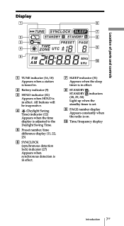
..., 29, 30) Light up when the standby timer is set. 9 PAGE number display Appears constantly when the radio is in . 2 Battery indicator (9) 3 HOLD indicator (32) Appears when HOLD is on. 0 Time/frequency display Introduction 7GB Display Location of parts and controls 1 TUNE indicator (16, 18) Appears when a station is tuned in effect.
..., 29, 30) Light up when the standby timer is set. 9 PAGE number display Appears constantly when the radio is in . 2 Battery indicator (9) 3 HOLD indicator (32) Appears when HOLD is on. 0 Time/frequency display Introduction 7GB Display Location of parts and controls 1 TUNE indicator (16, 18) Appears when a station is tuned in effect.
Operating Instructions
Page 40
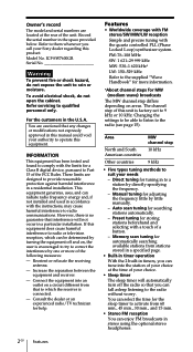
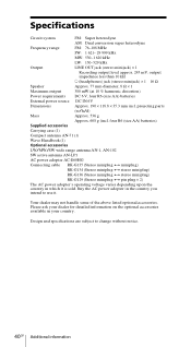
Please ask your country. projecting parts (w/h/d) Mass Approx. 536 g Approx. 608 g (incl. four R6 (size AA) batteries) Supplied accessories Carrying case (1) Compact antenna AN-71 (1) Wave Handbook (1) Optional accessories LW/MW/...
Please ask your country. projecting parts (w/h/d) Mass Approx. 536 g Approx. 608 g (incl. four R6 (size AA) batteries) Supplied accessories Carrying case (1) Compact antenna AN-71 (1) Wave Handbook (1) Optional accessories LW/MW/...
Service Manual
Page 1
projecting parts (w/h/d) Mass Approx. 536 g Approx. 608 g (incl. four R6 (size AA) batteries) Supplied accessories Carrying case (1) Compact antenna AN-71 (1) Wave Handbook (1) Design and specifications are subject to change without notice. 9-873-099-11 2001C1600-1 © 2001.3 Sony Corporation Audio Entertainment Group General Engineering Dept. ICF-SW7600GR SERVICE MANUAL Ver 1.0 2001. 03 US Model...
projecting parts (w/h/d) Mass Approx. 536 g Approx. 608 g (incl. four R6 (size AA) batteries) Supplied accessories Carrying case (1) Compact antenna AN-71 (1) Wave Handbook (1) Design and specifications are subject to change without notice. 9-873-099-11 2001C1600-1 © 2001.3 Sony Corporation Audio Entertainment Group General Engineering Dept. ICF-SW7600GR SERVICE MANUAL Ver 1.0 2001. 03 US Model...
Service Manual
Page 10
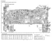
... model. No. No. No. ICF-SW7600GR 4-2. No. No. Location Ref. Location Ref. Location Ref. No. Caution: Pattern face side: (Conductor Side) Parts face side: (Component Side) Parts on the pattern face side seen from the parts face are indicated. Location Ref.... Q211 F-3 D109 E-9 D207 I T203 T203 A TO KEY BOARD 1 2 3 4 5 6 7 8 9 • Semiconductor Location Ref. Parts on Printed Wiring Boards: • X : parts extracted from the component side. • a : Through hole. • : Pattern from the side which enables seeing. (The other layers'...
... model. No. No. No. ICF-SW7600GR 4-2. No. No. Location Ref. Location Ref. Location Ref. No. Caution: Pattern face side: (Conductor Side) Parts face side: (Component Side) Parts on the pattern face side seen from the parts face are indicated. Location Ref.... Q211 F-3 D109 E-9 D207 I T203 T203 A TO KEY BOARD 1 2 3 4 5 6 7 8 9 • Semiconductor Location Ref. Parts on Printed Wiring Boards: • X : parts extracted from the component side. • a : Through hole. • : Pattern from the side which enables seeing. (The other layers'...
Service Manual
Page 11
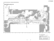
... pattern face side seen from the parts face are indicated. 4-3. PRINTED WIRING BOARD - MAIN BOARD (COMPONENT SIDE) - A MAIN BOARD (COMPONENT SIDE) B ICF-SW7600GR C D E F US G B H TO KEY BOARD I 11 1-679-368- (11) 15 16 17 18 19 20 21 22 23 24 25 ...26 27 28 11 11 Note on Printed Wiring Boards: • X : parts extracted from the component side. • a : Through hole. •...
... pattern face side seen from the parts face are indicated. 4-3. PRINTED WIRING BOARD - MAIN BOARD (COMPONENT SIDE) - A MAIN BOARD (COMPONENT SIDE) B ICF-SW7600GR C D E F US G B H TO KEY BOARD I 11 1-679-368- (11) 15 16 17 18 19 20 21 22 23 24 25 ...26 27 28 11 11 Note on Printed Wiring Boards: • X : parts extracted from the component side. • a : Through hole. •...
Service Manual
Page 14
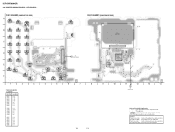
... enables seeing. (The other layers' patterns are not indicated.) Caution: Pattern face side: (Conductor Side) Parts face side: (Component Side) Parts on the parts face side seen from the pattern face are indicated. 14 No. ICF-SW7600GR 4-6. S303 3 B S302 2 ON OFF S301 1 S307 6 S306 5 S305 4 C S311 S310 ...IC303 21 34 S328 ENTER 2 1 IC304 34 A TO MAIN BOARD 11 1-679-367- (11) 1 2 3 4 5 6 7 • Semiconductor Location Ref. Parts on the pattern face side seen from the parts face are indicated. KEY BOARD (CONDUCTOR SIDE) A S304 POWER S308 SLEEP S329 HOLD.
... enables seeing. (The other layers' patterns are not indicated.) Caution: Pattern face side: (Conductor Side) Parts face side: (Component Side) Parts on the parts face side seen from the pattern face are indicated. 14 No. ICF-SW7600GR 4-6. S303 3 B S302 2 ON OFF S301 1 S307 6 S306 5 S305 4 C S311 S310 ...IC303 21 34 S328 ENTER 2 1 IC304 34 A TO MAIN BOARD 11 1-679-367- (11) 1 2 3 4 5 6 7 • Semiconductor Location Ref. Parts on the pattern face side seen from the parts face are indicated. KEY BOARD (CONDUCTOR SIDE) A S304 POWER S308 SLEEP S329 HOLD.
Service Manual
Page 17
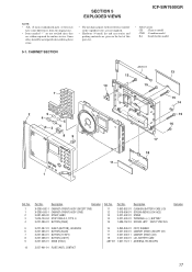
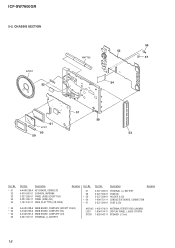
...) 3-881-938-00 STRAP, HAND 7-624-104-04 STOP RING 2.0, TYPE -E 3-227-386-01 BUTTON (PAGE) Ref. SECTION 5 EXPLODED VIEWS ICF-SW7600GR NOTE: • -XX, -X mean standardized parts, so they may have some differences from the original one. • Items marked "*" are not stocked since they are given in the exploded...are not supplied. • Hardware (# mark) list and accessories and packing materials are seldom required for routine service. No. 11 12 13 14 15 Part No. Description 3-893-852-01 3-918-696-01 3-227-402-01 3-227-403-01 7-685-152-19 CUSHION (BATTERY CASE LID) SCREW (M3X6...
...) 3-881-938-00 STRAP, HAND 7-624-104-04 STOP RING 2.0, TYPE -E 3-227-386-01 BUTTON (PAGE) Ref. SECTION 5 EXPLODED VIEWS ICF-SW7600GR NOTE: • -XX, -X mean standardized parts, so they may have some differences from the original one. • Items marked "*" are not stocked since they are given in the exploded...are not supplied. • Hardware (# mark) list and accessories and packing materials are seldom required for routine service. No. 11 12 13 14 15 Part No. Description 3-893-852-01 3-918-696-01 3-227-402-01 3-227-403-01 7-685-152-19 CUSHION (BATTERY CASE LID) SCREW (M3X6...
Service Manual
Page 18
...) 18 No. 57 58 * 59 * 60 * 61 Part No. Description A-4440-289-A KEY BOARD, COMPLETE 4-910-502-01 CUSHION, ANTENNA 3-227-395-01 PANEL (SIDE) (EXCEPT EA) 3-227-395-11 PANEL (SIDE) (EA) 1-757-510-11 WIRE (FLAT TYPE) (18 CORE) Remarks Ref. ICF-SW7600GR 5-2. No. * 51 52 53 53 54 * 55 * 55...
...) 18 No. 57 58 * 59 * 60 * 61 Part No. Description A-4440-289-A KEY BOARD, COMPLETE 4-910-502-01 CUSHION, ANTENNA 3-227-395-01 PANEL (SIDE) (EXCEPT EA) 3-227-395-11 PANEL (SIDE) (EA) 1-757-510-11 WIRE (FLAT TYPE) (18 CORE) Remarks Ref. ICF-SW7600GR 5-2. No. * 51 52 53 53 54 * 55 * 55...
Service Manual
Page 19
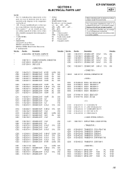
.... Replace only with mark 0 are critical for safety. SECTION 6 ELECTRICAL PARTS LIST ICF-SW7600GR KEY NOTE: • Due to standardization, replacements in the parts list may be anticipated when ordering these items. • CAPACITORS: uF: µF • RESISTORS All resistors are in the diagrams or the components used on ...
.... Replace only with mark 0 are critical for safety. SECTION 6 ELECTRICAL PARTS LIST ICF-SW7600GR KEY NOTE: • Due to standardization, replacements in the parts list may be anticipated when ordering these items. • CAPACITORS: uF: µF • RESISTORS All resistors are in the diagrams or the components used on ...

Service Manual
Page 20
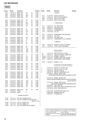
No. R305 Part No. ICF-SW7600GR KEY Ref. Part No. Description Remarks 5% 1/16W R362 1-216-821-11 METAL CHIP 1K 5% 1/16W R363 1-216-821-11 METAL CHIP 1K 5% 1/16W 5% 1/16W R364 1-216-857-11 ...
No. R305 Part No. ICF-SW7600GR KEY Ref. Part No. Description Remarks 5% 1/16W R362 1-216-821-11 METAL CHIP 1K 5% 1/16W R363 1-216-821-11 METAL CHIP 1K 5% 1/16W 5% 1/16W R364 1-216-857-11 ...

Service Manual
Page 22
...-64 TRANSISTOR 2SK508-K51 22 C256 C257 C258 C259 C260 C261 C262 C263 C264 C265 C266 C267 C268 C269 C270 C271 C272 C273 C274 C277 Part No. ICF-SW7600GR MAIN Ref. D107 D108 D109 D110 D111 D201 D202 D203 D204 D205 D206 D207 IC201 IC202 IC203 IC204...
...-64 TRANSISTOR 2SK508-K51 22 C256 C257 C258 C259 C260 C261 C262 C263 C264 C265 C266 C267 C268 C269 C270 C271 C272 C273 C274 C277 Part No. ICF-SW7600GR MAIN Ref. D107 D108 D109 D110 D111 D201 D202 D203 D204 D205 D206 D207 IC201 IC202 IC203 IC204...
Service Manual
Page 24
Part No. Part No. Description Remarks R227 1-216-841-11 METAL CHIP 47K 5% R228 1-216-809-11 METAL CHIP 100 5% R229 1-216-855-11 METAL CHIP 680K 5% R230 1-... with part number specified. Les composants identifiés par une marque 0 sont critiques pour la sécurité. Ne les remplacer que par une pièce portant le numéro spécifié. 24 No. Description Remarks Ref. Replace only with mark 0 are critical for safety. No. ICF-SW7600GR MAIN...
Part No. Part No. Description Remarks R227 1-216-841-11 METAL CHIP 47K 5% R228 1-216-809-11 METAL CHIP 100 5% R229 1-216-855-11 METAL CHIP 680K 5% R230 1-... with part number specified. Les composants identifiés par une marque 0 sont critiques pour la sécurité. Ne les remplacer que par une pièce portant le numéro spécifié. 24 No. Description Remarks Ref. Replace only with mark 0 are critical for safety. No. ICF-SW7600GR MAIN...


